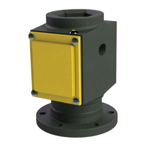
Noark ASD25DC User manual

Air Circuit Breaker
Usage Manual
ZASD25DC202208UL
NOARK ASD25DC
PV/BPS Air switch disconnectors from 800A to 2500A are certified to
UL 489/UL 489B
User Manual

Installation manual
Overview 01
Product parameters 02
Environmental conditions 02
Connection type 03
Package identification 05
Storage 06
Necessary tools 07
Handling 08
Unpacking 09
Installation Dimension 10
Accessories 26
Control circuit wiring 30
Contents

User Manual 01
1
7
8
9
10
11
2
3
4
5
6
Overview
1. Control circuit wiring terminal
6. Fixed plate (left)
2. Brand
3. Opening push-button (O)
4. Contact position indicator
5. Closing ready indicator
7. Closing push-button (I)
10. Spring charged/discharged indicator
C
h
a
r
g
e
d
Discharged
a) Spring charged
b) Spring discharged
a) ready
b) not ready
a) opening
b) closing
OFF
ON
OK
OK
8. Manual spring charge handle
9. Nameplate
11. Fixed plate (right)
Overview
This device should be installed, operated, serviced and maintained only by professional personnel.
Noark Electric is not responsible for any consequences caused by non-compliance with this the manual.
After unpacking the product, check for any damage and the integrity of other items.
Do not install the product in inflammable, explosive, humid and condensing environment.
Do not install the product at places where gas medium can cause metal corrosion and insulation damage.
Connect the product to the proper power supply and standard wires.
Leave sufficient space and safe distance around the product.
Do not touch the conductive parts during operation.
Disconnect all the power sources during installation and maintenance.
Failure to follow the above instructions may result in equipment damage, personal injury or even death.
Environmental protection
To protect environment, this product and its components should be disposed properly as industrial waste upon
end of life; or delivered to recycling plant who will dismantle and recycle the product according to relevant
national regulations.
UL489
UL file number:E529657
UL489B
UL file number:E529658
Codes and Standards

User Manual 03User Manual 02
Product parameters Connection type
Type ASD25DC
Pole 4P
Installation Fixed
Rated current(A) 800A/1000A/1250A/1600A/2000A/2500A
Rated Maximum Volatge(V) DC1500
Short circuit withstand current (kA) 120/150
Operating time(ms) Max.openning time Max.openning time ≤30
Max.closing time Max.closing time ≤70
Life cycle(time) Mechanical 12500
Electrical 2000
External dimensions
Inches(mm) H×W×D
800A-2000A 15.43×18.31×17.01 (392×465×433)
2500A 15.43×18.31×18.78 (392×465×477)
Enclosure dimensions
Inches(mm) H×W×D
21.73×23.62×13.86 (552×600×352)
Ventilation Area Top: 18183mm²
TypeC
Upper Supply Lower supply
TypeD
Environmental conditions
Ambient temperature
Altitude
Humidity
Rated
Current(A)
Temperature(℃)
Horizontial type Vertical type
<40 45 50 55 60 65 70 <40 45 50 55 60 65 70
800 100% 100% 100% 100% 100% 100% 100% 100% 100% 100% 100% 100% 100% 100%
1600 100% 100% 100% 100% 100% 95% 90% 100% 100% 100% 100% 100% 100% 100%
2000 100% 100% 100% 100% 95% 90% 85% 100% 100% 100% 100% 100% 95% 93%
2500 100% 100% 100% 95% 90% 85% 80% 100% 100% 100% 100% 95% 93% 90%
Altitude(m)
<2000 3000 4000 5000
Rated Voltage(V) 1xIn 0.9xIn 0.8xIn 0.7xIn
Rated Current(A) 1xIn 0.98xIn 0.96xIn 0.94In
ASD25DC air switch disconnector can operate in -40℃~ 70℃environmental conditions.
ASD25DC air switch disconnector can operate at higher temperatures than the reference temperature 40℃,in this case,the derating
coefficients shown in the table must be applied.
ASD25DC air switch disconnector do not undergo changes in rated performance up to 2000m.Beyond this altitude ,the derating
coefficients shown in the table must be applied.
The relative humidity does not exceed 85% at 40℃,the monthly average maximum of relative humidity in the wettest month
does not exceed 90%.
The effect of surface condensation caused by temperature changes on product performance should be taken into consideration.
*Configuration C for ungrounded system only
*Configuration D for either grounded or ungrounded in PV system
Load
+(-) -(+)
Load
+(-)
-(+)
Load
+(-) -(+)
Load
+(-)
-(+)

User Manual 05User Manual 04
1PCS
1
1
ASD25DC
Conform standard:
UL 489/UL 489B
1 2 3 4 5 6 7 8 9 1 2 3 4 5 6 7 9 81 2 3 4 5 6 7 8 9 1 2 3 4 5 6 7 9 8
NOARK Electrics (USA),Inc.
PV/BPS Molded Case Switch
1800404
ASD25DCH4FVC2500
1800278 +UVT12NC AC/DC110~130V
1800270 +SHT12NC AC/DC110~130V
1800262 +XF12NC AC/DC110~130V
1800429 +MD11NA DC24~30V
1800287
+AX12NF66
File E529657
File E529658
ASD25DC
Conform standard:
UL 489/UL 489B
1234 5 6789 1 234567 9 81 234 5 6789 1 234567 9 8
NOARK Electrics (USA),Inc.
PV/BPS Molded Case Switch
1800404 ASD25DCH4FVC2500
1800278 +UVT12NC AC/DC110~130V
1800270 +SHT12NC AC/DC110~130V
1800262 +XF12NC AC/DC110~130V
1800429 +MD11NA DC24~30V
1800287 +AX12NF66
File E529657
File E529658
Connection type
Jumper busbars dimensions
Applicable busbar as following:
800-2000A:
2500A:
Rated Current Horizontal type Vertical type
800A
6.35TX76.2X1ea (inch:1/4X3X1ea) 6.35TX76.2X1ea (inch:1/4X3X1ea)
10TX50X1ea 10TX50X1ea
1000A
6.35TX50.8X2ea (inch:1/4X2X2ea) 6.35TX50.8X2ea (inch:1/4X2X2ea)
6TX50X2ea 6TX50X2ea
1200A
6.35TX57.2X2ea (inch:1/4X2 1/4X2ea) 6.35TX57.2X2ea(inch:1/4X2 1/4X2ea)
8TX50X2ea 8TX50X2ea
1600A
6.35TX76.2X2ea (inch:1/4X3X2ea) 6.35TX76.2X2ea (inch:1/4X3X2ea)
10TX50X2ea 10TX50X2ea
2000A
6.35TX101.6X2ea (inch:1/4X4X2ea) 6.35TX101.6X2ea (inch:1/4X4X2ea)
10TX80X2ea 10TX80X2ea
2500A
6.35TX127X2ea (inch:1/4X5X2ea)
10TX80X2ea 10TX80X2ea
10TX100X2ea 10TX100X2ea
Package identification
6.89(175)
8×∅0.51(∅13)
8×∅0.51(∅13)
8×∅0.51(∅13)
2.17(55)
1.57(40) 1.57(40)
1.57(40)
1.57(40)
3.15(80)
3.15(80)
1.57(40)1.57(40) 0.59(15)0.59(15)
0.39(10)
0.39(10)
0.39(10)
4.53(115)
2.95(75)
0.79(20)
0.79(20)
1.57(40)
3.94(100)
5.12(130)
1.1(28)
4.72(120)

User Manual 07User Manual 06
1PCS
1
1
ASD25DC
Conform standard:
UL 489/UL 489B
1 2 3 4 5 6 7 8 9 1 2 3 4 5 6 7 9 81 2 3 4 5 6 7 8 9 1 2 3 4 5 6 7 9 8
NOARK Electrics (USA),Inc.
PV/BPS Molded Case Switch
1800404
ASD25DCH4FVC2500
1800278 +UVT12NC AC/DC110~130V
1800270 +SHT12NC AC/DC110~130V
1800262 +XF12NC AC/DC110~130V
1800429 +MD11NA DC24~30V
1800287
+AX12NF66
File E529657
File E529658
ASD25DC
Conform standard:
UL 489/UL 489B
1234 5 6789 1 234567 9 81 234 5 6789 1 234567 9 8
NOARK Electrics (USA),Inc.
PV/BPS Molded Case Switch
1800404
ASD25DCH4FVC2500
1800278 +UVT12NC AC/DC110~130V
1800270 +SHT12NC AC/DC110~130V
1800262 +XF12NC AC/DC110~130V
1800429 +MD11NA DC24~30V
1800287
+AX12NF66
File E529657
File E529658
installation bolt:Hex Cap Screws:7/16 in x 23
4in
Hex Cap Screws :
17
0.67(17)
7/16 in x 2 3
4in
in/mm
Storage Necessary tools
Application in Control Circuit Wiring
Installation Bolt

User Manual 09User Manual 08
Handling
Handling
800A/2000A 2500A
Type C
net weight 154/70 net weight 160/73
gross weight 198/90 gross weight 205/93
Type D
net weight 163/74 net weight 168/76
gross weight 207/94 gross weight 211/96
unit : lb/kg
Unpacking
Nameplate example
:
:

User Manual 11User Manual 10
800A/1000A/1250A/1600A/2000A
Horizontal installation
Type C
in(mm) in(mm)
800A/1000A/1250A/1600A/2000A
Horizontal installation
Type C
Upper supply Lower supply
Installation Dimension Installation Dimension
Y
X
Y
X
3.58(91)
3.58(91)
3.17(80.5)
3.17(80.5)
11.02(280)
11.02(280)
10.51(267)
10.51(267)
7.28(185)
X
Y
Y
7.28(185)
6.77(172)
6.77(172)
5.75(146)
5.75(146)
5.75(146)
5.75(146)
FF
FF
8.64(219.5)
8.64(219.5)
13.46(342)
13.46(342)
8×∅0.24(∅6) 8×∅0.24(∅6)
16×∅0.51(∅13)
16×∅0.51(∅13)
Max overlap : 3.27(83)
Panel perforating size
Max overlap : 3.27(83)
13.97(355) 13.97(355)
9.84(250) 9.84(250)
12(305) 12(305)
13.46(342) 13.46(342)
12.28(312) 12.28(312)
0.79(20)
7.2(183)
5.08(129)
5.08(129)
5.08(129)
5.08(129)
9(228.5)6.44(163.5)
6.44(163.5) 9(228.5)
0.47(12)
0.47(12)
5.91(150)
5.91(150)
1.57(40)
1.57(40)
1.57(40)
1.57(40)
1.57(40)
1.57(40)
1.57(40)
7.2(183)
1.97(50)
0.79(20)
3.15(80)
3.15(80)
3.74(95)
3.74(95)
3.74(95)
3.74(95)
3.74(95)
3.74(95)
1.57(40)
1.57(173)
12.24(311)
12.24(311)
10.55(268)
10.55(268)
Panel perforating size
X
Y
Y

User Manual 13User Manual 12
800A/1000A/1250A/1600A/2000A
Vertical installation
Type C
in(mm) in(mm)
800A/1000A/1250A/1600A/2000A
Vertical installation
Type C
Upper supply Lower supply
Installation Dimension Installation Dimension
Y
X
Y
X
3.58(91) 3.58(91)
3.17(80.5) 3.17(80.5)
11.02(280) 11.02(280)
7.28(185)
XX
Y
Y
Y
Y
7.28(185)
5.75(146) 5.75(146)
5.75(146) 5.75(146)
FF
8.64(219.5) 8.64(219.5)
13.46(342) 13.46(342)
5.08(129)
5.08(129)
5.08(129)
5.08(129)
9(228.5)
9(228.5)
6.44(163.5)
6.44(163.5)
1.57(40)
1.57(40)
1.57(40)
1.57(40)
10.51(267) 10.51(267)
6.77(172) 6.77(172)
8×∅0.24(∅6) 8×∅0.24(∅6)
13.97(355) 13.97(355)
12.28(312) 12.28(312)
0.47(12)
0.47(12)
5.91(150)
5.91(150)
12.24(311)
12.24(311)
10.55(268)
10.55(268)
F
F
Max overlap : 3.27(83)
Max overlap : 3.27(83)
9.84(250)
9.84(250)
12(305)
12(305)
13.46(342)
1.57(40)
1.57(40)
1.57(40)
0.79(20) 0.79(20)
0.79(20)
6.81(173)
6.02(153)
0.79(20)
3.15(80)
3.15(80)
3.74(95) 3.74(95)
3.74(95) 3.74(95)
3.74(95) 3.74(95)
16×∅0.51(∅13)
Panel perforating size Panel perforating size

User Manual 15User Manual 14
2500A
Horizontal installation
Type C
2500A
Horizontal installation
Type C
in(mm)
Upper supply
Installation Dimension Installation Dimension
in(mm)
Lower supply
Y
X
Y
X
3.58(91) 3.58(91)
3.17(80.5) 3.17(80.5)
11.02(280) 11.02(280)
10.51(267)
10.51(267)
6.77(172)
6.77(172)
0.39(10)
5.75(146) 5.75(146)
5.75(146) 5.75(146)
FF
F
FF
8.64(219.5) 8.64(219.5)
15.2(386)
15.2(386)
14.37(365) 14.37(365)
8×∅0.24(∅6)
8×∅0.24(∅6)
16×∅0.51(∅13)
16×∅0.51(∅13)
Max overlap : 3.27(83)
Max overlap : 3.27(83)
13.97(355)
13.97(355)
12.83(326) 12.83(326)
12.28(312)
12.28(312)
0.79(20)
0.79(153)
0.79(20)
5.08(129)
5.08(129)
5.08(129)
5.08(129)
9(228.5)
9(228.5)
6.44(163.5)
6.44(163.5)
0.47(12)
0.47(12)
5.91(150)
5.91(150)
1.57(40)
1.57(40)
1.57(40)
1.57(40)
7.3(185.5)
0.79(20)
3.15(80)
3.15(80)
3.15(80)
3.15(80)
0.59(15)
0.59(15)2.07(52.5)
4.53(115)
4.53(115)
4.53(115)
4.53(115)
4.53(115)
4.53(115)
12.24(311)
12.24(311)
10.55(268)
10.55(268)
7.28(185)
XX
YY
Y
Y
7.28(185)
Panel perforating size Panel perforating size

User Manual 17User Manual 16
2500A
Vertical installation
Type C
2500A
Vertical installation
Type C
in(mm)
Upper supply
Installation Dimension Installation Dimension
in(mm)
Lower supply
Y
X
Y
X
3.58(91) 3.58(91)
3.17(80.5) 3.17(80.5)
11.02(280) 11.02(280)
10.51(267) 10.51(267)
6.77(172) 6.77(172)
5.75(146) 5.75(146)
5.75(146) 5.75(146)
FF
FF
8.64(219.5) 8.64(219.5)
8×∅0.24(∅6)
8×∅0.24(∅6)
16×∅0.51(∅13)
16×∅0.51(∅13)
Max overlap : 3.27(83)
Max overlap : 3.27(83)
13.97(355) 13.97(355)
12.28(312) 12.28(312)
0.79(20) 0.79(20)
5.08(129)
5.08(129)
5.08(129)
5.08(129)
9(228.5)
9(228.5)
6.44(163.5)
6.44(163.5)
0.47(12)
0.47(12)
5.91(150)
5.91(150)
1.57(40)
1.57(40)
1.57(40)
1.57(40)
6.02(153)
0.79(20)
0.79(20)
0.79(20)
0.79(153)
3.15(80)
3.15(80)
3.15(80)
12.24(311)
12.24(311)
10.55(268)
10.55(268)
7.28(185)
XX
YY
Y
Y
7.28(185)
9.84(250)
9.84(250)
12(305)
12(305)
14.37(365)
14.37(365)
3.74(95) 3.74(95)
3.74(95) 3.74(95)
3.74(95) 3.74(95)
Panel perforating size Panel perforating size

User Manual 19User Manual 18
800A/1000A/1250A/1600A/2000A
Horizontal installation
Type D
800A/1000A/1250A/1600A/2000A
Horizontal installation
Type D
in(mm)
Upper supply
Installation Dimension Installation Dimension
in(mm)
Lower supply
Y
X
Y
X
3.58(91) 3.58(91)
3.17(80.5) 3.17(80.5)
11.02(280)
11.02(280)
10.51(267)
10.51(267)
6.77(172)
6.77(172)
5.75(146) 5.75(146)
5.75(146) 5.75(146)
FF
F
F
8.64(219.5)
8.64(219.5)
8×∅0.24(∅6)
8×∅0.24(∅6)
8×∅0.51(∅13) 8×∅0.51(∅13)
Max overlap : 3.27(83)
Max overlap : 3.27(83)
13.97(355)
13.97(355)
12.28(312)
12.28(312)
5.08(129)
5.08(129)
5.08(129)
5.08(129)
9(228.5)
9(228.5)
6.44(163.5)
6.44(163.5)
0.47(12)
0.47(12)
5.91(150)
5.91(150)
1.57(40)
1.57(40)
1.57(40)
1.97(50)
1.57(40)
1.57(40)
1.57(173)
1.57(40) 1.57(40)
7.2(183)
0.79(20)
3.15(80) 3.15(80)
12.24(311)
12.24(311)
10.55(268)
10.55(268)
7.28(185)
X
X
Y
Y
Y
Y
7.28(185)
9.84(250)
9.84(250)
12(305)
12(305)
13.46(342)
13.46(342)
13.46(342)
13.46(342)
7.48(190) 7.48(190)
3.74(95) 3.74(95)
Panel perforating size
Panel perforating size

User Manual 21User Manual 20
800A/1000A/1250A/1600A/2000A
Vertical installation
Type D
800A/1000A/1250A/1600A/2000A
Vertical installation
Type D
in(mm)
Upper supply
Installation Dimension Installation Dimension
in(mm)
Lower supply
Y
X
Y
X
3.58(91)
3.58(91)
3.17(80.5)
3.17(80.5)
11.02(280)
11.02(280)
10.51(267)
10.51(267) 6.77(172)
6.77(172)
5.75(146)
5.75(146) 5.75(146)
5.75(146)
F
F
F
F
8.64(219.5)
8.64(219.5)
8×∅0.24(∅6)
8×∅0.24(∅6)
8×∅0.51(∅13)
8×∅0.51(∅13) Max overlap : 3.27(83)
Max overlap : 3.27(83)
13.97(355)
13.97(355)
12.28(312)
12.28(312)
5.08(129)
5.08(129)
5.08(129)
5.08(129)
9(228.5)
9(228.5)
6.44(163.5)
6.44(163.5)
0.47(12)
0.47(12)
5.91(150)
5.91(150)
1.57(40)
1.57(40)
1.57(40)
1.57(40)
1.57(40)
1.57(40)
1.57(40)
1.57(40)
0.79(20)
0.79(20)
0.79(20)
3.15(80)
3.15(80)
6.81(173)
6.02(153)
12.24(311)
12.24(311)
10.55(268)
10.55(268)
7.28(185)
7.28(185)
XX
YY
Y
Y
9.84(250)
9.84(250)
12(305)
12(305)
13.46(342)
13.46(342)
13.46(342)
7.48(190)
7.48(190) 3.74(95)
3.74(95)
Panel perforating size Panel perforating size

User Manual 23User Manual 22
2500A
Horizontal installation
Type D
2500A
Horizontal installation
Type D
in(mm)
Upper supply
Installation Dimension Installation Dimension
in(mm)
Lower supply
Y
X
Y
X
3.58(91) 3.58(91)
3.17(80.5) 3.17(80.5)
11.02(280)
11.02(280)
10.51(267)
10.51(267)
6.77(172)
6.77(172)
5.75(146) 5.75(146)
5.75(146) 5.75(146)
FF
F
F
8.64(219.5) 8.64(219.5)
8×∅0.24(∅6) 8×∅0.24(∅6)
8×∅0.51(∅13)
8×∅0.51(∅13)
13.97(355)
13.97(355)
12.28(312)
12.28(312)
5.08(129)
5.08(129)
5.08(129)
5.08(129)
9(228.5)
9(228.5)
6.44(163.5)
6.44(163.5)
0.47(12)
0.47(12)
5.91(150)
5.91(150)
1.57(40)
1.57(40)
1.57(40)
1.57(40)
7.3(185.5)
2.07(52.5)
0.79(20)
0.79(20)
0.79(153)
0.59(15)
0.59(15)
3.15(80)
3.15(80)
3.15(80)
8.66(220)
8.66(220)
4.92(125)
4.92(125)
12.24(311)
12.24(311)
10.55(268)
10.55(268)
7.28(185)
XX
Y
Y
Y
Y
7.28(185)
15.2(386)
15.2(386)
12.83(326)
12.83(326)
14.37(365) 14.37(365)
Max overlap : 3.27(83)
Panel perforating size
Panel perforating size

User Manual 25User Manual 24
2500A
Vertical installation
Type D
2500A
Vertical installation
Dype D
in(mm)
Upper supply
Installation Dimension Installation Dimension
in(mm)
Lower supply
Y
X
Y
X
3.58(91) 3.58(91)
3.17(80.5) 3.17(80.5)
11.02(280) 11.02(280)
10.51(267) 10.51(267)
6.77(172) 6.77(172)
5.75(146) 5.75(146)
5.75(146) 5.75(146)
FF
FF
8.64(219.5) 8.64(219.5)
8×∅0.24(∅6)
8×∅0.24(∅6)
8×∅0.51(∅13)
8×∅0.51(∅13)
Max overlap : 3.27(83)
Max overlap : 3.27(83)
13.97(355)
13.97(355)
12.28(312)
12.28(312)
5.08(129)
5.08(129)
5.08(129)
5.08(129)
9(228.5)
9(228.5)
6.44(163.5)
6.44(163.5)
1.53(40)
1.57(40)
1.57(40)
1.57(40)
0.79(20)
0.79(20)
0.79(20)
0.79(20)
0.79(153)
3.15(80)
3.15(80)
3.15(80)
3.15(80)
6.02(153)
12.24(311)
12.24(311)
10.55(268)
10.55(268)
7.28(185)
XX
YY
Y
Y
7.28(185)
9.84(250)
9.84(250)
12(305)
12(305)
14.37(365) 14.37(365)
7.48(190)
7.48(190)
3.74(95)
3.74(95)
0.47(12)
0.47(12)
5.91(150)
5.91(150)
Panel perforating size
Panel perforating size

User Manual 27User Manual 26
Undervoltage release/UVT
Shunt trip release/SHT
Closing release/XF
Auxiliary contact/AX
Motor operator
The auxiliary contact remotely monitors ON/OFF position of air switch disconnector from
remote place.
Contact configuration:
44: 4NO and 4NC;66: 6NO and 6NC;
44C: 4NO or 4NC;66C: 6NO or 6NC.
The electric motor charges the closing spring of mechanism when the air switch
disconnector is closed.
Factory installed only.
Mechanical charging handle can be used when maintaining or without power supply.
Equipped with a limit switch contact which signals that spring is charged.
Voltage /V Rated Current /
A
AC 240 5
480 2
DC 110 0.25
220 0.25
Mechanical interlocks with cables
For mutual interlocking of 2 or 3 (in preparation) switches
Mechanical interlock with cable
Cable length for maximum distance of mounting positions of interlocks 78in(2m)
Suitable for ASD25DC air switch disconnector.
Scope of delivery: 2 interlocks and 2 cables (2 switches version), 3 interlocks and 6 cables (3 switches version)
78in/2m(max)
AB
AB
0
1
0
0
01
Circuit diagram On/Off state
User Manual 26
Safety shutter
Safety shutter lock
Mechanical interlocks with cables
It is the automatic safety device to protect the connectors of main circuits by cutting off dangerous
contact from outside while the breaker is draw out. When the main breaker is drawn in, the safety
shutter is automatically open.
Only available for withdrawable circuit breaker & non-automatic switch.
rp ot rettuhs ytefas eht kcol ,noitisop detcennocsid ta si rekaerb niam eht nehW event main
breaker pushed in.
Only available for withdrawable circuit breaker & non-automatic switch.
Lock is not provided.
Diameter of the lock should be 0.12in to 0.22in.
For mutual interlocking of 2 or 3 (in preparation) breakers
Mechanical interlock with cable
Cable length for maximum distance of mounting positions of interlocks 78in(2m)
Suitable for A32 Power circuit breaker and ASD32 No-automatic switch
Scope of delivery: 2 interlocks and 2 cables (2 breakers version), 3 interlocks and 6 cables (3 breakers version)
Accessories
78in/2m(max)
AB
AB
0
1
0
0
01
Circuit diagram On/Off state
Accessories Accessories
The undervoltage release is an optional device on both manually and electrically operated
air switch disconnectors. It opens the switch when its supply voltage falls to 30–60%
of rated voltage. If the release is not energized to 85% of its supply voltage, the switch
disconnector can not be closed electrically or manually.
Undervoltage release ratings:
Control voltages
Operational
voltage range
85%-110%
Dropout voltage
30%-60%
Inrush/continuous
power consumption Operating time(ms)
24-30Vdc 20-23Vdc 7-14Vdc 450W/4.5W 70
48-60Vac/dc 41-66Vac/dc 14-29Vac/dc 275W/4.5W 70
110-130Vac/dc 94-143Vac/dc 33-78Vac/dc 275W/4.5W 70
200-240Vac/dc 170-264Vac/dc 60-144Vac/dc 275W/4.5W 70
380-415Vac 323-457Vac 114-249Vac 275W/4.5W 70
The shunt trip is an optional device on air switch disconnectors.It opens the switch
disconnector instantaneously when its coil is energized by a voltage input.
Shunt trip ratings:
Control voltages
Operational
voltage range
70%-110%
Inrush/continuous
power consumption Operating time(ms)
24-30Vdc 17-33Vdc 450W/4.5W 35
48-60Vac/dc 34-66Vac/dc 275W/4.5W 35
110-130Vac/dc 77-143Vac/dc 275W/4.5W 35
200-240Vac/dc 146-264Vac/dc 275W/4.5W 35
380-415Vac 266-458.5Vac 275W/4.5W 35
The closing release is an optional device. It remotely closes the air switch disconnector
when the coil is energized by a voltage input.
Shunt release ratings:
Control voltages
Operational
voltage range
70%-110%
Inrush/continuous
power consumption Operating time(ms)
24-30Vdc 17-33Vdc 450W/4.5W 35
48-60Vac/dc 34-66Vac/dc 275W/4.5W 35
110-130Vac/dc 77-143Vac/dc 275W/4.5W 35
200-240Vac/dc 146-264Vac/dc 275W/4.5W 35
380-415Vac 266-458.5Vac 275W/4.5W 35

User Manual 29User Manual 28
OFF position keylock/KLK
Pushbutton lock device/VBP
Doorframes
Suitable for ASD25DC air switch disconnector
Block a switch in OFF position to ensure the switch can not be closed
One switch is provided with one lock and one key
Two switches are provided with two locks and one key
Three switches are provided with three locks and two keys
The cover prevents the access to control push button of the switch
Factory installed only
Scope of delivery: Lockable cover (lock with key is not a part of delivery)
In the scope of delivery for each switch
Degree of protection IP40
Phase barriers
Improve insulation level between main terminals
Delivered as set ( 3 pcs for 4P version)
Accessories Accessories

User Manual 31User Manual 30
ASD25DC air switch disconnector control circuit reference wiring diagram
Control circuit wiring
main circuit Auxiliary contact for user
Control powerReference wiring diagram as following
Energy
storage
indication
Undervoltage
Opening Closing
Ready to
close
indication
C04 4 groups C06 6 groups N4 4NO,4NC N6 6NO,6NC
Ready to close contact indication (optional)
9#,10#,11#: ready to close contact indication;
Signal indicator should be provided by user itself.
MD spring charge motor working power
30#, 31#, 32#: MD spring charge motor working power input;
Spring chargr indicator should be provided by user itself.
UVT undervoltage relasse (optional)
33#, 34#: UVT undervoltage release working power input;
SB3 emergency disconnecting button should be provided by user
itself.
Undervoltage release is within special order range, wiring are not
provided for regular supply.
SHT shunt release
35#, 36#: SHT shunt release working power input, if DC working
voltage is used, 35# is positive pole, 36# is negative pole. SB1
opening button should be provided by user itself.
XF shunt release
37#, 38#: XF closing coil working power input, if DC working voltage
is used, 37# is positive pole, 38# is negative pole. SB2 closing button
should be provided by user itself.
AX1 - AX6 auxiliary contacts
39# - 62# (AX1 - AX6): C04 for regular suuply, C06、N4、N6 for
specially ordered.
http://na.noark-electric.com
ZASD25DC202208UL
Table of contents
Other Noark Switch manuals

