Noblift EFS Series User manual

Operating Instructions
Parts List
EFS Series
Hand Hydraulic Stacker
Note: Owner and operator MUST read and understand this
operating instructions before use this pallet truck.

1
Welcome to use our hand stacker EFS series. Your stacker is made of high quality steel
and was designed to give a durable, reliable and easy to use product. For your safety and
correct operation, please carefully read this instruction book and warnings on the stacker
before using it.
NOTE: All of the information reported herein is based on data available at the
moment of printing. The factory reserves the right to modify its own products at
any moment without notice and incurring in any sanction. So, it is suggested to
always verify possible updates.
1. STRUCTURAL DATA FORM
Model EFS05 EFS05G EFS10 EFS10G
Capacity Kg 500 500 1000 1000
Lift Height mm 1600 1600 1600/ 1600
Fork Length mm 900 1150 900 1150
Width overall Forks mm 260~790 550 300~800 550
Overall Height mm 1980 2010 1980 2010
Min. Fork Height mm 80 85 80 85
2. Installation & Adjustment
*To prevent oil-leaking from oil tank during transportation. Air Screw(part No.FS236) is
replaced with oil-sealing screw in the factory but it has to be replaced back when you put
this stacker in use.
*How to change: screw out oil-sealing Screw, then screw in Air Screw which is in the
spare parts bag, thus keep oil tank always connecting with atmosphere.
3. SAFETY GUIDANCE
3.1 Operator should read all warning signs and instructions here and on the stacker
before using it.
3.2 Do not operate a hand stacker unless you are familiar with it and have been trained
or authorized to do so.
3.3 Do not operate a hand stacker unless you have checked its condition. Give special
attention to the wheels, the handle, the guide frame, the pilot wheel, the doorframe,
etc.
3.4 Do not use on a slopping ground.
3.5 Do not take up any people on the forks.
3.6 The operator had better take on gloves for labor protecting.
3.7 When the goods have been transported or lifted, all people should be away form the
forks for 600mm.
3.8 Do not load over maximum capacity.
3.9 The weight of goods should be distributed on the two forks, do not use only one fork.
The center of gravity of goods should be in the center of two forks.
3.10 People forbid standing under the forks.
3.11 Do not move the hand stacker when the goods are lifted to the height more than
300mm.

2
3.12 At other special condition or place, the operator should be carefully to operate the
hand stacker.
4. MAINTENANCE
4.1 Hydraulic oil
Please check the oil level every six months. The oil can be hydraulic oil: ISO VG32, its
viscosity should be 32cSt at 40oC, total volume is about 2.0lt.
4.2 Daily check and maintenance
It is necessary to check the hand stacker daily. Special attention should be paid to the
wheels, the axles, as thread, rags, etc., it may block the wheels, the fork and the mast
should be checked, too. The forks should be unloaded and lowered in the lowest position
when the job is over.
4.3 Lubrication
Use motor oil or grease to lubricate all movable parts.
4.4 Remove the air
The air maybe enter the hydraulic pump during the transportation after the customer
buys it. It will cause the piston rod to fail to keep up the raised height. The air can be
removed in the following way: pull the control handle(FS107) up and move handle(E110)
up and down for several times.
5. TO ADJUST RELEASE DEVICE
On the draw-bar of this hand stacker, you can find the control handle (FS107) which can
be regulated in three positions: LOWER = to lower the forks; NEUTRAL = to move the
load, and LIFT = to raise the fork. These three positions have been pre-posited at the
factory. If however they have been changed, you can adjust according to following step:
4.1 If the forks elevate while pumping in the NEUTRAL position, turn the adjusting nut
(FS116) on the adjusting bolt (FS115) clockwise or turn the adjusting screw (FS223)
clockwise until pumping action does not raise the forks and the NEUTRAL position
functions properly.
4.2 If the forks descend while pumping in the NEUTRAL position, turn the nut (FS116) or
the screw (FS223) counter-clockwise until the forks do not lower.
4.3 If the forks do not descent when the control handle (FS107) is in the LOWER position,
turn the nut (FS116) or the screw (FS223) clockwise until raising the control handle (FS107)
lowers the forks. Then check the NEUTRAL position according to item 4.1 and 4.2 to be
sure the nut (FS116) and the screw (FS223) is in the proper position.
4.4 If the forks do not elevate while pumping in the LIFT position, turn the nut (FS116) or
the screw (FS223) counter-clockwise until the forks elevate while pumping in the LIFT
position. Then check the LOWER and NEUTRAL position according to item 4.1, 4.2 and
4.3.

3
6. TROUBLES SHOOTING
No Trouble Clause Fixing Methods
1 The forks can not
be up the max.
height.
- The hydraulic oil is not
enough. - Pour in the oil.
2
The forks can not
be lifted up.
- Without hydraulic oil.
- The oil has impurities.
- The nut (FS116) is too high
or the screw (FS223) is too
close, keep the pumping valve
open.
- Air come into the hydraulic
oil.
- Fill in the oil.
- Change the oil.
- Adjust the nut (FS116) or the
screw (FS223) .(see item 4.4)
- Banish the air.(see item 3.4)
3
The forks can not
be descended.
- The piston rod(FS250) or
pump body(FS257) or the
mast (E301 or E301G) is
deformed resulting from
loading slanting to one side or
over-loading.
- The fork was kept in the high
position for long time with
piston rod bared to arise in
rusting and jamming of the
rod.
- The adjusting nut (FS116) or
the screw (FS223) is not in the
correct position.
- The rollers (E336) are not
lubricated.
- Replace it.
- Keeping the fork in the
lowest position if not using,
and pay more attention to
lubricate the rod.
- Adjust the nut (FS116) or
the screw (FS223). (see item
4.3)
- Lubricate its.
4
Leaks - Sealing parts worn or
damaged.
- Some part cracked or worn
into small.
- Replace with the new one.
- Replace with the new one.
5
The fork descends
without the release
valve worked.
- The impurities in the oil
cause the release valve to be
unable to close tight.
- Some parts of hydraulic
system is cracked or bored.
- Air come into the oil.
- Sealing parts worn or
damaged.
- The adjusting nut (FS116) or
the screw (FS223) is not in
the correct position.
- Replace with new oil.
- Inspect and replace the
waste parts.
-Banish the air. (See item 3.4)
- Replace with the new one.
- Adjusting the nut (FS116) or
the screw (FS223). (See item
4.2)
NOTE: DO NOT ATTEMP TO REPAIR THE PALLET TRUCK UNLESS YOU
ARE TRAINED AND AUTHORIZED TO DO SO.

4
FS108
FS1 09
FS 10 6
FS107
FS 11 1
FS 11 2
FS113
FS 11 4
FS1 15
FS116
E110
FS105
FS 10 4
FS 10 2 FS101 FS103

5
Handle (A) Part List
No. Description Qty. No. Description Qty.
FS101 Spring 1 FS109 Elastic Pin 1
FS102 Blade Spring 1 E110 Handle 1
FS103 Elastic Pin 1 FS111 Pull Board 1
FS104 Elastic Pin 1 FS112 Pin 1
FS105 Rubber Washer 1 FS113 Release Rod 1
FS106 Roller 1 FS114 Chain 1
FS107 Control Handle 1 FS115 Adjusting Bolt 1
FS108 Elastic Pin 1 FS116 Adjusting Nut 1

6

7
Handle (D) Part List
No. Description Qty. No. Description Qty.
101S Spring 1 FS111 Pull Board 1
102S Steel Ball 1 FS112 Pin 1
103S Cover 1 110S Handle 1
104S Screw 4 FS110A Draw-bar 1
105S Pin 4 FS113 Release Rod 1
106S Elastic Pin 1 FS114A Chain 1
107S Elastic Pin 1 FS115 Adjusting Bolt 1
108S Control Handle 1 FS116 Adjusting Nut 1

8

9
Pump Part List(EFS0516/EFS1016)
No. Description Qty. No. Description Qty.
FS201 Pumping Piston Rod 1 FS231 Spring 1
FS202 Washer 1 FS232 Adjusting Bolt 1
FS203 Upper Cap of Spring 1 FS233 Seal Washer 1
FS204 Spring 1 FS234 Screw 1
FS205 Lower Cap of Spring 1 FS235 Seal Washer 1
FS206 Dust Ring 1 FS236 Air Screw 1
FS207 Y-Ring 1 FS237 Seal Washer 1
FS208 Screw 4 FS238 Conduit 1
FS209 Bracket 1 FS239 O-Ring 1
FS210 Shaft for Roller 1 FS240 Cover 1
FS211 Elastic Pin 2 FS241 Dust Ring 1
FS212 Pressure Roller 1 FS242 Washer 1
FS213 Shaft for Roller 1 FS243 Screw 1
FS214 Screw 1 FS244 Locking Ring 2
FS215 Seal Washer 1 FS245 Washer 2
FS216 Spring 1 FS246 Bearing 2
FS217 Valve Spindle of Pump 1 FS247 Roller for Chain 1
FS218 O-Ring 1 FS248 Shaft 1
FS219 Seat of Pump Valve 1 FS249 Joint Head 1
FS220 Steel Ball 1 FS250 Piston Rod 1
FS221 Elastic Pin 1 FS251 O-Ring 2
FS222 Lever Plate 1 FS252 Piston 1
FS223 Adjusting Screw 1 FS253 O-Ring 2
FS224 Nut 1 FS254 Y-Ring 1
FS225 Spring 1 FS255 Washer 1
FS226 Strike Pin 1 FS256 Locking Ring 1
FS227 O-Ring 2 FS257 Pump Body 1
FS228 Screw 1
FS229 Seal Washer 1 FS258
Sleeve for
Adjusting Speed 1
FS230 Valve Spindle for
Adjusting Speed 1 FS236A Oil-Sealing Screw 1

10

11
Pump Part List for Fast Lifting(EFS0516/EFS1016)
No. Description Qty. No. Description Qty.
FS208 Screw 3 FS256 Locking Ring 1
FS214 Screw 1 FS258 Sleeve for Adjusting 1
FS215 Seal Washer 1 E260F Pumping Piston Rod 1
FS216 Spring 1 261F Elastic Pin 1
FS217 Valve Spindle of Pump 1 262F O-Ring 1
FS218 O-Ring 1 263F Spring 1
FS219 Seat of Pump Valve 1 264F Spindle Pin 1
FS221 Elastic Pin 1 265F O-Ring 1
FS222 Lever Plate 1 266F Screw 1
FS223 Adjusting Screw 1 267F Steel Ball 1
FS224 Nut 1 E268F Outer Cap 1
FS228 Screw 1 E269F Cap of Spring 1
FS229 Seal Washer 1 270F Spring 1
FS230 Valve Spindle for 1 E271F Dust Ring 1
FS231 Spring 1 E272F Y-Ring 1
FS232 Adjusting Bolt 1 E273F Pumping Cylinder 1
FS233 Seal Washer 1 274F O-Ring 1
FS234 Screw 1 275F Steel Ball 1
FS235 Seal Washer 1 276F Pump Body 1
FS236 Air Screw 1 277F Spring 1
FS237 Seal Washer 1 278F Strike Pin 1
FS238 Conduit 1 279F O-Ring 2
FS239 O-Ring 1 280F O-Ring 1
FS240 Cover 1 281F Sleeve of Strike Pin 1
FS241 Dust Ring 1 282F Bushing 4
FS242 Washer 1
E283F Shaft for Roller 1
FS243 Screw 1
284F Pressure Roller 1
FS244 Locking Ring 2
285F Bushing 1
FS245 Washer 2
287F Elastic Pin 2
FS246 Bearing 2
E288F Shaft With Hole 1
FS247 Roller for Chain 1 E289F Bracket 1
FS248 Shaft 1
E290F Retaining Ring 2
FS249 Joint Head 1
E291F Shaft 1
FS250 Piston Rod 1 E292F Steel Ball 1
FS251 O-Ring 2 E293F Spring 1

12
FS252 Piston 1 E294F Pedal 1
FS253 O-Ring 2 E295F Rubber Sleeve 1
FS254 Y-Ring 1 E296F Connecting plank 1
FS255 Washer 1 FS236A Oil-Sealing Screw 1
13

14
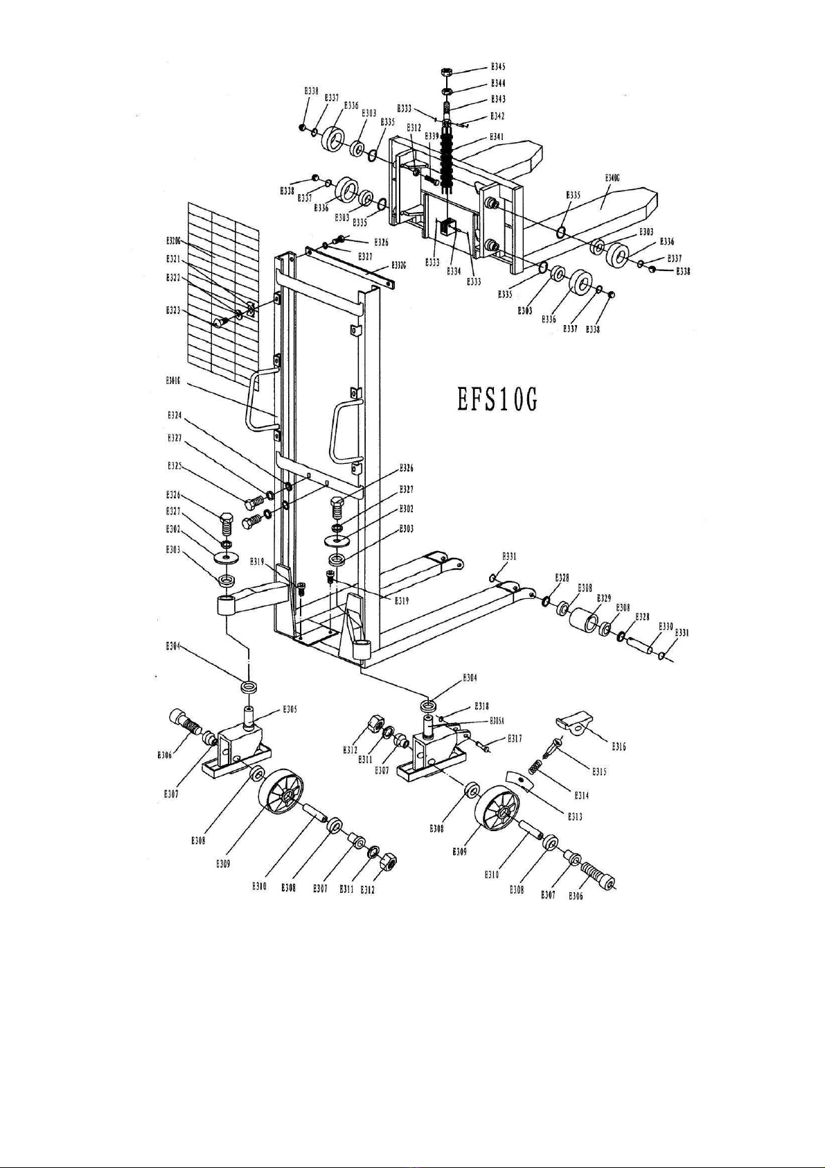
Mast Part List for EFS10G
No. Description
Qty No. Description
Qty
E301G Mast 1 E325 Screw 2
E302 Cover 2 E326 Screw 4
E303 Bearing 6 E327 Elastic Washer 4
E304 Bearing 2 E328 Washer 4
E305 Frame of Wheel 1 E329 Loading Roller 2
E305A Frame of Wheel
With Brake 1 E330 Shaft of Roller 2
E306 Screw 2 E331 Locking Ring 4
E307 Washer 4 E332G Linking Plate 1
E308 Bearing 8 E333 Cotter Pin 4
E309 Wheel 2 E334 Pin with Hole 1
E310 Sleeve 2 E335 Locking Ring 4
E311 Elastic Washer 2 E336 Roller 4
E312 Nut 4 E337 Locking Ring 4
E313 Brake 1 E338 Steel Ball 4
E314 Spring 1 E339 Bolt 4
E315 Pushing Bolt 1 E340G Fork 1
E316 Pedal 1 E341 Chain 1
E317 Shaft 1 E342 Pin with Hole 1
E318 Locking Ring 1 E343 Screw 1
E319 Screw 2 E344 Nut 1
E320G Reticulation 1 E345 Nut 1
E321 Clip 6
E322 Washer 6
E323 Screw 6
E324 Washer 2

15

16
Mast Part List for EFS10
No. Description
Qty No. Description
Qty
E301 Mast 1 E325 Screw 2
E302 Cover 2 E326 Bolt 4
E303 Bearing 6 E327 Elastic Washer 4
E304 Bearing 2 E328 Washer 4
E305 Frame of Wheel 1 E329 Loading Roller 2
E305A Frame of Wheel
With Brake 1 E330 Shaft of Roller 2
E306 Screw 2 E331 Locking Ring 4
E307 Washer 4 E332 Linking Plate 1
E308 Bearing 8 E333 Cotter Pin 4
E309 Wheel 2 E334 Pin with Hole 1
E310 Sleeve 2 E335 Locking Ring 4
E311 Elastic Washer 2 E336 Roller 4
E312 Nut 4 E337 Locking Ring 4
E313 Brake 1 E338 Steel Ball 4
E314 Spring 1 E339 Bolt 4
E315 Pushing Bolt 1 E340 Fork 1
E316 Pedal 1 E341 Chain 1
E317 Shaft 1 E342 Pin with Hole 1
E318 Locking Ring 1 E343 Screw 1
E319 Screw 2 E344 Nut 1
E320 Reticulation 1 E345 Nut 1
E321 Clip 6 E346 Nut 3
E322 Washer 6 E347 Stock 1
E323 Screw 6
E324 Washer 2

17

18
Mast Part List for EFS05
No. Description
Qty No. Description
Qty
E380 Mast 1 E328 Washer 4
E381 Screw 8 E329 Loading Roller 2
E382 Washer 8 E330 Shaft of Roller 2
E383 Frame of Wheel 1 E331 Locking Ring 4
E383A Frame of Wheel
With Brake 1 E332 Linking Plate 1
E306 Screw 2 E333 Cotter Pin 4
E384 Washer 4 E334 Pin with Hole 1
E308 Bearing 12 E387 Locking Ring 4
E385 Wheel 2 E388 Roller 4
E386 Sleeve 2 E389 Locking Ring 4
E311 Elastic Washer 2 E390 Steel Ball 4
E312 Nut 2 E391 Screw 4
E319 Screw 2 E392 Fork 2
E320 Reticulation 1 E393 Chain 1
E321 Clip 6 E394 Stock 1
E322 Washer 6 E342 Pin with Hole 1
E323 Screw 6 E343 Screw 1
E324 Washer 2 E344 Nut 1
E325 Screw 2 E345 Nut 1
E326 Screw 2 E346 Nut 15
E327 Elastic Washer 10

19
This manual suits for next models
4
Table of contents
Other Noblift Forklift manuals


