Toyota 8FBCU 20 Operating instructions

8FBCU 20, 25, 28, 30, 32
8FBCHU 25
VOL. 1
Pub. No. CU346

SECTION INDEX
Sections indicated by solid characters are included in this manual.
Sections indicated by half-tone characters: See vol. 2.
NAME SECTION
GENERAL 0
BATTERY 1
CONTROL SYSTEM 2
MULTI-FUNCTION DISPLAY 3
TROUBLESHOOTING 4
MOTOR 5
DRIVE UNIT 6
FRONT AXLE 7
REAR AXLE 8
STEERING 9
BRAKE 10
BODY 11
MATERIAL HANDLING SYSTEM 12
MAST 13
CYLINDER 14
OIL PUMP 15
OIL CONTROL VALVE 16
SAS FUNCTIONS 17
APPENDIX 18
Sec Index.fm 1 ページ 2010年3月31日 水曜日 午後4時21分

0-1
GENERAL
0
0
Page Page
EXTERIOR VIEWS .......................... 0-2
VEHICLE MODEL............................ 0-3
FRAME NUMBER............................ 0-4
HOW TO USE THIS MANUAL ..... 0-5
EXPLANATION METHOD ................ 0-5
TERMINOLOGY................................ 0-6
ABBREVIATIONS ............................. 0-6
SI UNITS ........................................... 0-7
OPERATIONAL TIPS ..................... 0-8
JACK-UP POINT ........................... 0-10
HOISTING THE VEHICLE ........... 0-11
CAUTION FOR TOWING............. 0-11
ATTENTIVE POINTS ON SAS ... 0-12
CIRCUIT TESTER ......................... 0-13
STANDARD BOLT & NUT
TIGHTENING TORQUE............. 0-15
BOLT STRENGTH CLASS
IDENTIFICATION METHOD ......... 0-15
PRECOAT BOLTS......................... 0-18
HIGH PRESSURE HOSE FITTING
TIGHTENING TORQUE............. 0-18
WIRE ROPE SUSPENSION
ANGLE LIST................................. 0-19
SAFE LOAD FOR EACH
WIRE ROPE SUSPENSION
ANGLE........................................... 0-19
COMPONENTS WEIGHT ............ 0-20
RECOMMENDED LUBRICANT
QUANTITY & TYPES ................. 0-20
LUBRICATION CHART................ 0-21
PERIODIC MAINTENANCE........ 0-22
PERIODIC REPLACEMENT OF
PARTS AND LUBRICANTS ..... 0-27
sec00.book 1 ページ 2010年4月14日 水曜日 午後6時29分

0-2
EXTERIOR VIEWS
0
sec00.book 2 ページ 2010年4月14日 水曜日 午後6時29分

0-3
0
VEHICLE MODEL
Model
Code Load Capacity Vehicle Model Voltage Remarks
20 4000 lbs 8FBCU20 36V/48V
25 5000 lbs 8FBCU25 ↑
8FBCHU25 ↑
28 5500lbs 8FBCU28 ↑
30 6000 lbs 8FBCU30 ↑
32 6500 lbs 8FBCU32 ↑USA·CANADA·MEXICO only
sec00.book 3 ページ 2010年4月14日 水曜日 午後6時29分

0-4
FRAME NUMBER
Frame No. Punching Position
*: EEC spec.
Vehicle Model Punching format
8FBCU20 8FBCU25-60011
* 8FBCU25 60011
8FBCU25
8FBCHU25 8FBCHU25-60011
8FBCU28 8FBCU28-60011
* 8FBCU28 60011
8FBCU30 8FBCU32-60011
* 8FBCU32 60011
8FBCU32
Punching position
sec00.book 4 ページ 2010年4月14日 水曜日 午後6時29分

0-5
0
HOW TO USE THIS MANUAL
EXPLANATION METHOD
1. Operation procedure
Example of description in pattern B
DISASSEMBLY·INSPECTION·REASSEMBLY
Tightening torque unit T = N·m (kgf·cm) [ft·lbf]
Disassembly Procedure
1 Remove the cover. [Point 1]
2 Remove the bushing. [Point 2]
3 Remove the gear.
Point Operations
[Point 1]
Disassembly:
Put a match mark when removing the pump cover.
[Point 2]
Inspection:
Measure the bush inside diameter.
Limit: 19.12 mm (0.7528 in)
• Step Nos. are partially sometimes omitted in
illustrations.
• When a part requiring tightening torque
instruction is not indicated in the illustration,
the part name is described in the illustration
frame.
T = 46.1 to 48.1
(470 to 490)
[34.0 to 35.5]
ÃOperation explained later
Ã
Explanation of key point for operation with an illustration
sec00.book 5 ページ 2010年4月14日 水曜日 午後6時29分

0-6
2. How to read components figures (Example)
3. Matters omitted in this manual
This manual omits description of the following jobs, but perform them in actual operation:
(1) Cleaning and washing of removed parts as required
(2) Visual inspection (partially described)
TERMINOLOGY
Caution:
Important matters of which negligence may cause hazards on human body. Be sure to observe
them.
Note:
Important items of which negligence may cause breakage or breakdown, or matters in operation
procedure requiring special attention.
Standard: Values showing allowable range in inspection and adjustment.
Limit: Maximum or minimum allowable value in inspection or adjustment.
ABBREVIATIONS
Abbreviation (code) Meaning Abbreviation (code) Meaning
ASSY Assembly RR Rear
ATT Attachment SAE Society of Automotive
Engineers (USA)
EHPS
Electronically controlled
fully hydraulic power
steering
SAS System of active stability
FHPS Fully hydraulic power
steering SOL Solenoid
LH Left hand SST Special service tool
FR Front STD Standard
OPS Operator Presence
Sensing T= Tightening torque
OPT Option {{T Number of teeth ({{)
O/S Oversize U/S Undersize
PS Power steering W/ With
RH Right hand L/ Less
3201
FIG number in parts catalog
(1) The components figure uses the illustration
in the parts catalog for the vehicle model.
Please refer to the catalog for checking the
part name.
The number at the right shoulder of each
components figure indicates the Fig.
number in the parts catalog.
(2) Refer to the parts catalog for the latest
information.
sec00.book 6 ページ 2010年4月14日 水曜日 午後6時29分

0-7
SI UNITS
Meaning of SI
This manual uses SI units. SI represents the International System of Units, which was established to unify the various
systems of units used in the past for smoother international technical communication.
New Units Adopted in SI
<Reference>
* 1: X represents the value in SI units as converted from 1 [in conventional units], which can be used as the
rate for conversion between conventional and SI units.
* 2: In the past, kilogram [kg] representing mass was often used in place of weight kilogram [kgf], which
should be used as the unit of force.
Conversion between Conventional and SI Units
Equation for conversion
When converting, change the unit of the value in conventional or SI units to the one in the conversion rate
column in the table above before calculation. For example, when converting 100 W to the value in
conventional unit PS, first change it to 0.1 kW and divide by the conversion rate 0.735499.
Item New unit Conventional unit Conversion rate*1 (1 [conventional unit] = X [SI unit])
Force*2N (newton) kgf 1 kgf = 9.80665 N
Torque*2
(Moment) N·m kgf·cm 1 kgf·cm = 9.80665 N·m
Pressure*2Pa (pascal) kgf/cm21 kgf/cm2= 98.0665 kPa = 0.0980665 MPa
↑↑mmHg 1 mmHg = 0.133322 kPa
Revolving speed rpm rpm 1 rpm = 1 r/min
Spring constant*2N/mm kgf/mm 1 kgf/mm = 9.80665 N/mm
Volume l cc 1 cc = 1 ml
Power W PS system 1 PS = 0.735499 kW
Heat quantity W·h cal 1 kcal = 1.16279 W·h
Specific fuel
consumption g/W·h g/PS·h 1 g/PS·h = 1.3596 g/kW·h
Value in SI unit = Conversion rate ×Value in conventional unit Conversion rate: Figure corresponding to X in the
conversion rate column in the table above
Value in conventional unit = Value in SI unit ÷Conversion rate
sec00.book 7 ページ 2010年4月14日 水曜日 午後6時29分

0-8
OPERATIONAL TIPS
1. Safe operation
(1) After jacking up, always support with wooden blocks or rigid stands.
(2) When hoisting the vehicle or its heavy component, use wire rope(s) with a sufficient reserve in load
capacity.
(3) Always disconnect the battery plug before the inspection or servicing of electrical parts.
2. Tactful operation
(1) Prepare the mechanic tools, necessary measuring instruments (circuit tester, megger, oil pressure
gauge, etc.) and SSTs before starting operation.
(2) Before disconnecting wiring, always check the cable color and wiring state.
(3) When overhauling functional parts, complicated portions or related mechanisms, arrange the parts
neatly to prevent confusion.
(4) When disassembling and inspecting such a precision part as the control valve, use clean tools and
operate in a clean location.
(5) Follow the described procedures for disassembly, inspection and reassembly.
(6) Replace, gaskets, packing and O-rings with new ones each time they are disassembled.
(7) Use genuine Toyota parts for replacement.
(8) Use specified bolts and nuts. Observe the specified tightening torque at the time of reassembly.
(Tighten to the center of the specified tightening torque range.)
If no tightening torque is specified, tighten the bolt or nut according to the standard tightening
torque table.
3. Protection of functional parts
(1) Thoroughly check each connector for any failure in or imperfect connection before reconnecting the
battery plug after the end of vehicle inspection or maintenance.
Failure in or imperfect connection of connectors related to controllers, especially, may
damage elements inside the controllers.
4. Confirming defect status
Do not start immediate disassembly or replacement, but first confirm if such disassembly or
replacement is actually needed.
5. Handling of waste fluid, etc.
When draining waste fluid from the vehicle, always receive it with an appropriate container.
Since careless or arbitrary discharge or disposal of oil, fuel, coolant, oil filter, battery or any other
harmful substance may cause adverse affect to people or environmental destruction, sort each waste
and always ask an authorized contractor for appropriate disposal.
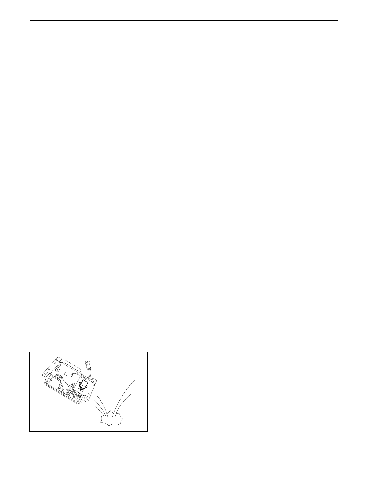
6. Handling of electronic parts
(1) Never apply impacts to electronic parts such as a
microcomputer or relay.
(2) Never let electronic parts be exposed to a high
temperature or humidity.
(3) Do not touch connector pins since they may be
deformed or be damaged due to static electricity.
sec00.book 8 ページ 2010年4月14日 水曜日 午後6時29分

0-9
7. Disconnect the battery plug
When unplugging the battery plug, use the grip. Do not pull up the cable.
For example:
sec00.book 9 ページ 2010年4月14日 水曜日 午後6時29分

0-10
JACK-UP POINT
Strictly observe the following instructions when jacking up the vehicle.
• When a load is on the fork, unload it and park the vehicle on a flat floor. Be sure to avoid an inclined or
rugged place.
• Use a jack with ample capacity and jack up the vehicle at the specified jack-up point. Jacking up at any
other point will be dangerous.
• Never operate while the vehicle is held with a jack. Always support the frame with a wooden block after
jacking up.
• In any case, never let a part of the body (including hands and feet) be under the jacked-up vehicle.
:
Jack-up point
:
Wooden block or stand
setting point
sec00.book 10 ページ 2010年4月14日 水曜日 午後6時29分

0-11
HOISTING THE VEHICLE
When hoisting the vehicle, use the mast hook on the front of
the vehicle and a wire net on the rear wheel.
Caution:
• Use wire ropes having sufficient strength.
• Never hoist the forklift by the weight hook holes or
head guard.
CAUTION FOR TOWING
1. When towing the forklift, always lift the rear wheels away
from the ground.
2. The traveling speed in towing must not exceed the
maximum traveling speed of the forklift.
3. Always set the key switch to OFF and the direction
switch to the neutral position before starting towing.
In case of towing by connection with a wire rope with the
operator on the forklift, however, set the key switch to
ON (PS operation) and always set the direction switch to
the neutral position.
4. Before towing, either remove the fork or take an action
to prevent fork contact with the ground due to bounding.
sec00.book 11 ページ 2010年4月14日 水曜日 午後6時29分

0-12
ATTENTIVE POINTS ON SAS
1. Reference should be made to seperate manual “New Model Feature 8FBCU20 to 32 Pub. No.PU319”
for the explanations of SAS functions and operations.
2. Read Section 17 “SAS Precautions for Repair” on Page 17-9 in this repair manual in advance.
3. Whenever the repair or replacement is performed to the place where relative to SAS function, maching
procedure by which the SAS regain proper function must be performed. (See 17-18)
4. The warning on the SAS caution label must be confirmed when the modification or change is such as
to change the original specification.
If improper, change the label. (See Page 17-22)
5. Care should always be exercised for safety operation whenever you operate the truck.
Make distinction between the SAS featured trucks and those of none, because the control features are
different.
6. The SAS oil control valves comprise many precision valves. Since dirty or contaminated hydraulic oil
will adversely affect the functions of these valves, always wash the parts clean at the time of
installation after disassembly or for replacement of hydraulic parts (valves, piping, etc.). Periodic
replacement of the hydraulic oil is very important.
7. Since this vehicle uses high-precision electronic devices, modification of electrical parts may cause
faults. Always use genuine Toyota parts when replacing or installing electrical parts (auxiliary
equipment, optional parts, etc.)
sec00.book 12 ページ 2010年4月14日 水曜日 午後6時29分

0-13
CIRCUIT TESTER
Circuit testers are available in both the analog and digital types. They should be used selectively according
to the purpose of measurement.
Analog type: This type is convenient for observing movement during operation, but the measured value
should only be used for reference or rough judgement.
Digital type: Fairly accurate reading is possible, but it is difficult to observe the variation or movement.
1. Difference in measurement results with the digital type and analog type
* The result may be different between measurements with the analog type and digital type.
Always use a circuit tester according to its operation manual.
Cautions when the polarities are different between the analog type and digital type are described
below.
(1) Analog circuit tester
Measurement result example
Tester range: kΩrange
(2) Digital circuit tester
Measurement result example
Tester range: MΩrange
Forward direction Reverse direction
Analog type
Forward Continuity exists
11 kΩ
Reverse No continuity
∞
Forward direction Reverse direction
Digital type
Forward No continuity
1
Reverse Continuity exists
2 MΩ
sec00.book 13 ページ 2010年4月14日 水曜日 午後6時29分

0-14
2. Difference in result of measurement with circuit tester
The circuit tester power supply voltage depends on the tester type. 1.5 V, 3.0 V or 6.0 V is used.
The resistance of a semiconductor such as a diode varies with the circuit tester power supply voltage.
The diode characteristics are shown in the figure below.
The resistance values of the same semiconductor measured
with two types of circuit testers having different power supply
voltages are different.
This manual describes the results of measurement with a
circuit tester whose power supply voltage is 3.0 V.
3. Difference in measurement result by measurement range (analog type)
In the analog type circuit tester, changing the measurement range switches over the internal circuit to
vary the circuit resistance. Even when the same diode is measured, the measurement result varies
with the measurement range.
Always use the range described in the repair manual for
measurement.
0
1
2
3
4
5
6
0.1 0.2 0.3 0.4 0.5 0.6 0.7 0.8
(V)Forward voltage
Germanium
diode
(mA)
Forward current
Silicon
diode
Resistor Meter
0Ω
Variable resistor
Resistor
Resistor
Range:×10
Range:×1
Power source: 1.5V
Red Black
(SW1)
Current flow
sec00.book 14 ページ 2010年4月14日 水曜日 午後6時29分

0-15
STANDARD BOLT & NUT TIGHTENING TORQUE
Standard bolt and nut tightening torques are not indicated.
Judge the standard tightening torque as shown below.
1. For tightening torque of hexagon head bolt, welded bolt and stud bolt with the standard bearing surface, identify
bolt class based on the below chart and then determine using the tightening torque table.
2. For tightening torque of hexagon flange bolts, identify bolt class based on the below chart and then determine
using the tightening torque table.
3. For tightening torque of nuts, check the mating bolt and use the method 1.
BOLT STRENGTH CLASS IDENTIFICATION METHOD
Identification by Bolt Shape
Shape and class Class
Hexagon head bolt
Bolt head No.
4 = 4T
5 = 5T
6 = 6T
7 = 7T
8 = 8T
No mark 4T
Two protruding lines 5T
Three protruding lines 7T
Four protruding lines 8T
Welded bolt 4T
Stud bolt
No mark 4T
Grooved 6T
sec00.book 15 ページ 2010年4月14日 水曜日 午後6時29分

0-16
Identification by Part No.
Tightening Torque Table
Part No. Shape
Hexagon head bolt
Stud bolt
Class Diameter
mm
Pitch
mm
Specified torque
N·m kgf·cm ft·lbf
4T
6
8
10
12
14
16
1.0
1.25
1.25
1.25
1.5
1.5
5.4
13
25
47
75
113
55
130
260
480
760
1150
4
9
19
35
55
83
5T
6
8
10
12
14
16
1.0
1.25
1.25
1.25
1.5
1.5
6.5
16
32
59
91
137
65
160
330
600
930
1400
5
12
24
43
67
101
6T
6
8
10
12
14
16
1.0
1.25
1.25
1.25
1.5
1.5
7.8
19
39
72
108
172
80
190
400
730
1100
1750
6
14
29
53
80
127
7T
6
8
10
12
14
16
1.0
1.25
1.25
1.25
1.5
1.5
11
25
52
95
147
226
110
260
530
970
1500
2300
8
19
38
70
108
166
8T
6
8
10
12
14
16
1.0
1.25
1.25
1.25
1.5
1.5
12
29
61
108
172
265
120
300
620
1100
1750
2700
9
22
45
80
127
195
Length (mm)
Diameter (mm)
Class
Diameter
Length
Length (mm)
Diameter (mm)
Class
Diameter
Length
sec00.book 16 ページ 2010年4月14日 水曜日 午後6時29分
This manual suits for next models
5
Table of contents
Other Toyota Forklift manuals

Toyota
Toyota 8FGU15 User manual

Toyota
Toyota 8FBE18T User manual

Toyota
Toyota 7FG 10 Operating instructions

Toyota
Toyota 50-4FD100 User manual

Toyota
Toyota 5FGC Series User manual

Toyota
Toyota 7FBCU 15-55 User manual

Toyota
Toyota BT Levio W Series User manual

Toyota
Toyota 7FBE10 User manual

Toyota
Toyota 02-8FGF15 User manual

Toyota
Toyota 8FG35N User manual