Noblift LPT15 User manual

NOBLELIFT EQUIPMENT
Service & Maintenance Manual
LPT15 Power Pallet Truck
V-LPT20-01.00 Date: 2011-02-24

1
CONTENTS
FOREWORD............................................................................................................................................2
1. GENERAL.........................................................................................................................................3
1.1 INTRODUCTION – MAINTENANCE SAFETY PRECAUTIONS..............................................3
1.2 MEASUREMENT CONVERSIONS..........................................................................................7
2. SPECIFICATION.............................................................................................................................11
2.1 LOCATION OF COMPONENTS ............................................................................................11
2.2 SPECIFICATION SHEETS.....................................................................................................12
2.3 LUBRICATION.......................................................................................................................13
3. ELECTRIC SYSTEM.......................................................................................................................14
3.1 ELECTRIC DIAGRAM............................................................................................................14
3.2 INSTALLATION OF ELECTRICAL........................................................................................17
3.3 DRIVE WHEEL.......................................................................................................................18
3.4 POWER UNIT.........................................................................................................................18
3.5 BATTERY...............................................................................................................................18
3.6 CHARGER .............................................................................................................................20
3.7 CURTIS CONTROLLER ........................................................................................................23
3.8 BATTERY INDICATOR..........................................................................................................31
3.9 REPLACING THE ELECTRIC PARTS ..................................................................................33
3.10 TOOL FOR REPAIRING THE PIN OF ELECTRIC PLUG......................................................37
4. HYDRAULIC SYSTEM....................................................................................................................38
4.1 REPLACING OF POWER UNIT.............................................................. 错误!未定义书签。
4.2 REPLACING OF CYLINDER...............................................................................................41
5. DRIVE WHEEL................................................................................................................................44
5.1 REPLACING THE WHEEL ..................................................................................................45
5.2 REPLACING THE CARBON BRUSH KIT...........................................................................45
5.3 REPLACING THE BRAKE...................................................................................................47
5.4 THE BRAKE CLEARANCE ADJUSTMENT........................................................................48
6. CONTROL HANDLE.......................................................................................................................50
6.1 REPLACING OF THE CONTROL HANDLE..........................................................................51
6.2 REPLACING OF THE AIR SPRING AND MICRO SWITCH..................................................53
7. CASTER WHEEL............................................................................................................................53
7.1 REPLACING OF THE CASTER WHEEL...............................................................................54
7.2 ADJUSTING THE PRESSURE FOR THE DRIVE WHEEL ...................................................54
8. TROUBLE DIAGNOSTICS.............................................................................................................55
8.1 MAINTENANCE LIST ............................................................................................................55
8.2 TROUBLE SHOOT.................................................................................................................56

2
FOREWORD
Proper operation, maintenance, troubleshooting and repairs are necessary to preserve the performance
of the pallet truck over along period of time and ensure that fault and breakdowns do not occur. The
object of this service manual is to provide the information necessary especially in connection with the
performance of inspections and repairs mainly in the maintenance areas.
The majority of this pallet truck consists of steel, it can be completely recycled. Waste
material in conjunction with repairs, maintenance, cleaning or scrapping, must be collected and disposed
of in an environment-friendly way and in accordance with the directives of respective countries. Such
work must be carried out in areas intended for this purpose. Recyclable material should be taken care of
by specialized authorities. Environmentally hazardous waste, such as oil filters, batteries and electronics,
will have a negative effect on the environment, or health, if handled incorrectly.
All of the information reported herein is based on data available at the moment of
printing. Our products are constantly being developed and renewed, we reserves the right to modify our
own products at any moment without prior notice and incurring in any sanction. So, it is suggested to
always verify possible updates.
3
1. GENERAL
1.1 INTRODUCTION – MAINTENANCE SAFETY PRECAUTIONS
Careless performing of the easy work may cause injuries. Take care to always perform work safely, at
least observing the following. It is of utmost importance that maintenance personnel pay strict attention
to these warnings and precautions to avoid possible injury to themselves or others, or damage to the
equipment. A maintenance program must be followed to ensure that the machine is safe to operate.
The specific precautions to be observed during maintenance are inserted at the appropriate point in the
manual. These precautions are those that apply when servicing hydraulic and larger machine
component parts.
MODIFICATION OF THE MACHINE WITHOUT CERTIFICATION BY A
RESPONSIBLE AUTHORITY THAT THE MACHINE IS AT LEAST AS SAFE AS ORIGINALLY
MANUFACTURED, IS A SAFETY VIOLATION.
SINCE THE MACHINE MANUFACTURER HAS NO DIRECT CONTROL OVER THE
FIELD INSPECTION AND MAINTENANCE, SAFETY IN THIS AREA RESPONSIBILITY OF THE
OWNER OR OPERATOR.
FAILURE TO COMPLY WITH SAFETY PRECAUTIONS LlSTED IN THIS SECTION
MAY RESULT IN MACHINE DAMAGE, PERSONNEL INJURY OR DEATH AND IS A SAFETY
VIOLATION.
When carrying out any operation or maintenance, have trained and experienced personnel carry out
the work.
When carrying out any operation or maintenance, carefully read out Operation and Maintenance
Manual.
Read all the precautions given on the decals which are fixed to the machine.
Be sure you fully understand the contents of the operation. It is important to prepare necessary tools
and parts and to keep the machine.
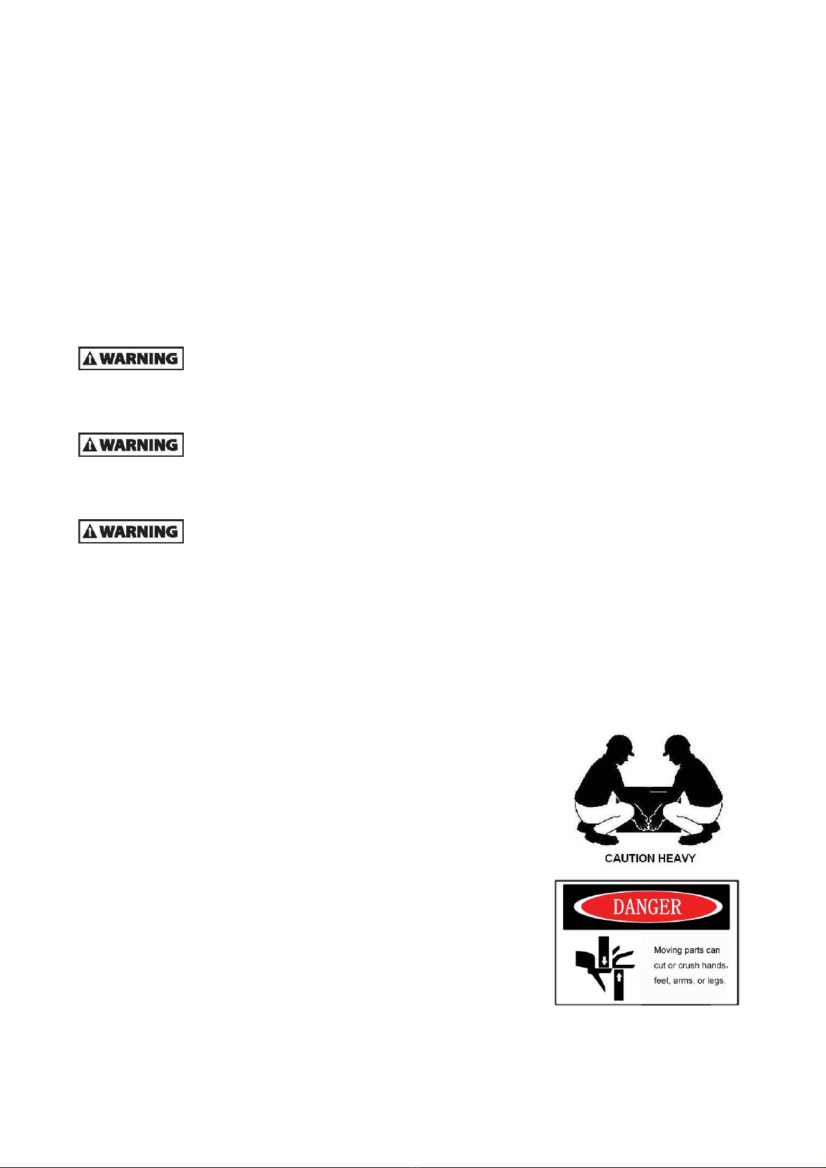
Your safety, and that of others , is the first consideration when
engaging in the maintenance of equipment. Always be conscious of
weight. Never attempt to move heavy parts without the aid of a
mechanical device. Do not allow heavy objects to rest in an
unstable position. When raising a portion of the equipment, ensure
that adequate support is provided.

4
It should be noted that the machines hydraulic systems operate at
extremely high potentially dangerous pressures. Every effort should
be made to relieve any system pressure prior to disconnecting or
removing any portion of the system. Relieve system pressure by
cycling the applicable control lowering button several times with the
engine(motor) stopped and ignition on, to direct any line pressure
back into the reservoir. Pressure feed lines to system components
can then be disconnected with minimal fluid loss.
Remove all rings, watches and jewelery when performing any maintenance.
Wear well-fitting helmet, safety shoes and working Clothes When
drilling grinding or hammering always. Wear protective goggles.
Always do up safety clothes properly so that they do. Not catch on
protruding parts of machines. Do not wear oily clothes. When
checking, always release battery plug. DO NOT WEAR LONG
HAIR UNRESTRAINED, OR LOOSE-FITTING CLOTHING AND
NECKTIES WHICH ARE APT TO BECOME CAUGHT ON OR
ENTANGLED IN EQUIPMENT.
During maintenance do not allow any unauthorized person, to
stand near the machine.
Flames should never be used instead of lamps. Never use a buring
flame to check leaks or the level of oil or electrolyte.
Immediately remove any oil or grease on the floor of the operator’s
compartment or on the handrail. It is very dangerous if someone slips
while on the machine.
Always use the recommended pure oil or grease, and be sure to use clean containers.
Oil is a dangerous substance. Never handle oil, grease or oily
clothes in places where there is any fire or flame. As
preparation for use of fire extinguishers and other fire- fighting
equipment.
Keep the battery away from fire hazards. The generated gases
are explosive.
Store all the oils in a specified place.
Keep the flammable things away from the machine. Do not
smoke in the working site.
Battery should always be disconnected during replacement of electrical components.

5
Always use the grades of grease and oil recommended by NOBLELIFT choose the viscosity
specified for the ambient temperature.
Exhaust gas is dangerous provide ventilation when working in a closed
space.
Avoid breathing dust that may be generated when handling components
containing asbestos fibers. Wear a gas mask if necessary.
When working on top of the machine, be careful not to lose your balance
and fall.
Hand a caution sign in the operator’s compartment (for example
“Do not start” of “Maintenance in progress”). This will prevent
anyone from starting or moving the machine by mistake.
When welding on the machine or working on the electical system,
ALWAYS turn the key switch OFF and remove the battery plug
from the battery. Park the machine on firm, flat ground. Lower the
fork to the min. height and stop the motor.
Sulfuric acid in battery electrolyte is poisonous. Ist is strong
enough to burn skin and eat holes in clothing. If you spill acid on
your clothes or skin, immediately flush it with large quantities of
water.
When working on the battery, wear goggles or safety glasses. If
splashed into the eyes, flush with water and get medical attention
immediately.
Battery terminals touched by metal objects can cause short circuit
and burn you. Keep tools away from the terminals.
When disassembling and assembling the battery, make sure that
the battery terminals (+, –) are correctly connected.
If water gets into the electrical system, abnormal operation or
failure can result. Do not use water or steam on sensors, connectors
and instruments in the cab.
Do not handle electrical equipment while wearing wet gloves, or in wet
places, as this can cause electric shock.
When working with others, choose a group leader and work according to his instructions. Do not
perform any maintenance beyond the agreed work.

6
Unless you have special instructions to the contrary, maintenance should always be carried out with
the motor stopped. If maintenance is carried out with the motor running, there must be two men
present : one operating the pallet truck and the other one performing the maintenance. In such a
case, never touch any moving part.
Before making adjustment, lubricating or performing any other maintenance, shut off all power
controls.
When removing parts containing O-ring Gaskets or seal. Make sure clean the mounting surface and
replace with new sealing parts.
Thoroughly clean the machine. In particular, be careful to clean the grease fittings and the area
around the dipsticks. Be careful not to let any dirt or dust into the system.
Use only approved, nonflammable cleaning solvents.
When changing the oil or fitter, check the drained oil and filter for any signs of excessive metal
particles or other foreign materials.
Always use NOBLELIFT genuine parts for replacement. ENSURE REPLACEMENT PARTS OR
COMPONENTS ARE IDENTICAL OR EQUIVALENT TO ORIGINAL PARTS OR COMPONENTS.
When checking an open gear case, there is a risk of dripping things in. Before removing the covers
to inspect such cases, empty everything from your pockets. Be particularly careful to remove
wrenches and nuts.

7
1.2 MEASUREMENT CONVERSIONS
Length
Unit cm m km in ft yd mile
cm 1 0.01 0.00001 0.3937 0.03281 0.01094 0.000006
m 100 1 0.001 39.37 3.2808 1.0936 0.00062
km 100000 1000 1 39370.7 3280.8 1093.6 0.62137
in 2.54 0.0254 0.000025 1 0.08333 0.02777 0.000015
ft 30.48 0.3048 0.000304 12 1 0.3333 0.000189
yd 91.44 0.9144 0.000914 36 3 1 0.000568
mile 160930 1609.3 1.6093 63360 5280 1760 1
1mm=0.1cm, 1m=0.001mm
Area
Unit cm2 m2 km2 a ft2 yd2 in2
cm2 1 0.0001 – 0.000001 0.001076 0.000012 0.155000
m2 10000 1 0.000001 0.01 10.764 1.1958 1550.000
km2 – 1000000 1 10000 1076400 1195800 –
a 0.01 100 0.0001 1 1076.4 119.58 –
ft2 – 0.092903 – 0.000929 1 0.1111 144.000
yd2 – 0.83613 – 0.008361 9 1 1296.00
in2 6.4516 0.000645 – – 0.006943 0.000771 1
1ha=100a, 1mile2=259ha=2.59km2
Volume
Unit cm3 = cc m3 l in3 ft3 yd3
cm3 = m l 1 0.000001 0.001 0.061024 0.000035 0.000001
m3 1000000 1 1000 61024 35.315 1.30796
l 1000 0.001 1 61.024 0.035315 0.001308
in3 16.387 0.000016 0.01638 1 0.000578 0.000021
ft3 28316.8 0.028317 28.317 1728 1 0.03704
yd3 764529.8 0.76453 764.53 46656 27 1
1gal(US)=3785.41 cm3=231 in3=0.83267gal(US)
Weight
Unit g kg t oz lb
g 1 0.001 0.000001 0.03527 0.0022
kg 1000 10 0.001 35.273 2.20459
t 1000000 1000 1 35273 2204.59
oz 28.3495 0.02835 0.000028 1 0.0625
lb 453.592 0.45359 0.000454 16 1
1 tonne(metric)=1.1023 ton(US)=0.9842 ton(UK)

8
Pressure specifications
Unit kgf/cm2 bar Pa=N/m2 kPa lbf/in2 lbf/ft2
kgf/cm2 1 0.98067 98066.5 98.0665 14.2233 2048.16
bar 1.01972 1 100000 100 14.5037 2088.6
Pa=N/m2 0.00001 0.00001 1 0.001 0.00015 0.02086
kPa 0.01020 0.01 1000 1 0.14504 20.886
lbf/in2 0.07032 0.0689 6894.76 6.89476 1 144
lbf/ft2 0.00047 0.00047 47.88028 0.04788 0.00694 1
kgf/cm2=735.56 Torr(mmHg)=0.96784atm
Standard torque
The following charts give the standard torque specification of bolts and nuts.
Exceptions are given in sections of “Disassembly and Assembly”
METER TABLE
Classification 4T, 5T 10T
Bolt type
Bolt size Torque kgf · m (lbf · ft) Torque kgf · m (lbf · ft)
M4 0.2 ± 0.02 0.4 ± 0.04
M5 0.3 ± 0.03 0.8 ± 0.08
M6 0.5 ± 0.05 1.4 ± 0.14
M8 1.2 ± 0.12 3.3 ± 0.3
M10 2.3 ± 0.23 6.5 ± 0.7
M12 4.0 ± 0.4 11.3 ± 1.1
M14 6.4 ± 0.6 17.9 ± 1.8
M16 9.5 ± 0.9 26.7 ± 2.7
M18 13.5 ± 1.4 38.0 ± 3.8
M20 18.6 ± 1.9 52.2 ± 5.2
M22 24.7 ± 2.5 69.4 ± 6.9
M24 32.1 ± 3.2 90.2 ± 9.0
M30 62.6 ± 6.3 176.1 ± 17.6
M36 108.2 ± 10.8 304.3 ± 30.4
M42 171.8 ± 17.2 483.2 ± 48.3
M45 211.3 ± 21.1 594.3 ± 50.4
10.9

9
INCH TABLE
4T, 5T 10T
Classification Bolt type
Bolt size Torque kgf · m (lbf · ft) Torque kgf · m (lbf · ft)
1/4 0.6 ± 0.06 1.7 ± 0.2
5/16 1.2 ± 0.12 3.0 ± 0.3
3/8 2.0 ± 0.20 5.6 ± 0.5
7/16 3.2 ± 0.32 8.9 ± 0.9
1/2 4.7 ± 0.47 13.4 ± 1.3
9/16 6.8 ± 0.68 19.0 ± 1.9
5/8 9.3 ± 0.93 26.1 ± 2.6
3/4 16.0 ± 1.60 45.1 ± 4.5
7/8 25.5 ± 2.55 71.6 ± 7.2
1 38.0 ± 3.80 106.9 ± 10.7
1-1/8 54.1 ± 5.41 152.2 ± 15.2
1-1/4 74.2 ± 7.42 208.9 ± 20.9
1-3/4 98.8 ± 9.88 277.8 ± 27.8
1-1/2 128.2 ± 12.82 360.7 ± 36.1
The torque specifications in above table shall not be applied to the bolts with nylon packings and nonferrous
metal washers, or the ones with specifically designated torque and standard.
H Newton meter : 1 N·m = 0.1kgf·m
TIGHTENING TORQUE OF SPLIT FLANGE BOLTS
The following torque shall be applied to the split flange bolts.
TorqueDiameter
(mm)
Flat width
(mm) kgf·m N·m
10 14 6.7 ± 0.7 66.7 ± 6.8
12 17 11.5 ± 1 112 ± 9.8
16 22 28.5 ± 3 279 ± 29

10
APPROXIMATE CONVERSIONS
SI Conv Non–SI Conv SI
Unit Factor Unit Factor Unit
Torque
newton meter (N·m) ×8.9 = ln·in ×0.113 = N·m
newton meter (N·m) ×0.74 = lb·ft. ×1.36 = N·m
newton meter (N·m) ×0.102 = kg·m ×7.22 = lb·ft.*
Pressure (Pa = N/m2)
kilopascal (kPa) ×4.0 = in. H2O ×0.249 = kPa
kilopascal (kPa) ×0.30 = in. Hg ×3.38 = kPa
kilopascal (kPa) ×0.145 = psi ×6.89 = kPa
(bar) ×14.5 = psi ×0.069 = bar*
(kg/cm2) ×14.22 = psi ×0.070 =
kf/
2
*
newton/mm2×145.04 = psi ×0.069 = bar*
megapascal (MPa) ×145 = psi ×0.00689 = MPa
(Pa=N·m2)
Power r (W = J/s)
kilowatt(kW) ×1.36 = PS (cv) ×0.736 = kW
kilowatt(kW) ×1.34 = HP ×0.746 = kW
kilowatt(kW) ×0.948 = Btu/s ×1.055 = kW
watt(W) ×0.74 = ft·lb/s ×1.36 = W
(W=J/s)
Energy (J = N·m)
kilojoule(kJ) ×0.948 = Btu ×1.055 = kJ
joule(J) ×0.239 = calorie ×4.19 = J
(J=N·m)
Velocity and Acceleration
meter per sec2(m/s2) ×3.28 = ft/s2×0.305 = m/s2
meter per sec (m/s) ×3.28 = ft/s ×0.305 = m/s
kilometer per hour (km/h) ×0.62 = mph ×1.61 = km/h
Horse Power/Torque
BHP ×5252 R.P.M. = TQ (lb·ft) TQ Z R.P.M. 5252 = B.H.P.
Temperature
°C = (°F–32) ÷ 1.8 °F= (°C Z 1.8) + 32
Flow Rate
liter/min (dm3/min) ×0.264 = US gal/minZ3.785 = l/min
Note : ( ) Non–SI Unit
11
2. SPECIFICATION
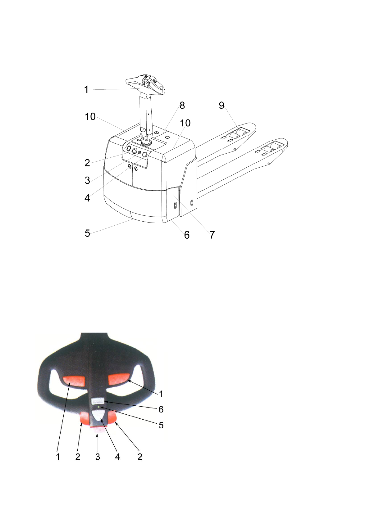
2.1 LOCATION OF COMPONENTS
1. Control Handle 6. Caster Wheel
2. Battery Indicator CURTIS 803 7. Pump Station
3. Start Key Switch 8. Lift Cylinder
4. Emergency Button 9. Load Roller
5. Drive Wheel 10. Battery
CONTROL HANDLE
1. Raise/Lower buttons – Rocker switches
adjusting fork height.
2. FWD/BWD/REV travel button –Control
variable speed by turning knob
3. Emergency Reverse button – Emergency
reverse button or commonly known as the belly
button switch
4. Horn button
5. Indicator light – Indicates high/low speed
status. Green indicates high speed, red
indicates slow speed.
6. Shift button – Shift button for high speed and
low speed

12
2.2 SPECIFICATION SHEETS
1.2 Model of manufacture LPT15
1.3 Power supply (electric, diesel, petrol, gas, mains electric
1.4 Type of operation (hand, pedestrian, stand on, rider pedestrian
1.5 Capacity / rated load Q KGs 1500
1.6 Load center distance C mm 600
1.8 Load distance X mm 963
Characteristics
1.9 Wheelbase Y mm 1217
2.1 Weight (including battery) KGs 286
2.2 Axle loadings laden drive end / load end KGs 760 / 1026
2.3 Axle loadings unloaded drive end / load end KGs 222 / 64
Weight
3.1 Tyres (rubber, Vulkollan, pneumatic, polyurethane) polyurethane
3.2 Tyre size Dia. x width drive end mm Φ252x89
3.3 Tyre size Dia. x width load end mm 2xΦ84x70
3.4 Castor wheels (dimensions) mm 2xΦ100x40
3.5 Wheels, number(x=drive wheel) 1x -2/ 4
3.6 Track width (front) drive end b10 mm 490
Wheels types
3.7 Trackwidth(rear) loadend b11 mm 360
4.4 Lift height h3 mm 120
4.9 Tiller height in neutrality position h14 mm 1235
4.15 Fork height lowered h13 mm 85
4.19 Overall length l1 mm 1590
4.20 Length to front face of fork l2 mm 440
4.21 Overall width b1 mm 700
4.22 Fork dimensions s/e/l mm 47 / 160 / 1150
4.25 Overall fork width b5 mm 520
4.32 Floor clearance, center of wheelbase m2 mm 34
4.34 Working aisle with 800x1200 pallet lengthwise Ast mm 1840
Dimensions
4.35 turning radius Wa mm 1480
5.1 Travel Speed laden / mph 5.0 / 5.2
5.2 Lifting speed laden / mm/s 27 / 35
5.3 Lowering speed laden / unloaded mm/s 42 / 27
5.8 Grade-ability laden / unloaded % 5 / 8
Performance
5.10 Brakes Electric-magnetic
6.1 Drive motor kw 0.75
6.2 Lifting motor kw 0.8
6.4 Battery voltage, normal capacity K5 V/Ah 2x12 / 80
6.5 Battery weight +/-5% KGs 48
Battery dimensions l /w / h mm 260 / 170 / 230
Electric motor
8.1 Type of drive control MOSFET Control
8.4 Sound level at driver’s ears dB(A) <70
Other
Turning angle °205

13
2.3 LUBRICATION
Hydraulic oil
Hydraulic oil must have anti-wear qualities at least. It is not advisable to mix oils of
different brands or types, as the may not contain the same required additives or be of
comparable viscosities.
Name: Thickened hydraulic oil.
ISO Viscosity Grade #40 #30
Characteristics unit
At 40OC 57 48
Viscosity At 50OC mm2/s 40 30
Viscosity index ≥150 ≥150
Flash point, Cleveland open cup OC ≥160 ≥160
Pour point, Max OC ≤-35 ≤-35
Density at 15 OC kg/m3861.5
Copper corrosion(100OC, 3h) degree ≤1 ≤1
Foaming (93.5 OC) ml / ml
≤30/0 ≤30/0
Vickers vane pump test, loss of mass (on vanes after 100h) mg ≤100 15.3
Diameter of wear spot, 1200 r/min, 294N, 30min, 75 OC mm ≤0.5 ≤0.5
The oil for gear box
Name: Extreme pressure lithium-based grease, 1#.
Characteristics unit
Worked Penetration, 0.1mm 310--340
Dropping point, OC ≥170
Extreme pressure (Timken OK) N ≥177
Similar viscosity (-10 OC, 10s-1) Pa.s ≤250
Corrosion preventive properties (52 OC, 48h) Grade 1
Wire points oil (100 OC, 24h) % ≤10
14
3. ELECTRICAL SYSTEM
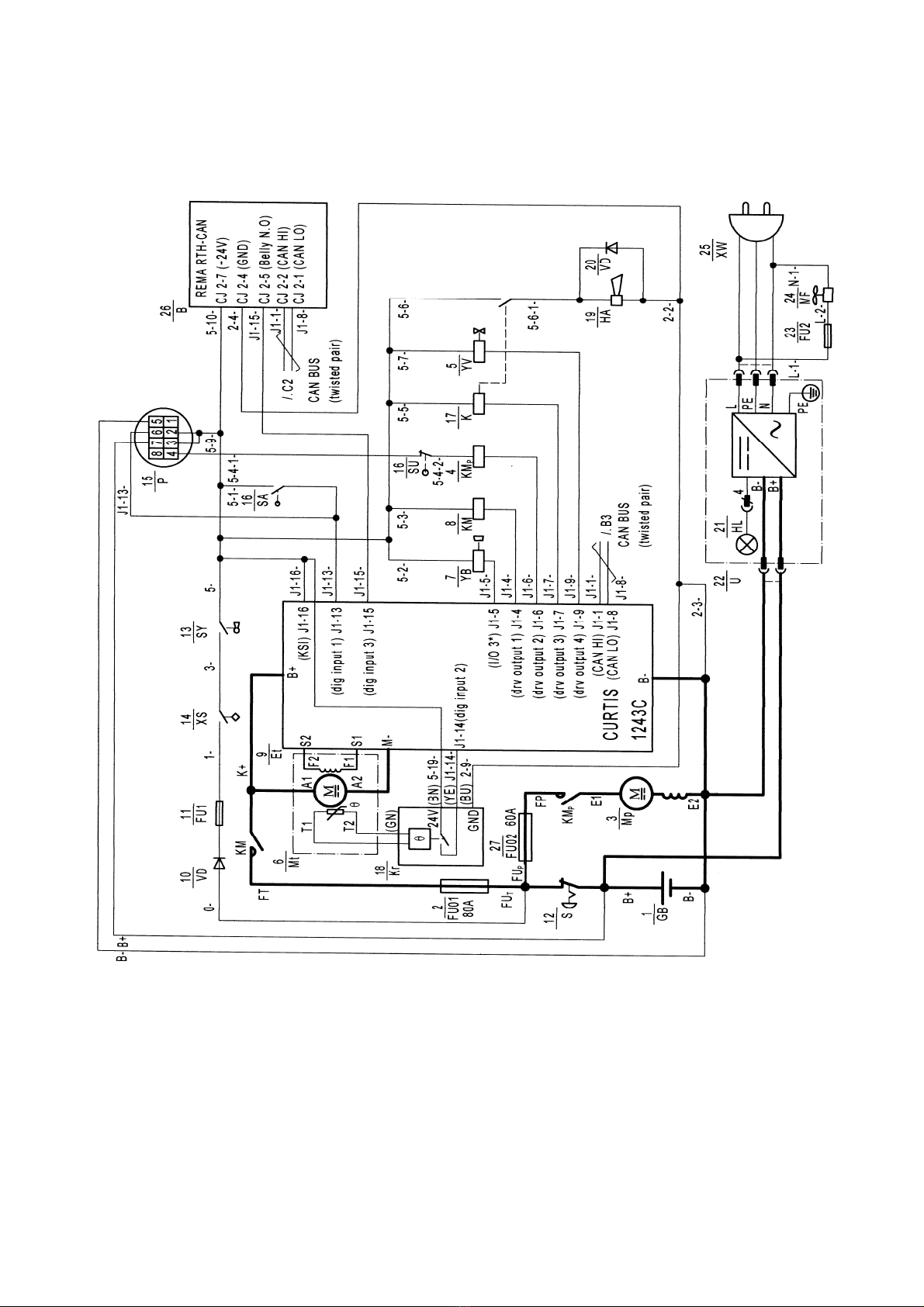
3.1 ELECTRICAL DIAGRAM
WIRING DIAGRAM
15
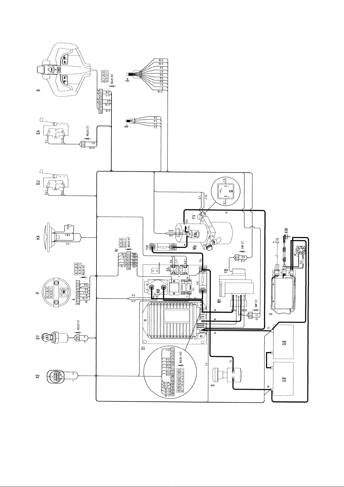
CONNECTION DIAGRAM
16
No. Code NL. Drawing No. Description Qty.
1 GB BQ-20 Battery – 2x12V/80Ah 1
2 FU01 DQ-38 Fuse, 80A 1
3 Mp WG-2-2 Motor for pump, DC24V/0.8kw 1
4 KMp WG-2-1 Relay for motor of pump, DC24V 1
5 YV WG-2-3 Lower magnet valve, DC24V 1
6 Mt WG-8-4 Motor for traction, DC24V/0.75kw 1
7 YB WG-8-11 Brake, DC24V 1
8 KM DQ-3 Main relay C100/120 DC24V 1
9 Et DQ-13 Controller CURTIS 1243C-4381 1
10 VD DQ-10 Diodes 1N5408 2
11 FU1 DQ-9 Fuse,10A 1
12 S DQ-48 Emergency button ZDK31-250 1
13 SY DQ-26-1 Lock LKS-101A 1
14 XS CLE1212.05-04 Plug 1
15 P DQ-27 Battery Indicator CURTIS 803 1
16 SA, SU DQ-23 Micro switch Z-15GW2 1
17 K DQ-14 Relay ARL2F DC24V 1
18 Kr DQ-2-1 Protect module BD-W135/110 1
19 HA DQ-22 Horn DC24V 1
21 HL DQ-51 Indicator light for charging 1
22 U DQ-49 Charger, DC24V/8A 1
23 FU2 DQ-29 Fuse, 6*30 2A 1
24 XW DQ-31-1 Power line for the charger 1
25 MF DQ-32-1 Fan, 8025/AC220V 1
26 B WG-5 Control handle (94300-00)1
27 FU02 DQ-16 Fuse, 60A 1
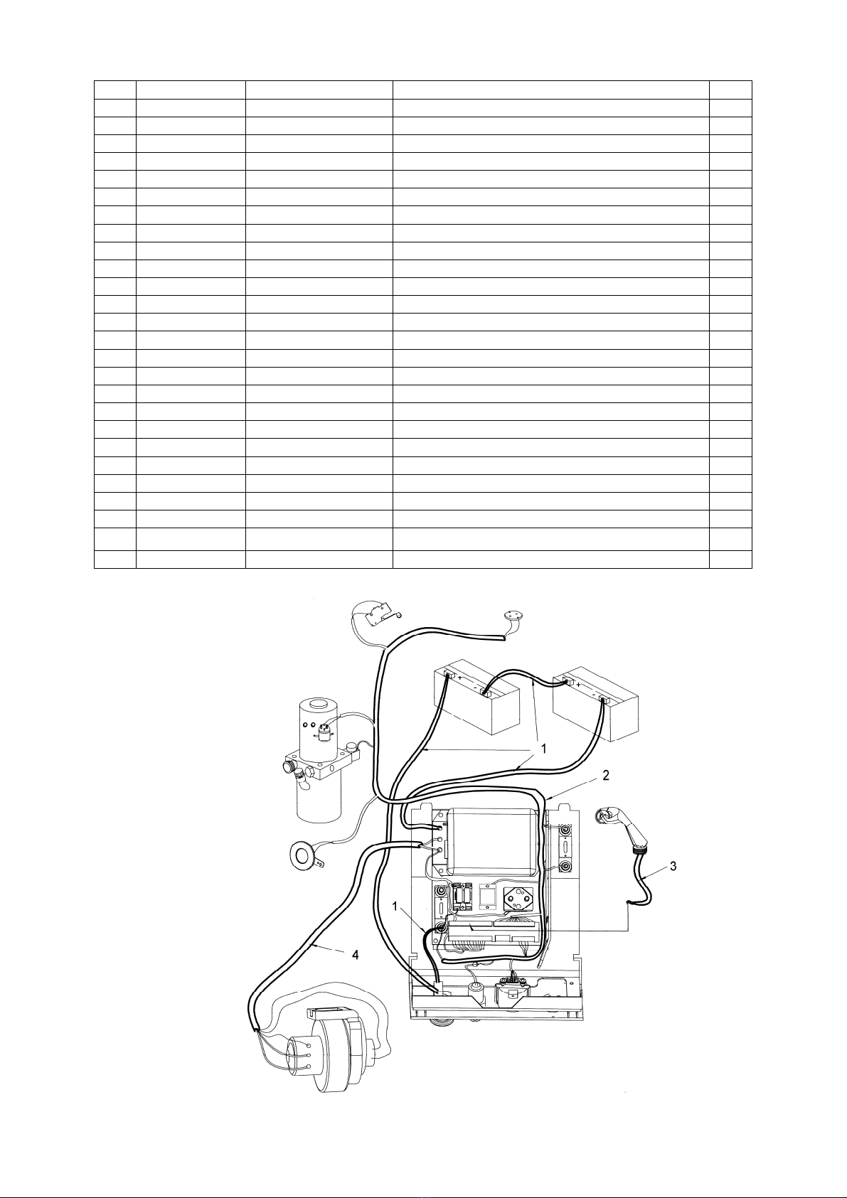
CABLE SYSTEM
17
No. Code NL. Drawing No. Description Qty.
1 1000433008 DQ-LPT15DC-X1 Battery cable 1
2
3 1000433011 DQ-LPT15DC-X4 Control cable 1
4 1000433017 DQ-LPT15DC-X10 Drive motor cable 1
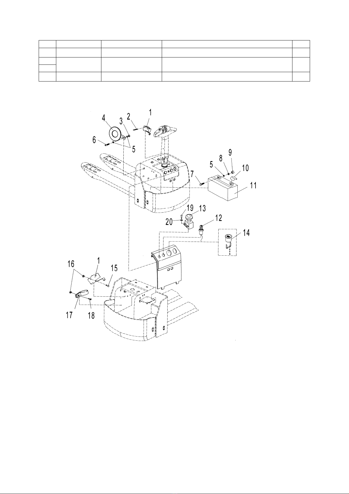
3.2 INSTALLATION OF ELECTRIC
1. Micro switch Z-15GW2 8 Washer 15. Screw
2. Screw 9 Nut 16. Nut
3. Nut 10. Rubber Cover 17. Clip
4. Horn DC24V 11. Battery – 12V/80Ah 18. Screw
5. Washer 12. Lock LKS-101A 19. Screw
6 Screw 13. Emergency button ZDK31-250 20. Washer
7 Screw 14. Battery Indicator CURTIS 803

18
3.3 DRIVE WHEEL
Type: 3EL-DC-0.75
Drive Motor
Model HS XQT-0.75-1DH1U
Rate voltage DC 24V
R.P.M 3200rpm
Rate output 1.0kw
Rate hour 60 min.
Rated current 45 A
Amperager rating- max 6.4A
Amperager rating- min 3.5A
Insulation class F class
Electromagnetic Brake
Model G027-REB0908X-R
Rate voltage DC 24V
Rate Power 27W
Output Torque 8 N·M
Gear Box
transmission ratio i=1:30
3.4 PUMP UNIT
Type: MR2-B-V1B-F4.5-PCMAV1Y-TK05C-F2
Item Specification
Rated voltage 24V
Rated output 0.8 kw
R.P.M 3000 rpm
Rated current 70 A
Rated hour 2 min.
Insulation class F class
IP Code IP54
Displacement 0.56cc/rec
Max. operating pressure 220bar
3.5 BATTERY
Rate Specification
Rated voltage 12V
Capacity (5 hours) 80Ah
Overall size (L*W*H) 260mm*168mm*226mm

19
25A DURATION OF DISCHARGING CURVE (ENVIRONMENTAL TEMPERATURE = 25OC)
100% DURATION OF DISCHARGING LIFE TEST CURVE ( ENVIRONMENTAL TEMPERATURE =
25OC)
CHARGING RATE
Table of contents
Other Noblift Truck manuals


 Operator's manual")


