Service Manual
Table of Contents
Service Manual
Table of Contents
Table of Contents
Part Ⅰ: Technical Information.......................................................................1
1. Summary......................................................................................................................1
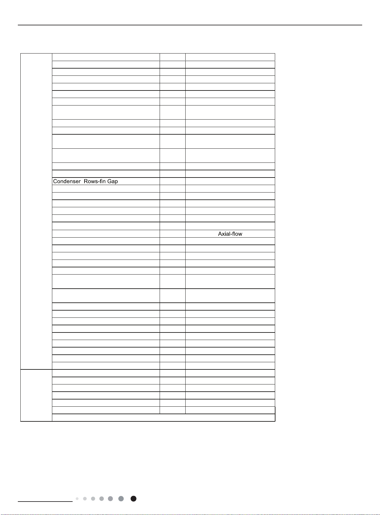
..........................................................................................................2
...........................................................................................................3
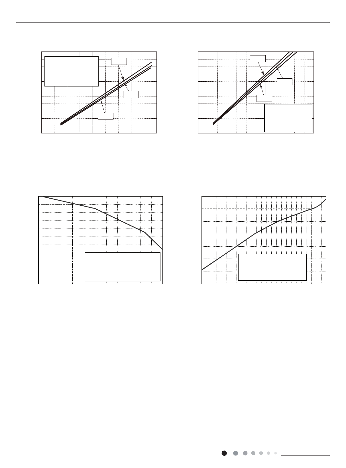
2.2 Operation Characteristic Curve ........................................................................................6
2.3 Capacity Variation Ratio According to Temperature ....................................................... ..6
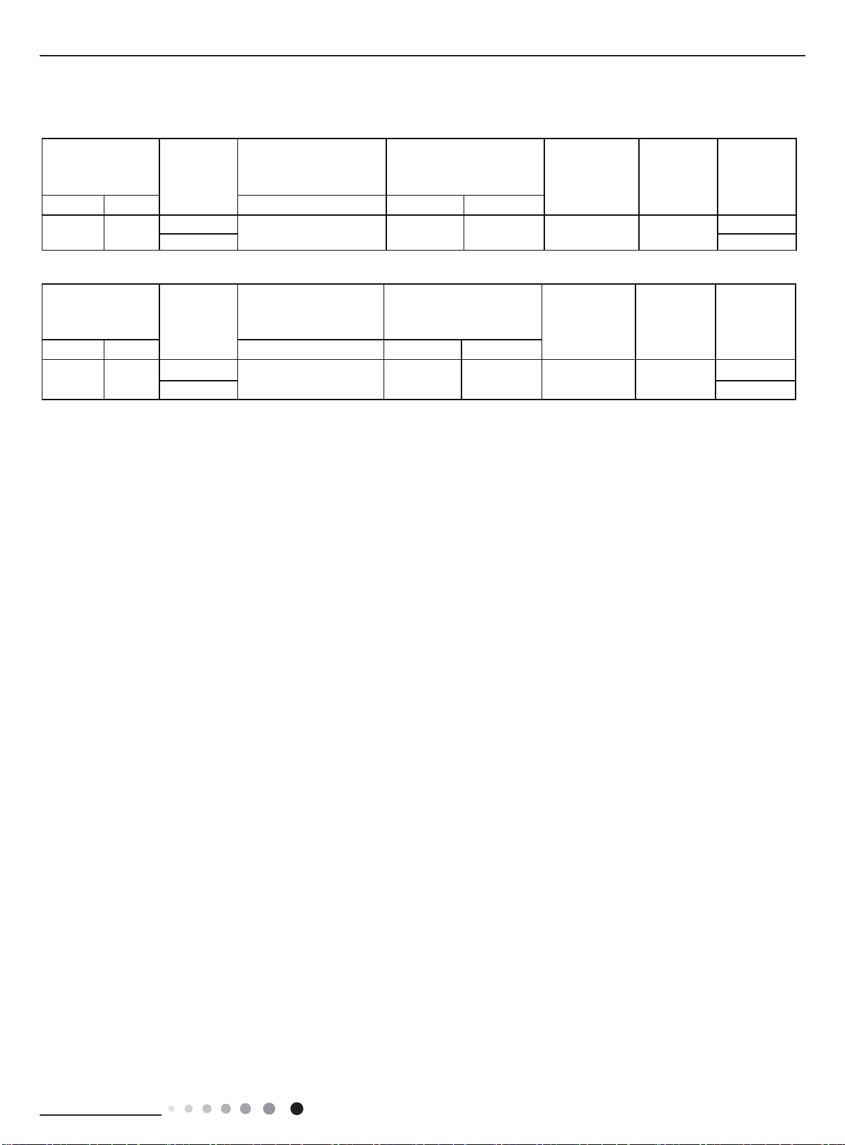
2.4 Cooling and Heating Data Sheet in Rated Frequency .....................................................7
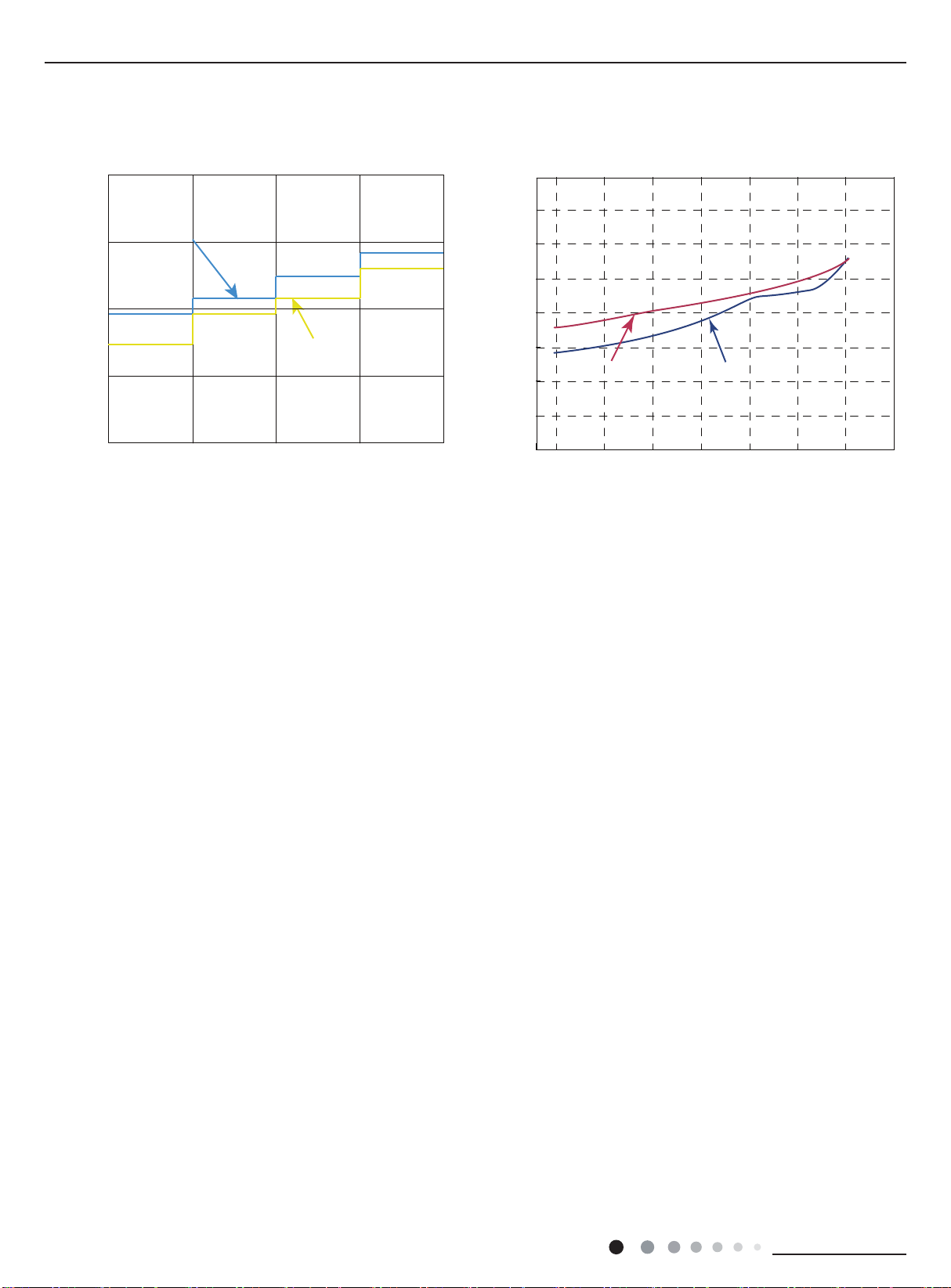
2.5 Noise Curve......................................................................................................................8
3. Outline Dimension Diagram.........................................................................................9
3.1 Indoor Unit........................................................................................................................9
3.2 Outdoor Unit ...................................................................................................................10
4. Refrigerant System Diagram....................................................................11
5. Electrical Part.........................................................................................................12
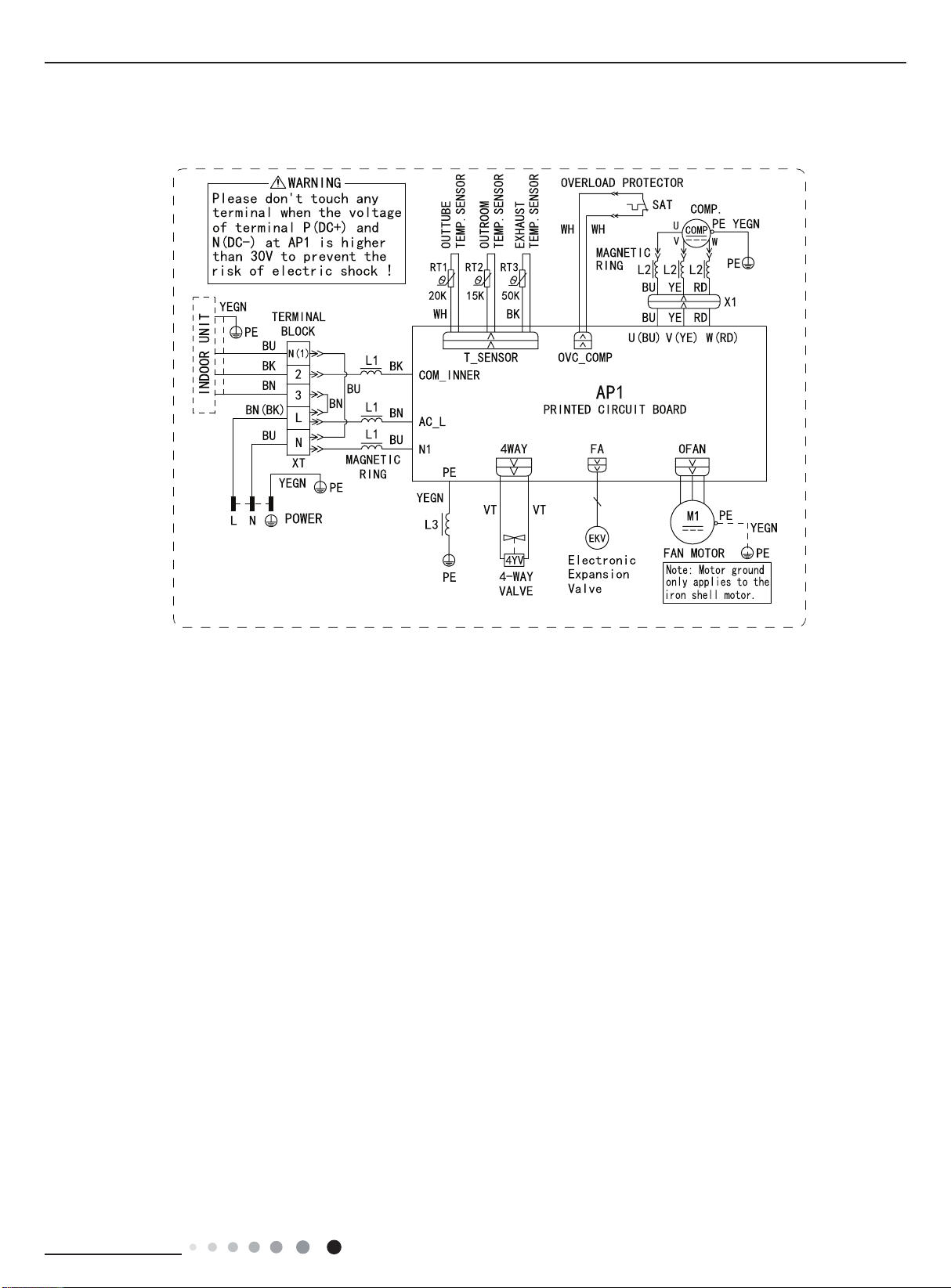
5.1 Wiring Diagram...............................................................................................................12
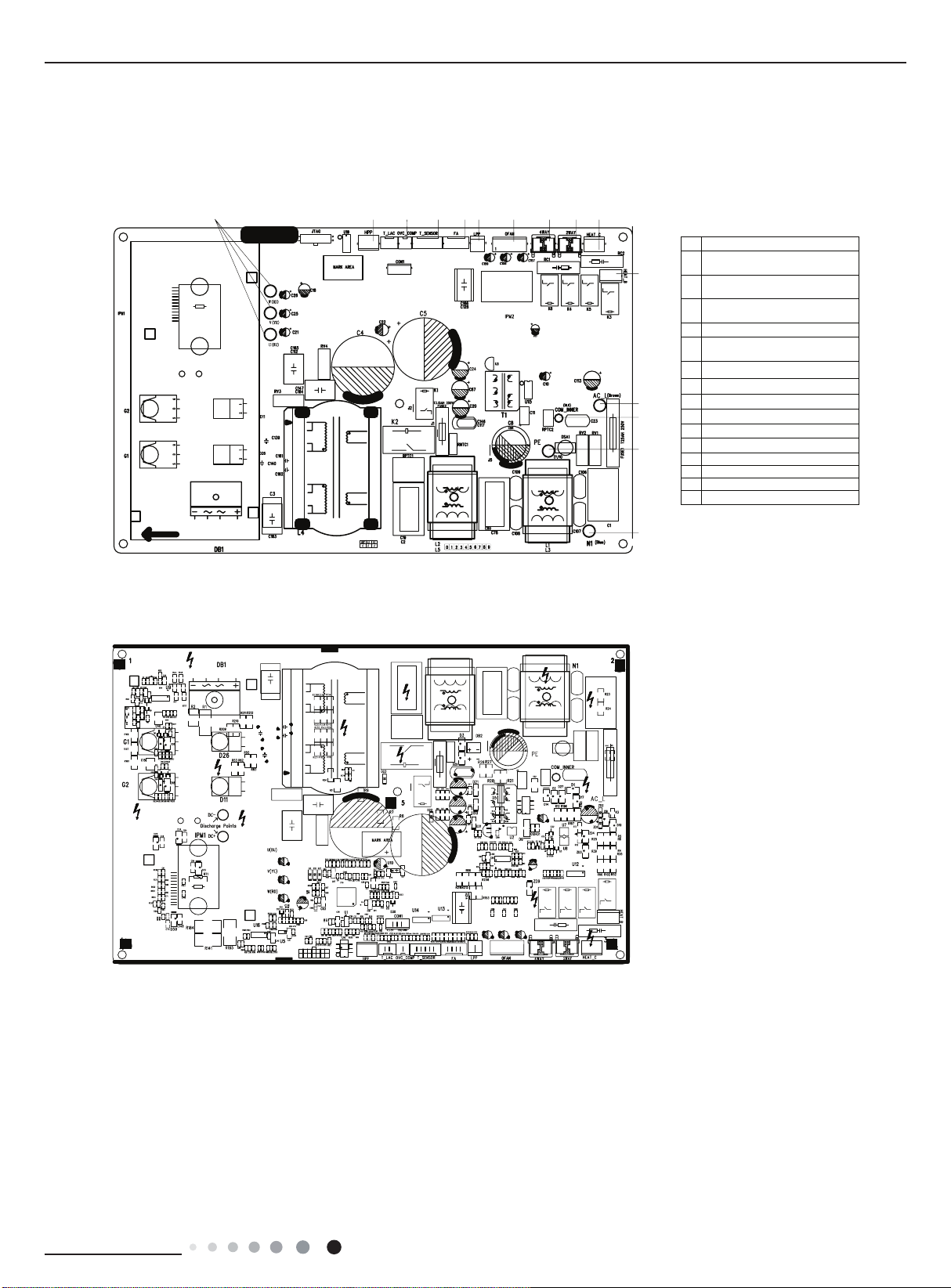
5.2 PCB Printed Diagram .....................................................................................................14
6. Function and Control......................................................................................16
6.1 Remote Controller Introduction.......................................................................................16
6.2 Preparation before operation..........................................................................................16
6.3 Introduction of operation function....................................................................................16
6.4 Introduction of special functions......................................................................................18
6.4 Brief Description of Modes and Functions......................................................................20
Part Ⅱ: Installation and Maintenance .................................................29
7. Notes for Installation and Maintenance..........................................29
8. Installation................................................................................................................33
8.1 Installation Dimension Diagram......................................................................................33
8.2 Installation Parts-checking ............................................................................................35
8.3 Selection of Installation Location....................................................................................35
8.4 Requirements for electric connection .............................................................................35
8.5 Installation of Indoor Unit................................................................................................35
8.6 Installation of Outdoor unit .............................................................................................38
8.7 Vacuum Pumping and Leak Detection ...........................................................................39
8.8 Check after Installation and Test operation ....................................................................39