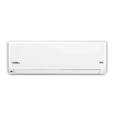
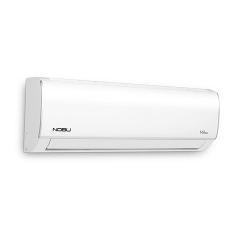
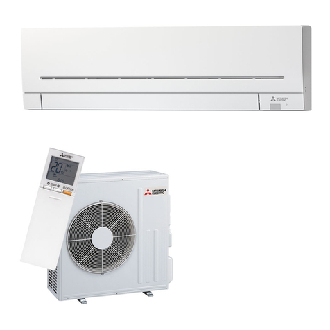
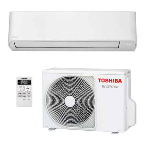
Nobu NBL4-09IDU32 User manual

Wall Mounted Air-Conditioning Unit
English
NBL4-09IDU32 / NBL4-09ΟDU32
NBL4-12IDU32 / NBL4-12ΟDU32
MODELS
Wall Mounted Air-Conditioning Unit
Service Manual
Wall Mounted Air-Conditioning Unit

Service Manual

Service Manual
Table of Contents
Service Manual
Table of Contents
Part Ⅰ: Technical Information.......................................................................1
1. Summary......................................................................................................................1
..........................................................................................................2
...........................................................................................................2
2.2 Operation Characteristic Curve ........................................................................................6
2.3 Capacity Variation Ratio According to Temperature ....................................................... ..6
2.4 Cooling and Heating Data Sheet in Rated Frequency .....................................................7
2.5 Noise Curve......................................................................................................................7
3. Outline Dimension Diagram........................................................................8
3.1 Indoor Unit........................................................................................................................8
3.2 Outdoor Unit .....................................................................................................................9
4. Refrigerant System Diagram....................................................................10
5. Electrical Part.........................................................................................................11
5.1 Wiring Diagram...............................................................................................................11
5.2 PCB Printed Diagram .....................................................................................................13
6. Function and Control......................................................................................15
6.1 Remote Controller Introduction .....................................................................................15
6.2 Preparation before operation..........................................................................................15
6.3 Introduction of operation function ..................................................................................15
6.4 Introduction of special functions ....................................................................................17
6.5 Brief Description of Modes and Functions......................................................................19
Part Ⅱ: Installation and Maintenance .................................................24
7. Notes for Installation and Maintenance..........................................24
8. Installation................................................................................................................28
8.1 Installation Dimension Diagram......................................................................................28
8.2 Installation Parts-checking ............................................................................................30
8.3 Selection of Installation Location....................................................................................30
8.4 Requirements for electric connection .............................................................................30
8.5 Installation of Indoor Unit................................................................................................30
8.6 Installation of Outdoor Unit.............................................................................................33
8.7 Vacuum Pumping and Leak Detection ...........................................................................34
8.8 Check after Installation and Test Operation ...................................................................34
Table of Contents

Service Manual
Table of contents
Service Manual
9. Maintenance............................................................................................................74
9.1 Error Code List ...............................................................................................................74
9.2 Procedure of Troubleshooting ........................................................................................82
9.3 Troubleshooting for Normal Malfunction.........................................................................97
10. Exploded View and Parts List ..............................................................99
10.1 Indoor Unit....................................................................................................................99
10.2 Outdoor Unit ...............................................................................................................109
11. Removal Procedure.....................................................................................116
11.1 Removal Procedure of Indoor Unit .............................................................................116
11.2 Removal Procedure of Outdoor Unit ..........................................................................126
Appendix:......................................................................................................................141
Appendix 1: Reference Sheet of Celsius and Fahrenheit ..................................................141
Appendix 2: Conguration of Connection Pipe...................................................................141
Appendix 3: Pipe Expanding Method .................................................................................142
Appendix 4: List of Resistance for Temperature Sensor ....................................................143
Table of Contents

Technical Information 1
Service Manual
1
Technical Information
Service Manual
Part Ⅰ: Technical Information
1. Summary
Indoor Unit
NBL4-09IDU32, NBL4-12IDU32
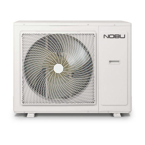
Outdoor Unit
NBL4-09ΟDU32 NBL4-12ΟDU32
Remote Controller

Technical Information
2
Service Manual
3
Technical Information
Service Manual
Parameter Unit Value
Model NBL4-09IDU32
Power
Supply
Rated Voltage V~ 220-240
Rated Frequency Hz 50
Phases 1
Power Supply Mode Outdoor
Cooling Capacity(Min~Max) W 2600(500~3350)
Heating Capacity(Min~Max) W 2800(500~3500)
Cooling Power Input(Min~Max) W 805(160~1400)
Heating Power Input(Min~Max) W 755(200~1500)
Cooling Current Input A 3.9
Heating Current Input A 3.4
Rated Input W 1500
Rated Current A 6.3
Air Flow Volume(SH/H/M//L/SL) m3/h 560/490/430/330/-
Dehumidifying Volume L/h 0.8
EER W/W 3.23
COP W/W 3.71
SEER W/W 6.1
SCOP(Average/Warmer/Colder) W/W 4.0/5.1/3.2
Application Area m212-18
Indoor
Unit
Indoor Unit Model NBL4-09IDU32
Fan Type
Fan Diameter Length(DXL) mm Ф98X580
Cooling Speed(SH/H/M//L/SL) r/min 1300/1200/1050/800/-
Heating Speed(SH/H/M//L/SL) r/min 1300/1200/1050/900/-
Fan Motor Power Output W 20
Fan Motor RLA A 0.215
Fan Motor Capacitor μF 1
Evaporator Form Aluminum Fin-copper Tube
Evaporator Pipe Diameter mm Ф5
mm 2-1.4
Evaporator Coil Length (LXDXW) mm 584X22.8X266.7
Swing Motor Model MP24AA
Swing Motor Power Output W 1.5
Fuse Current A 3.15
Sound Pressure Level(SH/H/M//L/
SL) dB (A) 39/36/32/28/-
Sound Power Level(SH/H/M//L/SL) dB (A) 55/52/44/38/-
Dimension (WXHXD) mm 790X275X200
Dimension of Carton Box (LXWXH) mm 863X268X352
Dimension of Package(LXWXH) mm 866X271X367
Net Weight kg 9
Gross Weight kg 11

Technical Information 3
Service Manual
4Technical Information
Service Manual
The above data is subject to change without notice. Please refer to the nameplate of the unit.
Outdoor
Unit
Outdoor Unit Model NBL4-12IDU32
Compressor Model QXF-B096zE190A
Compressor Oil FW68DA
Compressor Type Rotary
Compressor LRA. A 20.00
Compressor RLA A 4.21
Compressor Power Input W 943
Compressor Overload Protector 1NT11L-6233 HPC115/95U1
KSD115ºC
Throttling Method Capillary
Set Temperature Range ºC 16~30
Cooling Operation Ambient Temperature
Range ºC -15~43
Heating Operation Ambient Temperature
Range ºC -15~24
Condenser Form Aluminum Fin-copper Tube
Condenser Pipe Diameter mm Φ7
mm 1-1.4
Condenser Coil Length (LXDXW) mm 710X19.05X508
Fan Motor Speed rpm 900
Fan Motor Power Output W 30
Fan Motor RLA A 0.36
Fan Motor Capacitor μF /
Outdoor Unit Air Flow Volume m3/h 1600
Fan Type
Fan Diameter mm Φ400
Defrosting Method Automatic Defrosting
Climate Type T1
Isolation I
Moisture Protection IPX4
Permissible Excessive Operating
Pressure for the Discharge Side MPa 4.3
Permissible Excessive Operating
Pressure for the Suction Side MPa 2.5
Sound Pressure Level (H/M/L) dB (A) 52/-/-
Sound Power Level (H/M/L) dB (A) 61/-/-
Dimension(WXHXD) mm 782X540X320
Dimension of Carton Box (LXWXH) mm 820X355X580
Dimension of Package(LXWXH) mm 823X358X595
Net Weight kg 29.5
Gross Weight kg 32
Refrigerant R32
Refrigerant Charge kg 0.6
Connection
Pipe
Connection Pipe Length m 5
Connection Pipe Gas Additional Charge g/m 20
Outer Diameter Liquid Pipe mm Φ6
Outer Diameter Gas Pipe mm Φ9.52
Max Distance Height m 10
Max Distance Length m 19
Note: The connection pipe applies metric diameter.
3
Technical Information
Service Manual
Parameter Unit Value
Model L4VI32-09WiFiR
Power
Supply
Rated Voltage V~ 220-240
Rated Frequency Hz 50
Phases 1
Power Supply Mode Outdoor
Cooling Capacity(Min~Max) W 2600(500~3350)
Heating Capacity(Min~Max) W 2800(500~3500)
Cooling Power Input(Min~Max) W 805(160~1400)
Heating Power Input(Min~Max) W 755(200~1500)
Cooling Current Input A 3.9
Heating Current Input A 3.4
Rated Input W 1500
Rated Current A 6.3
Air Flow Volume(SH/H/M//L/SL) m3/h 560/490/430/330/-
Dehumidifying Volume L/h 0.8
EER W/W 3.23
COP W/W 3.71
SEER W/W 6.1
SCOP(Average/Warmer/Colder) W/W 4.0/5.1/3.2
Application Area m212-18
Indoor
Unit
Indoor Unit Model L4VI32-09
Fan Type
Fan Diameter Length(DXL) mm Ф98X580
Cooling Speed(SH/H/M//L/SL) r/min 1300/1200/1050/800/-
Heating Speed(SH/H/M//L/SL) r/min 1300/1200/1050/900/-
Fan Motor Power Output W 20
Fan Motor RLA A 0.215
Fan Motor Capacitor μF 1
Evaporator Form Aluminum Fin-copper Tube
Evaporator Pipe Diameter mm Ф5
mm 2-1.4
Evaporator Coil Length (LXDXW) mm 584X22.8X266.7
Swing Motor Model MP24AA
Swing Motor Power Output W 1.5
Fuse Current A 3.15
Sound Pressure Level(SH/H/M//L/
SL) dB (A) 39/36/32/28/-
Sound Power Level(SH/H/M//L/SL) dB (A) 55/52/44/38/-
Dimension (WXHXD) mm 790X275X200
Dimension of Carton Box (LXWXH) mm 863X268X352
Dimension of Package(LXWXH) mm 866X271X367
Net Weight kg 9
Gross Weight kg 11

Technical Information
4
Service Manual
5
Technical Information
Service Manual
Parameter Unit Value
Model NBL4-12IDU32
Power
Supply
Rated Voltage V~ 220-240
Rated Frequency Hz 50
Phases 1
Power Supply Mode Outdoor
Cooling Capacity(Min~Max) W 3500(800~3700)
Heating Capacity(Min~Max) W 3670(900~380)
Cooling Power Input(Min~Max) W 1085(220~1400)
Heating Power Input(Min~Max) W 990(220~1500)
Cooling Current Input A 5.0
Heating Current Input A 4.5
Rated Input W 1500
Rated Current A 7.2
Air Flow Volume(SH/H/M//L/SL) m3/h 680/590/490/420/-
Dehumidifying Volume L/h 1.4
EER W/W 3.26
COP W/W 3.71
SEER W/W 6.1
SCOP(Average/Warmer/Colder) W/W 4.0/5.1/3.4
Application Area m216-24
Indoor
Unit
Indoor Unit Model NBL4-12IDU32
Fan Type
Fan Diameter Length(DXL) mm Φ98X633.5
Cooling Speed(SH/H/M//L/SL) r/min 1350/1200/1050/850/-
Heating Speed(SH/H/M//L/SL) r/min 1300/1150/1000/900/-
Fan Motor Power Output W 20
Fan Motor RLA A 0.31
Fan Motor Capacitor μF 1.5
Evaporator Form Aluminum Fin-copper Tube
Evaporator Pipe Diameter mm Ф5
mm 2-1.5
Evaporator Coil Length (LXDXW) mm 635X22.8X306.3
Swing Motor Model MP24BA
Swing Motor Power Output W 2
Fuse Current A 3.15
Sound Pressure Level(SH/H/M//L/SL) dB (A) 42/38/34/31/-
Sound Power Level(SH/H/M//L/SL) dB (A) 56/52/48/45/-
Dimension (WXHXD) mm 845X289X209
Dimension of Carton Box (LXWXH) mm 918X278X364
Dimension of Package(LXWXH) mm 921X281X379
Net Weight kg 10.5
Gross Weight kg 12.5

Technical Information 5
Service Manual
6Technical Information
Service Manual
The above data is subject to change without notice. Please refer to the nameplate of the unit.
Outdoor
Unit
Outdoor Unit Model NBL4-12ΟDU32
Compressor Model QXF-B096zE190A
Compressor Oil FW68DA
Compressor Type Rotary
Compressor LRA. A 20
Compressor RLA A 4.21
Compressor Power Input W 943
Compressor Overload Protector 1NT11L-6233 HPC115/95U1 KSD115ºC
Throttling Method Capillary
Set Temperature Range ºC 16~30
Cooling Operation Ambient Temperature
Range ºC -15~43
Heating Operation Ambient Temperature
Range ºC -15~24
Condenser Form Aluminum Fin-copper Tube
Condenser Pipe Diameter mm Φ7.94
mm 1-1.4
Condenser Coil Length (LXDXW) mm 731X19.05X550
Fan Motor Speed rpm 900
Fan Motor Power Output W 30
Fan Motor RLA A 0.36
Fan Motor Capacitor μF /
Outdoor Unit Air Flow Volume m3/h 2200
Fan Type
Fan Diameter mm Φ438
Defrosting Method Automatic Defrosting
Climate Type T1
Isolation I
Moisture Protection IPX4
Permissible Excessive Operating
Pressure for the Discharge Side MPa 4.3
Permissible Excessive Operating
Pressure for the Suction Side MPa 2.5
Sound Pressure Level (H/M/L) dB (A) 53/-/-
Sound Power Level (H/M/L) dB (A) 62/-/-
Dimension(WXHXD) mm 848X596X320
Dimension of Carton Box (LXWXH) mm 878X360X630
Dimension of Package(LXWXH) mm 881X363X645
Net Weight kg 31
Gross Weight kg 34
Refrigerant R32
Refrigerant Charge kg 0.7
Connection
Pipe
Connection Pipe Length m 5
Connection Pipe Gas Additional Charge g/m 20
Outer Diameter Liquid Pipe mm Φ6
Outer Diameter Gas Pipe mm Φ9.52
Max Distance Height m 10
Max Distance Length m 20
Note: The connection pipe applies metric diameter.

Technical Information
6
Service Manual
11
Technical Information
Service Manual
2.2 Operation Characteristic Curve
2.3 Capacity Variation Ratio According to Temperature
gnitaeHgnilooC
50
60
70
80
90
100
110
120
130
32 33 34 35 36 37 38 39 40 41 42 43 44 45 46
Capacity ratio(%)
Outdoor temp. (°C)
Capacity ratio(
%)
–15 –10 –5
110
100
90
80
70
60
50
40
0 5 7 10
Conditions
Indoor:DB20°C
Indoor air flow:Super High
Pipe length:5m
Outdoor temp.(°C)
Condition
Indoor:DB27°C WB19°C
Indoor air flow:
High
Pipe length:5m
Heating operation ambient temperature range is -15ºC~24ºC
0 10 20 30 40 50 60 70 90 0 10 20 30 40 50 60 70 80 90 100
120
110
80
11
10
9
8
7
6
5
4
3
2
1
0
Compressor speed (rps)
)A(tnerruC
11
10
9
8
7
6
5
4
3
2
1
0
Compressor speed (rps)
)A(tnerruC
220V
230V
240V
220V
230V
240V
Conditions
Indoor: DB27°C/WB19°C
Outdoor: DB35°C/WB24°C
Indoor air flow: High
Pipe length: 5m
Conditions
Indoor: DB20°C/WB15°C
Outdoor: DB7°C/WB6°C
Indoor air flow: High
Pipe length: 5m
Cooling Heating

Technical Information 7
Service Manual
12 Technical Information
Service Manual
2.4 Cooling and Heating Data Sheet in Rated Frequency
2.5 Noise Curve
Indoor side noise when blowing Outdoor side noise when blowing
Indoor fan motor rotating speed Compressor frequency(Hz)
Noise/dB(A)
50
60
30
40
20
Low Middle High Super High
12K
09K
40
42
44
46
48
50
52
54
56
20 4030 50 60 70 80
90
Noise dB(A)
09&12K Cooling
09&12K Heating
Cooling:
Rated cooling
condition(°C) (DB/WB) Model
Pressure of gas pipe
connecting indoor and
outdoor unit
Inlet and outlet pipe
temperature of heat
exchanger
Fan speed of
indoor unit
Fan speed of
outdoor unit
Compressor
revolution
(rps)
Indoor Outdoor P (MPa) T1 (°C) T2 (°C)
27/19 35/24 09K 0.8 ~ 1.1 12 to 15 65 to 38 TURBO High 49
12K 11 to 14 64 to 37 60
27/19 35/24 18K 0.9 ~ 1.1 12 to 14 75 to 37 Super High High 52
Instruction:
T1: Inlet and outlet pipe temperature of evaporator
T2: Inlet and outlet pipe temperature of condenser
P: Pressure at the side of big valve
Connection pipe length: 5 m.
Heating:
Rated cooling
condition(°C) (DB/WB) Model
Pressure of gas pipe
connecting indoor and
outdoor unit
Inlet and outlet pipe
temperature of heat
exchanger
Fan speed of
indoor unit
Fan speed of
outdoor unit
Compressor
revolution
(rps)
Indoor Outdoor P (MPa) T1 (°C) T2 (°C)
20/- 7/6 09K 2.8 ~ 3.2 35 to 63 2 to 5 TURBO High 59
12K 35 to 65 2 to 5 67
20/- 7/6 18K 2.2 ~ 2.4 70 to35 2 to 4 Super High High 65
09/12K

Technical Information
8
Service Manual
14 Technical Information
Service Manual
3. Outline Dimension Diagram
3.1 Indoor Unit
Unit:mm
Model W H D
09K 790 275 200
12K 845 289 209
W
12K
09K
D
H
90
150
54
168.5 462 159.5
Φ55Φ55
54
123.5 542 179.5
83.2
124.7
35
Φ55Φ55
35

Technical Information 9
Service Manual
15
Technical Information
Service Manual
3.2 Outdoor Unit
712
782
257
320
540
286
510
Unit:mm
257
780
596
842
286
540
320
Unit:mm
NBL4-09ΟDU32
NBL4-12ΟDU32

Technical Information
10
Service Manual
17
Technical Information
Service Manual
Indoor unit Outdoor unit
COOLING
HEATING
4-Way valve
Discharge
Suction
Heat
exchanger
(evaporator) Heat
exchanger
(condenser)
Valve
Valve
Liquid pipe
side
Gas pipe
side
Strainer Strainer
Capillary
Accumlator
Compressor
4. Refrigerant System Diagram
Liquid pipe:1/4" (6mm)
Gas pipe:3/8" (9.52mm)
09/12K

Technical Information 11
Service Manual
18 Technical Information
Service Manual
5. Electrical Part
5.1 Wiring Diagram
●Instruction
Symbol Symbol Color Symbol Symbol Color Symbol Name
WH White GN Green CAP Jumper cap
YE Yellow BN Brown COMP Compressor
RD Red BU Blue Grounding wire
YEGN Yellow/Green BK Black / /
VT Violet OG Orange / /
Note: Jumper cap is used to determine fan speed and the swing angle of horizontal lover for this model.
600007000688
●Indoor Unit
NBL4-09IDU32, NBL4-12IDU32

Technical Information
12
Service Manual
21
Technical Information
Service Manual
600007000687
● Outdoor Unit
NBL4-09ΟDU32
NBL4-12ΟDU32
600007000763

Technical Information 13
Service Manual
24 Technical Information
Service Manual
No Name
1Interface of communication wire for
indoor unit and outdoor unit
2Interface of live wire
3Interface of health function neutral
wire
4Interface of neutral wire
5 Interface of fan
6Interface of health function live wire
7Jumper cap
8Auto button
9 Up&down swing interface
10 Feedback interface of indoor unit
11 left&right swing interface
12 Interface of wi
13 Interface of tube temperature sensor
14 Wired controller
15 Display interface
16 Fuse
17 Terminal for gate control function
5.2 PCB Printed Diagram
Indoor Unit
●Top view
●Bottom view
1
2
16
3 4 5 6 78 9 10
11
12
13
14
15
17

Technical Information
14
Service Manual
25
Technical Information
Service Manual
●Top view
●Bottom view
1
2
3 4
5
6
7
8
9
10111213
Outdoor Unit
No. Name
1 Compressor wiring terminal
2 Reactor wiring terminal
3Outdoor fan wiring terminal
4Terminal of chassis electric
heater
5Terminal of compressor
electric heater
6Terminal of 4-way valve
7Grounding wire
8Communication wire
9Neutral wire
10 Live wire
11 Terminal of electronic
expansion valve
12 Terminal of temperature
sensor
13 Compressor overload terminal
09/12K

Technical Information 15
Service Manual
27
Technical Information
Service Manual
6. Function and Control
6.1 Remote Controller Introduction
No. Button name Function
1 ON/OFF Turn on or turn off the unit
2 TURBO Set turbo function
3 MODE Set operation mode
4 Set up&down swing status
5 I FEEL Set I FEEL function
6 TEMP Switch temperature displaying type on the unit’s display
7 Set health function and air function
8 LIGHT Set light function
9 X-FAN Set X-FAN function
10 SLEEP Set sleep function
11 CLOCK Set clock of the system
12 TOFF Set timer off function
13 TON Set timer on function
14 Set left&right swing status
15 FAN Set fan speed
16 / Set temperature and time
6.2 Preparation before operation
When using the remote controller for the first time or after replacing the batteries,
please set the time of the system according to current time in the following steps:
(1). Pressing CLOCK button, is blinking.
(2). Pressing or button, the clock time will increase or decrease rapidly.
(3). Press CLOCK button again to confirm the time and return to display current time.
6.3 Introduction of operation function
(1). Selecting operation mode
In unit on status, press MODE button to select operation mode in following sequence:
(2). Setting temperature
In unit on status, press button to increase setting temperature and press button to decrease setting temperature. The
Note: Under auto mode, manual adjustment of temperature is not needed.
range of temperature is from 16ºC to 30ºC.
(3). Adjusting fan speed
In unit on status, press FAN button to adjust fan speed in following sequence:
Notes:
①.When operation mode changes, fan speed is memoried;
②.Under dry mode, fan speed is low and can not be adjusted.
(4). Setting swing function
Setting left&right swing
1). Under simple swing status, press button to adjust left&right swing status;

Technical Information
16
Service Manual
28 Technical Information
Service Manual
2). Under fixed-angle swing status, press button to adjust left&right swing angle circularly as below:
Note: operate continuously left&right swing in 2 seconds, swing states will change
according to above-mentioned order, or switch closed state and state.
Setting up&down swing
1). Under simple swing status, press button to adjust up&down swing status;
2). Under fixed-angle swing status, press button to adjust up&down swing angle circularly as below:
Note: operate continuously left&right swing in 2 seconds, swing states will change according to above-mentioned order, or switch
closed state and state
(5). Setting turbo function
Under cool or heat mode, press TURBO button to set turbo function.
When is displayed, turbo function is on.
When is not displayed, turbo function is off.
When turbo function is on, the unit operates in super high speed to achieve quick cooling or heating. When turbo function is off,
the unit operates in setting fan speed.
(6). Setting light function
The light on the receiver light board will display present operation status. If you want to turn
off the light, please press LIGHT button. Press this button again to turn on the light.
(7). Viewing ambient temperature
In unit on status, receiver light board or wired controller is defaulted to display setting
temperature. Press TEMP button to view indoor or outdoor ambient temperature.
When is displayed, it means the displayed temperature is setting temperature.
When is displayed, it means the displayed temperature is indoor ambient temperature.
When is displayed, it means the displayed temperature is outdoor ambient temperature.
Note: setting temperature is always displayed in Remote Controller.
(8). Setting X-FAN function
In cool or dry mode, press X-FAN button to set X-FAN function.
When is displayed, X-FAN function is on.
When is not displayed, X-FAN function is off.
When X-FAN function is on, the water on the evaporator will be blown away until turning off the unit to avoid mildew.
(9). Setting health function
In unit on status, press button to set health function.
When is displayed, health function is on.
When is not displayed, health function is off.
Health function is available when the unit is equipped with anion generator. When health function is on, the anion generator will start
operation, adsorbing the dusts and killing the bacteria in the room.
(10). Setting air function
Press button until is displayed, then air function is turned on.
Press button until is disappeared, then air function is turned off.
When the indoor unit is connected with fresh air valve, air function setting can control the connection of fresh air valve, which can
control the fresh air volume and improve the air quality inside the room.
This manual suits for next models
3
Table of contents
Other Nobu Air Conditioner manuals

Nobu
Nobu NBO3-09IDU User manual

Nobu
Nobu NBO3-12IDU User manual

Nobu
Nobu NBO-12IDU User manual

Nobu
Nobu NBL4-18IDU32 User manual

Nobu
Nobu NBL4-12IDU32 User manual

Nobu
Nobu NBFS-48IDU User manual

Nobu
Nobu NBO-09IDU User manual

Nobu
Nobu NBFS-48IDU User manual

Nobu
Nobu OSK103 User manual

Nobu
Nobu NBFS-48IDU User manual