NODEXON NX-5610-24F4G User manual

NX-5610-24F4G
Core Aggregation Switch
Product Guide

1
Statement of Copyright
Nodexon Networks©2021
All copyrights in this document are reserved by Nodexon Networks. Without Nodexon Networks'
prior written approval, any reproduction, excerption, backup, modification, transmission,
translation, or commercial use of this document or any portion of this document, in any form or
by any means, is forbidden.
Statement of Exemption
This material is being distributed "as is." This document's contents are subject to change at any
time without notice. Please visit the Nodexon Networks website for the most up-to-date
information. Nodexon Networks makes every effort to guarantee content accuracy, but cannot be
held liable for any losses or damages incurred as a result of content omissions, inaccuracies, or
mistakes.

2
Preface
Thank you for using our products. This manual will guide you through the installation of the
device.
This manual describes the functional and physical features and provides the device installation
steps, hardware troubleshooting, module technical specifications, and specifications and usage
guidelines for cables and connectors.
Audience
It is intended for the users who have some experience in installing and maintaining network
hardware. At the same time, it is assumed that the users are already familiar with the related
terms and concepts.
Obtaining Technical Assistance
Website:https://www.nodexon.com/
Technical Support Website:https://nodexon.com/support
Community:http://www.nodexon.com/community
Case Portal :https://www.nodexon.com/caseportal
Website:https://www.nodexon.com/

3
"Product Use Guide"
Introduces NX-5610-24F4G switch software and hardware parameters, installation methods
and matters need attention during the installation process matters.
This manual includes the following sections:
Chapter 1 : Product introduction. Briefly describe the basic functions and features of the
switch, detailed hardware and software specifications, and appearance information.
Chapter 2 : Hardware Connections. Guide the connection and precautions between the switch
and other devices.
Chapter 3 : Product Installation. Guide the hardware installation method and precautions of
the switch.
Chapter 4: Product Packaging and Use Recommendations

4
Chapter 1 Product Introduction
1.1 Product Brief Introduction
The NX-5610-24F4G uses a new generation of high-performance hardware and software
platforms to provide flexible, cost-effective full Gigabit access and uplink ports, support for
Layer 3 routing protocols, complete security protection mechanisms, and comprehensive
ACL/QoS policies. Rich VLAN function, easy to manage and maintain, meets the user's easy-to-
manage, high-security, and low-cost networking requirements for network devices. It is suitable
for network access, aggregation, and core application scenarios in campus, hotel, and enterprise
campus.
1.2 product characteristics
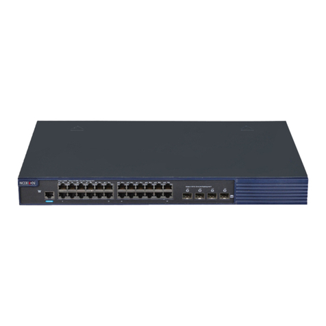
•Full Gigabit Ethernet port: 24 full Gigabit RJ45 network port, and. 4 X 10G SFP fiber
interface,4 Gigabit RJ45 port(Combo), breaking the traditional fast limitation, data
transmission without blunt
•Broadcom high- end chips, can greatly enhance the network data processing rate
•Support DHCP server, DHCP relay, DHCP Snooping
•Support one-stop management of Apollo cloud platform: Support cloud platform to
visualize management of resources on switches and PD devices, making operation and
maintenance management easier
1.3 Product Software and Hardware Specifications
Hardware specification
Chip
Broadcom high performance chip
Flash
16MB
RAM
256 MB DDR

5
port
24 10/100/1000Mbps RJ45
ports
4 10G SFP+ fiber ports
4 1000Mbps RJ45 port(Combo)
1 RJ45 Console port, 1 1000M
RJ45 management port
1 USB 2.0, 1 Mini-usb Console port
performance
Forward mode: store and forward
Backplane bandwidth: 128 Gbps
Packet forwarding rate: 95.2 Mpps
Support 16 K MAC address table depth
Lightning
protection
± 6 KV
ESD
Contact: ±6K V air: ±8K V
Input power
100-240V/50-60Hz

6
Dimensions (L ×
W × H)
440mm × 320 mm × 44mm
Software features
routing
Support RIP V1/V2 ,
OSPFv1/OSPFv2 dynamic routing
Support static routing
DHCP
Support DHCP server
Support DHCP relay
Support DHCP Snooping
Support 4K VLANs
VLAN
Support 802.1Q VLAN, MAC VLAN, IP
VLAN
Voice VLAN
MAC address
table
Follow the IEEE 802.1d standard
Support MAC address automatic learning and aging

7
Support static, dynamic, filtering address table
Safety
features
Password protection
Support user access based on port number, IP address, and MAC address
Support HTTPS, SSL V3, TLS V1, SSH
V1/V2
Support IP-MAC-PORT ternary binding
Support ARP protection, IP source
protection, DoS protection
Support DHCP Snooping and DHCP
attack protection
Support 802.1X authentication, AAA
Support port security, port isolation

8
Support CPU protection
Access control
(ACL)
Support L2 (Layer 2) ~ L4 (Layer 4)
packet filtering
Support port mirroring, port redirection, flow rate limiting, QoS re-
marking
Quality of
Service (QoS)
Support 8 port queues
Support port priority, 802.1P priority,
DSCP priority
Support SP, WRR, W FQ priority scheduling algorithm
Spanning tree
Supports STP (IEEE 802.1d), RSTP (IEEE 802.1w) and MSTP (IEEE 802.1s)
protocols
Support loop protection, root bridge protection, TC protection, BPDU
protection, BPDU filtering

9
Multicast
Support IGMP v1/v2 Snooping
Support fast leave mechanism
Support for multicast VLAN
Supports multicast filtering, packet statistics, and unknown multicast
discards.
Support for multicast suppression
Storm
suppression
Support broadcast suppression
Support for unknown unicast suppression
Link
aggregation
Support static aggregation
Support dynamic aggregation
Support IP, MAC, hybrid load balancing mode
Supports up to 32 aggregation groups

10
IPv6
Support IPv6 Ping, IPv6 Tracert, IPv6
Telnet
Support IPv6 SSH, IPv6 SSL
Support WEB network management
(HTTP, HTTPS, SSL V3)
Support CLI (Telnet, SSH V1/V2, local serial port)
Management
and
maintenance
Support for SNMP V1/V2/V3
Support LLDP, RMON
Support ARP protection, IP source protection, DoS protection
Support CPU monitoring, memory monitoring
Support Apollo cloud platform one-stop management and maintenance
Support system log, grading warning

11
Support Ping, Tracert detection, cable detection
1. 4 product appearance
Front panel
Contains indicator light, RJ45 port, SFP port, CONSOLE port
Indicator
The NX-5610-24F4G indicator works as shown in the following table.
Indicator
Light
Name
Colour
Working
Status
Description
PWR
Power
Indicator
Red
Constantly
Bright
Power On Normally
Not Bright
No Power, Power Switch Is Not Turned
On, Power
Supply Is Abnormal
LINK/A
CT
Device
Connection
Indication
Green
Flicker
The Corresponding RJ45 Port Is
Connected Normally.
Not Bright
The Corresponding RJ45 Port Is Not
Connected Properly.

12
SYS
System
Indicator
Green
Flicker
The System Works Normally
Not Bright
The System Is Not Working Properly
And The Software Is Damaged.
XG 1-4
SFP Indicator
Green
Flicker
The Corresponding SFP Port Is
Connected Normally.
Not Bright
The Corresponding SFP Port Is Not
Connected Properly.
RJ45 port
The NX-5610-24F4G supports 24 10/100/1000Mbps adaptive RJ45 ports, 4 Combo
10/100/1000 Mbps RJ45 ports, 1 RJ45 Console port, and 1 Gigabit RJ45 management port.
SFP port
NX-5610-24F4G provides four 10 Gigabit SFP port optical module expansion slots for plugging
in Gigabit SFP modules.
RST button
When the switch is powered on, press the button with the needle and release the device to
enter the restart state. When the SYS light is turned on again, the device restarts.
When the switch is powered on, press the button for 5S or longer to release the button
device to enter the reset. Status, when SYS lights up again, the device reset is successful.

13
Console port
The Console port is used to connect to the serial port of a computer or other terminal to
manage or configure the switch.
Rear panel
Includes: power outlet, power switch, ground terminal
Outlet
Connect the power cable to the switch NX-5610-24F4G. The power supply needs to
be 100-240V~ 50/60Hz AC power.
Ground Terminal
Use a wire ground to prevent lightning strikes. To avoid product lightning strikes and extend
the life of the product
Chapter 2 Hardware connection
2.1 port RJ45 connection
Connect the switch and the RJ45 port of the peer network device with a network cable.

14
2.2 SFP ports connection
The SFP port of the NX-5610-24F4G only supports 10
Gigabit fiber modules. Pls use standard SFP module products.
The process of installing a fiber module on a switch is as follows:
1. Grasp the fiber module from the side and insert it smoothly along the SFP port slot of
the switch until the fiber module is in close contact with the switch
2. Confirm the Rx and Tx ports of the fiber module when connecting, insert one end of the
fiber into the Rx and Tx ports, ensure that the Tx and Rx ends of the interface are
correctly connected, and the other end of the fiber is connected to another device;
3. After power-on, check the status of the corresponding indicator. If the indicator is on,
the link is up. If the indicator is off, the link is down. Check the line and confirm that the
peer device is enabled.
•It is not allowed to excessively bend the fiber, and its radius of curvature should be no less
than 10cm;
•Ensure the cleanliness of the fiber end face;
•Please do not look directly into the fiber optic connector with your eyes, as this may cause
eye damage.
2.3 Check before power-on
Check that the power supply of the power outlet meets the switch
specifications.
Check that the power supply, switch, and rack are properly grounded.
Check whether the switch is connected to other network devices.
2.4 device initialization
The switch will automatically initialize after the power is turned on and the power switch is
turned on.
The indicator light will appear as follows:
Note:

15
1. After the power is turned on, the power indicator remains steady. When SYS enters the
flashing state, the system runs normally.
2. The indicator of each port indicates the connection status of each port, indicating that
the switch has started to work normally.
Chapter 3 Product installation
3.1 Installation Precautions
Note: To avoid damage to the equipment and personal injury caused by improper use,
please observe the following precautions.
Safety precautions
•Power supply remains off during the installation process. Wear an ESD-preventive wrist
strap and ensure that the ESD -preventive wrist strap is in good contact with the skin to
avoid potential safety hazards.
•Switch only can work normally under the correct power supply. Please confirm that the
power supply voltage matches the voltage indicated by the switch.
•Before powering on the switch, please make sure that the power circuit is not
overloaded, so as not to affect the normal operation of the switch and cause
unnecessary damage.
•To avoid the risk of electric shock, do not open the case while the switch is working,
even if it is not charged, do not open it yourself;
•Before cleaning the switch, first pull out the power plug of the switch. Do not wipe with
a moist fabric. Do not use liquid to clean.
Humidity
In order to ensure long-term stable operation of the switch and prolong its service life, please
maintain a certain temperature and humidity in the environment. Too high or too low
ambient humidity is likely to cause leakage, deformation and even corrosion of metal parts. If
the temperature is too high, the aging process of the insulation material will be accelerated,
which will seriously affect the service life of the equipment. The normal operation and
storage temperature / humidity of this series of switches are as follows

16
Environmental
description
Temperature
Relative humidity
Working
Environment
0°C~40°C
10% to 90% RH does not condense
Storage
Environment
-40 ° C ~
70 ° C
5% to 90% RH does not condense
Elevation
Products with this mark are only suitable for safe use in areas below 2000m above sea level.
Dustproof
Dust falling on the surface of the switch can cause electrostatic adsorption and poor contact
of the metal contacts. Although the device itself has made certain measures in anti-static,
when the static electricity exceeds a certain intensity, it will still cause fatal damage to the
electronic components on the internal circuit board. To avoid the static electricity affecting
the normal operation of the device, please pay attention to the following:
1. Regular dust removal to keep indoor air clean;
2. Make sure that the equipment is well grounded to ensure
3. the smooth transfer of static electricity.
Interference
Electromagnetic interference will affect the electronic components such as capacitors and
inductors inside the device by means of capacitive coupling, inductive coupling, impedance
coupling, etc. To reduce the adverse effects caused by electromagnetic interference, please
pay attention to the following:

17
1. The power supply system takes necessary measures against grid interference;
2. The switch should be away from high-frequency, high-power, high-current equipment,
such as wireless transmitters;
3. Take electromagnetic shielding measures when necessary.
Lightning Protection Needs
When a lightning strike occurs, a strong current is generated in an instant, and the air in the
discharge path is instantaneously heated to 20,000 degrees Celsius, and an instantaneous
large current is enough to cause fatal damage to the electronic device. For better lightning
protection, please note the following:
1. Confirm that the rack is in good contact with the ground;
2. Make sure the power outlet is in good contact with the ground;
3. Reasonable wiring to avoid internal induction lightning;
4. When using outdoor wiring, it is recommended to use a signal lightning arrester.
Installation Rack Requirements
Regardless of whether the switch is installed in a rack or other horizontal workbench, please
note the following:
1. Verify that the rack or table is stable, strong, and capable of withstanding a weight of at
least 5.5 kg;
2. Confirm that the rack itself has a good cooling system, or keep the room well ventilated;
3. Make sure the rack is well grounded, and the distance between the power socket and
the switch is less than 1.5 meters.
Tool Preparation
The Phillips screwdriver, electrostatic wrist strap, and cable fiber may be used during
installation.
3.2 product installation
19 inch standard rack mount
The NX-5610-24F4G is designed to fit a 19 -inch standard rack and can be easily mounted to a
rack. The specific installation steps are as follows:
1、Check the grounding and stability of the rack;
2、Install the two L -shaped brackets in the accessories on both sides of the switch panel and
fix them with the screws provided in the accessories.

18
3、the switch is placed in position within the frame, is supported by the carriage; screw the L
-shaped bracket fixed to the fixed rack guide slot ends, the switch to ensure a stable,
horizontally mounted on the machine frame,
Note:
Good grounding of the rack is an important guarantee for anti-static, anti-leakage, lightning
protection and anti-interference of the equipment. Therefore, ensure that the grounding wire
of the rack is properly installed.
The equipment installed in the rack is generally from bottom to top to avoid overload
installation;
Avoid placing other heavy objects on the surface of the switch to avoid accidents;
Ensure heat dissipation and air circulation.
3.3 login management interface

19
Step1
Connect the network cable connected to the computer to the RJ45 port of the switch
when the device is working normally.
Step2
Manually change the computer IP address to 192.168.254.X (X is within 2~254), and the
subnet mask is 255.255.255.0.
Step3
Open the browser of the computer, enter 192.168.254.1 in the address box, and hit the Enter
key.
Step4
Enter the web network management login page of the switch, enter the default username
and password admin in the username and password input fields, and then click Login.
Table of contents
Other NODEXON Switch manuals
