nodon DRB-2-2-00 User manual
MODE D’EMPLOIFR EN USER GUIDE
BOITIER RAIL DIN
POUR MODULE CONNECTÉ
DIN RAIL BOX
FOR RELAY SWITCH
Référence : DRB-2-2-00
Intensité maximum : se reporter à la notice du module raccordé
Rail DIN compatible : Type Ω EN 50022
Modules compatibles : SIN-2-2-XX, SIN-2-1-XX, SIN-2-RS-XX, SIN-2-FP-XX
Dimensions : 87x27x58 mm • Poids : 5g • Garantie : 2 ans
Reference: DRB-2-2-00
Maximum intensity: please refer to the user guide of the connected relay switch
Compatible DIN Rail: Type Ω EN 50022
Compatible relay switches: SIN-2-2-XX, SIN-2-1-XX, SIN-2-RS-XX, SIN-2-FP-XX
Dimension: 87x27x58 mm • Weight: 5g • Warranty: 2 years
DANGER D’ÉLECTROCUTION DANGER OF ELECTROCUTION
Procédure d’installation Installation procedure
AVANT TOUTE INSTALLATION ASSUREZ-VOUS D’AVOIR COUPÉ L’ALIMENTATION
ÉLECTRIQUE SOUS PEINE D’ÉLECTROCUTION.
Coupez directement l’alimentation depuis le coffret électrique, pour éviter tout risque d’électrocution.
Ce boitier Rail DIN est conçu pour une utilisation sous tension, une mauvaise installation peut entraîner
un incendie ou un choc électrique. Le boitier Rail DIN doit obligatoirement être installé ET connecté
en suivant scrupuleusement les instructions de cette notice.
NodOn® ne pourra être tenu responsable en cas d’accident ou de dommages dus au non-respect
des instructions de montage. Coupez l’alimentation avant toute intervention et n’effectuez aucune
modication si la LED du module situé dans le boitier Rail DIN est allumée.
BEFORE ANY INSTALLATION MAKE SURE THE POWER SUPPLY IS DISCONNECTED
TO AVOID ANY RISK OF ELECTROCUTION.
Directly cut the power supply from the breaker box to avoid any risk of electrocution. This DIN Rail
Box is designed to be used power up, a wrong installation can create a re or an electric shock. The
DIN Rail Box must be installed and connected carefully following the instructions of this user guide.
NodOn® will not be responsible for any loss or damage resulting from a non-respect of the instructions
of this user guide. Cut the power supply before any operation and don’t do any modication if the relay
switch LED located into the Rail DIN Box is ON.
Coupez l’alimentation générale du tableau
électrique.
Dévissez les bornes du module que vous
souhaitez raccorder.
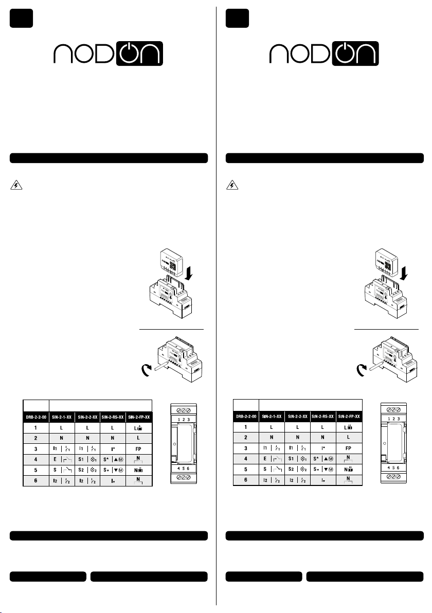
Insérez le module dans le boitier Rail DIN
en respectant le sens d’introduction du module,
le bornier doit se situer à gauche (voir gure 1).
Vériez que les bornes sont bien dévissées et
veillez à ne pas plier les broches situées
à l’intérieur du boitier.
Vissez les 6 vis du module an de xer
les deux éléments entre eux (voir gure 2).
An de faciliter le raccordement, dévissez
les 6 vis du Boitier Rail DIN.
Installez le boitier comprenant le module
sur le Rail DIN du tableau électrique.
Raccordez les bornes suivant le tableau
ci-dessous :
Cut the power supply of the electrical panel.
Unscrew the relay switch terminals you want
to connect.
Insert the relay switch on the DIN Rail Box
while respecting the direction of insertion of the
relay switch, the terminal block must be located
on the left (see gure 1).
Make sure the terminals are well unscrewed and
take care to not fold the pins located inside the
DIN Rail Box.
Screw the 6 screws of the relay switch to x
both elements together (see gure 2).
To facilitate the connection, unscrew
the 6 screws of the DIN Rail Box.
Install the box with the relay switch on
the DIN Rail Box of the electrical panel.
Connect the terminals following the table
below:
INSTALLATION INSTALLATION
gure 2 gure 2
Remettez l’alimentation générale en marche.
Pour l’appairage, appuyez 3 fois sur le bouton
du boitier et référez-vous à la notice du module
selon sa référence :
SIN-2-2-XX, SIN-2-1-XX, SIN-2-RS-XX , SIN-2-FP-XX
Numéro de
borne
Terminal
number
Réf. module Ref. relay switch
Turn the power supply back on.
For pairing, push 3 times on button of the
DIN Rail Box and refer to the relay switch
user guide according to its reference:
SIN-2-2-XX, SIN-2-1-XX, SIN-2-RS-XX, SIN-2-FP-XX.
gure 1 gure 1
• N’utilisez jamais l’appareil s’il n’est pas correctement installé et placé à l’intérieur
d’un tableau électrique conforme aux normes en vigueur.
• Tenez le produit éloigné de tous liquides.
• Never use the device if it is not correctly installed and placed inside an electrical
panel in conformity with the current standards.
• Keep the product far away from liquids.
For user guides in other languages, please visit
www.nodon.fr/notices
For user guides in other languages, please visit
www.nodon.fr/notices
NodOn SAS
121 rue des Hêtres
45590 St CYR EN VAL (FRANCE)
NodOn SAS
121 rue des Hêtres
45590 St CYR EN VAL (FRANCE)
CONTACT CONTACT
PRÉCAUTIONS D’USAGES USE CAUTIONS
SAV SAV

MODO DE EMPLEO GEBRAUCHSANWEISUNG
CAJA CARRIL DIN
PARA MÓDULO CONECTADO
DIN-SCHIENEN-GEHÄUSE
FÜR ANGESCHLOSSENES MODUL
Referencia: DRB-2-2-00
Intensidad máxima: consulte el manual del módulo conectado
Carril DIN compatible: Tipo Ω EN 50022
Módulos compatibles: SIN-2-2-XX, SIN-2-1-XX, SIN-2-RS-XX, SIN-2-FP-XX
Dimensiones: 87x27x58 mm • Peso: 5 g • Garantía: 2años
Artikelnummer: DRB-2-2-00
Maximale Stromstärke : lesen Sie das Handbuch des entsprechenden Moduls
DIN-Schienen-kompatibel: Typ Ω EN 50022
Kompatible Module: SIN-2-2-XX, SIN-2-1-XX,SIN -2-RS-XX, SIN-2-FP-XX
Abmessungen: 87x27x58 mm • Gewicht: 5 g • Garantie: 2 Jahre
PELIGRO DE ELECTROCUCIÓN STROMSCHLAGGEFAHR
Procedimiento de instalación Installationsanleitung
ANTES DE PROCEDER CON LA INSTALACIÓN, ASEGÚRESE DE HABER CORTADO EL
SUMINISTRO ELÉCTRICO PARA EVITAR CUALQUIER PELIGRO DE ELECTROCUCIÓN.
Corte directamente el suministro eléctrico desde el cuadro eléctrico para evitar riesgos de electrocución.
Esta caja para carril DIN ha sido diseñada para un uso conectado a la corriente, por lo que una instalación
inadecuada podría provocar incendios o descargas eléctricas. La caja para carril DIN debe ser instalada
Y conectada siguiendo al pie de la letra las instrucciones de este manual.
NodOn® no asumirá ninguna responsabilidad en caso de accidentes o daños debidos a la inobservancia
de las instrucciones de montaje. Corte el suministro eléctrico antes de realizar cualquier intervención
y no haga ninguna modificación si el LED del módulo situado en la caja para carril DIN está encendido.
VOR DER INSTALLATION MÜSSEN SIE SICHERSTELLEN, DASS DIE STROMVERSORGUNG
UNTERBROCHEN IST. ANSONSTEN BESTEHT DIE GEFAHR EINES STROMSCHLAGS.
Schalten Sie die Stromversorgung direkt am Sicherungskasten ab, um die Gefahr eines Stromschlags
zu vermeiden. Dieses DIN-Schienen-Gehäuse ist für eine Verwendung unter Spannung ausgelegt. Eine
falsche Installation kann einen Brand oder einen Stromschlag verursachen. Das DIN-Schienen-Gehäuse
muss unbedingt unter strengster Einhaltung der Anweisungen dieser Gebrauchsanleitung installiert UND
angeschlossen werden. NodOn® übernimmt keine Haftung für Unfälle oder Schäden, die auf die Nichteinhaltung
der Montageanweisungen zurückzuführen sind. Schalten Sie die Stromversorgung vor jedem Eingriff ab und
nehmen Sie keine Änderungen vor, wenn die LED des Moduls im DIN-Schienen-Gehäuse leuchtet.
Corte el suministro eléctrico general del
cuadro eléctrico.
Desenrosque los terminales del módulo que
desea conectar.
Introduzca el módulo en la caja para carril DIN
respetando el sentido de introducción del módulo;
el terminal debe situarse a la izquierda (ver la
gura 1). Compruebe que los terminales se hayan
desenroscado correctamente y asegúrese de no
doblar las clavijas situadas en el interior de la caja.
Enrosque los 6 tornillos del módulo para jar
ambos elementos entre sí (ver la gura 2).
Para facilitar la conexión, desenrosque
los 6 tornillos de la caja Rail DIN.
Instale la caja que contiene el módulo en el
carril DIN del cuadro eléctrico.
Conecte los terminales del módulo según la
tabla a continuación:
Stellen Sie die allgemeine Stromversorgung des
Schaltkastens ab.
Lösen Sie die Klemmen des Moduls, das Sie
anschließen möchten.
Setzen Sie das Modul in das DIN-Schienen-
Gehäuse ein und achten Sie auf die Einsatzrichtung
des Moduls, die Klemmleiste muss sich links
benden (siehe Abbildung 1). Überprüfen Sie, ob
die Klemmen gut gelöst sind und achten Sie darauf,
dass die Stifte im Kasten nicht geknickt werden.
Ziehen Sie die 6 Schrauben des Moduls fest,
um die beiden Teile aneinander zu befestigen
(siehe Abbildung 2).
Um die Verbindung zu erleichtern, lösen Sie die 6
Schrauben des DIN-Schienen-Gehäuses.
Installieren Sie das Gehäuse mit dem Modul
auf der DIN-Schiene des Schaltkastens.
Schließen Sie die Klemmen gemäß der folgenden
Tabelle an:
INSTALACIÓN INSTALLATION
gura 2 Abbildung 2
Vuelva a poner en marcha el suministro
eléctrico general.
Para el emparejamiento, pulse 3 veces el
botón de la caja y consulte las instrucciones del
módulo según su referencia:
SIN-2-2-XX, SIN-2-1-XX, SIN-2-RS-XX, SIN-2-FP-XX.
Schalten Sie die allgemeine Stromversorgung
wieder ein.
Zur Verbindungsaufnahme drücken Sie dreimal auf die
Gehäusetaste und beachten Sie die Bedienungsanleitung
des Moduls entsprechend der jeweiligen Artikelnummer:
SIN-2-2-XX, SIN-2-1-XX,SIN -2-RS-XX, SIN-2-FP-XX.
gura 1 Abbildung 1
• No utilice nunca el aparato si no está correctamente instalado en el interior
de un cuadro eléctrico según las normas vigentes.
• Mantenga el producto alejado de todo tipo de líquidos.
• Verwenden Sie das Gerät nie, wenn es nicht ordnungsgemäß installiert ist und sich
nicht in einem den geltenden Normen entsprechenden Schaltkasten bendet.
• Halten Sie das Produkt von Flüssigkeiten fern.
www.nodon.fr sección “support” (soporte) [email protected]
For user guides in other languages, please visit
www.nodon.fr/notices
Bedienungsanleitungen in weiteren Sprachen nden
Sie unter: www.nodon.fr/notices
NodOn SAS
121 rue des Hêtres
45590 St CYR EN VAL (FRANCE)
NodOn SAS
121 rue des Hêtres
45590 St CYR EN VAL (FRANKREICH)
CONTACTO KONTAKT
PRECAUCIONES DE USO SICHERHEITSHINWEISE
SERVICIO DE POSTVENTA KUNDENDIENST
ES DE
Número de
terminal
Terminal-
Nummer
Ref. Módulo Artikelnummer Modul
Popular TV Mount manuals by other brands


Sanus Systems
Sanus Systems MF209 manual

CONEN mounts
CONEN mounts JOLLI Assembly instruction

Skyvue
Skyvue NXG-55 installation manual

Thorn
Thorn ALTIS LED AIMING DEVICE installation instructions

Forging Mount
Forging Mount HY9399-B Installation instruction

Lenze
Lenze L-force EZA Series Mounting instructions