manuals.online logo
Brands
  1. Home
  2. •
  3. Brands
  4. •
  5. Forging Mount
  6. •
  7. TV Mount
  8. •
  9. Forging Mount HY9399-B User manual

Forging Mount HY9399-B User manual

M6
M4 M8
STEP 1-1
Select TV Screw Diameter
STEP 1-2
Select TV Screw Length
FLAT BACK ROUND BACK CABLESINSET HOLES
AB
Too Short
Too Long
Correct
150 lbs.
(68 kg)
Does your TV (including accessories)
weigth more than 150 lbs. ( 68 kg )?
—
Perfect!
Y
—
This mount is NOT compatible.
If your TV has a flat back, AND you want your TV closer
to the wall, use the shorter screws (A).
Use the spacers and longer s crews
(B) to accommodate:
·Round/irregular back TVs
·TVs with inset mounting holes
·Extra space needed for cables CAUTION Verify
adequate thread
engagement with the screw/
washer/spacer combination
AND TV bracket .
- Too sho will not hold the TV.
- Too long will damage the TV.
Standard configurations
are shown. For special
applications, or if you
are uncertain about your
hardware selection,
you can see email:
[email protected]
Hand thread screws into the threaded inserts
on the back of your TV to determine which
screw diameter (M4, M6, or M8) to use.
WARNING Exceeding the weight
capacity can result in serious personal
injury or damage to equipment! It is the
installer's responsibility to make sure the
weight of the TV (with accessories) does
not exceed 150 lbs ( 68 kg ).
Drywall with
woo studs?
Perfect!
What is your wall made of?
Please read through these instructions completely to be sure you’re comfortable with
this easy install process. Also check your TV owner’s manual to see if there are any
special requirements for mounting your TV.
If you do not understand these instructions or have doubts about the safety of the
installation, assembly or use of this product, please contact US via: [email protected]
CAUTION:
Avoid potential personal injuries and property damage!
●This product is designed for use in wood stud/concrete walls DO NOT install into
drywall
●The wall must be capable of supporting ve times the weight of the TV and mount combined
●Do not use this product for any purpose not explicitly speci ed by manufacturer
●Manufacturer is not responsible for damage or injury caused by incorrect assembly or use
Solid concrete or
conc et block?
Tools Needed
Hardware Included
WARNING: This product
contains small items that could
bea choking hazard if swallowed.
Before starting assembly,
verify all parts are included
and undamaged. If any parts
are missing or damaged, do
not return the damaged item to
your dealer; contact Customer
Service.
Never use damaged parts!
NOTE: Not all parts and
hardware included will be used.
Concrete Install
Hammer Drill Bit
3/8 in.
(10 mm)
Concrete
Wood Stud Install
AwlStud Finder
5/32 in.
( 4 mm)
Wood
Drill Bit
Pencil Screwdriver
Tape
Measure Electric
Drill
1/2 in.
(13 mm)
Socket
Wrench
fi
fi
No
es
Getting Started
:
d
er
rt
:
DUAL LONG ARM
TV WALL MOUNT
Model HY9399-B
Specification Sheet
Installation Instruction
Supplied Parts List
(4)M8 Washer-F
(4)M6x35 Bolt-K
(8)5mm M6/M8
Spacer-B
(6)Lag Bolt Washer-X
(1)Left Monitor Bracket
(4)M4x12 Bolt-G
(4)M8x20 Bolt-L
(4)20mm M6/M8
Spacer-C
(6)M8x90mm Lag Bolt-Y
(1)Right Monitor Bracket
(4)M4x30 Bolt-H
(4)M8x35 Bolt-M
(4)M4 Washer-D
(6)M10x80mm
Concrete Anchor-Z
(1)Allen Key
(4)M6 Washer-E
(4)M6x20 Bolt-J
(4)M4 Spacer-A
(4)M8x45 Bolt-N
(1)Wall Plate
(2)Plastic Knob
Pls install the Plastic Knob on the Monitor
Bracket as left diagram before do the next step.
Pls note the two knobs should be installed in
the opposite way on the two monitor brackets.
(1)bubble Level-I
(3)VELCRO TIE
(1)HDMI Cable
(1)wallplate template
I
24 in or16 in.
(609mm/406 mm)
2-1 2-2 2-3 2-4
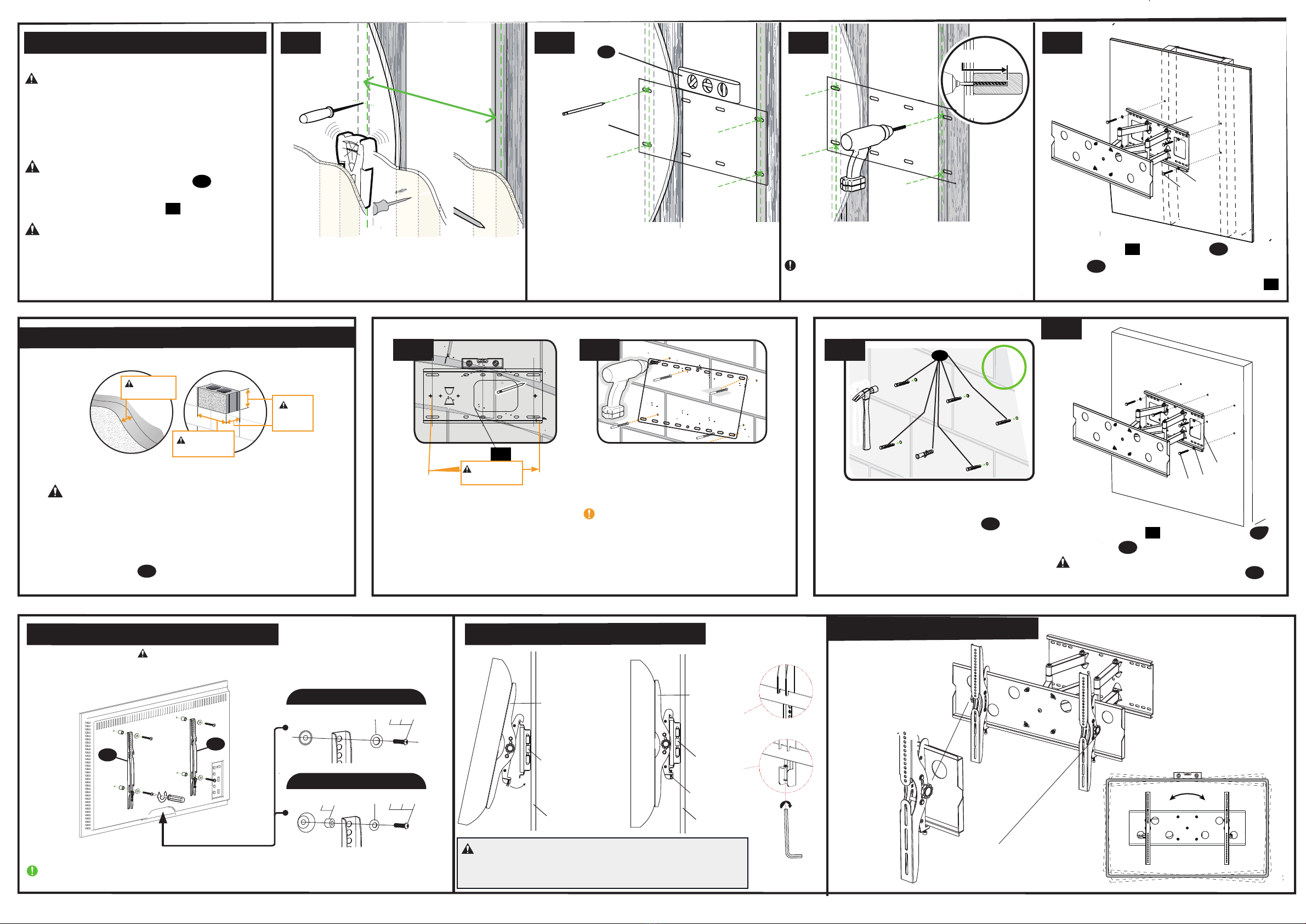
STEP 3 Attach TV Brackets to TV back STEP 4 Attach TV to the arm assembly
Made in China.
Position the wallplate template at your desired height
and line up the holes with your stud center line.
Level the wall plate and mark the holes.
Drill pilot holes using a 5/32 in (4mm) diameter drill bit.
of 3.5in.(90 mm).Be sure to drill into the center of the stud.
IMPORTANT:
Pilot holes must be drilled to a depth
CAUTION: property damage!
●Minimum solid concrete thickness: 8 in. (203 mm).
●Minimum concrete block size: 8 x 8 x 16 in. (203 x 203 x 406 mm)
●Minimum horizontal space between fasteners: 16 in
(406 mm).
●Mount wall plate directly onto the concrete surface.
Position wallplate template
at your desired height. Level, then
mark the six hole locations.
Drill six pilot holes using a 3/8 in.
(10 mm) masonry drill bit.
Min.
8 in.
(203 mm)
Min. 8 in.
(203 mm)
Min. 16 in.
(406 mm)
CAUTION: Be sure the anchors are
seated flush with the concrete surface.
Install wall plate
DO NOT over-tighten the screws.
and screws
holding power of screws
with six washers
01
IMPORTANT : Ensure TV bracket is securely fastened before moving on to the next step.
CAUTION:Avoid potential personal injuries and property damage!
DO NOT use a power screwdriver for this step
STEP 2A Wall Plate Install( Wood Stud )
STEP 2B Wall Plate Install( Solid Concrete or Concrete Block )
½ x 3½ in. (38 x 89 mm)
Y MUST BE
CAUTION: Avoid potential personal injuries
and property damage!
●Drywall covering the wall must not exceed
5/8 in. (16 mm)
●Minimum wood stud size: common 2 x 4 in.
(51 x 102 mm) nominal 1
CAUTION: A
01 .
void potential personal injury
or property damage! All lag bolts
firmly tightened to prevent unwanted
movement of the wall plate
CAUTION: Ensure the wall plate is securely
fastened to the wall before continuing on to the
next step. the studs by finding the stud edges using an awl,
a thin nail, or an edge-to-edge stud finder.
Locate your studs. Verify and mark the center of
Install wall plate
washers
they are pulled firmly a gainst the wall plate
.Tighten the lag bolts only until
using lag bolt and
01
01
01
Y
X
Z
22
X
Y
3.5 in (90mm)
5/32 in.
( 4 mm)
Avoid potential personal injuries and
2A-1 2A-2 2A-3
01
Min. 16 in.
(406 mm)
drilled to a depth of 3.5 in ( 90 mm ).
Never drill into the mortar between blocks.
IMPORTANT:Pilot holes must be
Z
Insert six concrete anchors
( 10x80mm ) to the wall
CAUTION: Improper use could reduce the
Y
aFlat Back
D E F G J L
bRound Back/Extra Space
CAUTION: Avoid potential personal injury or property damage!
Make sure your locking screws are tightened BEHIND the mounting plate
so the TV is securely fastened in place.
STEP 5 Tilt and level adjustment
2A-4
A B C
Wall plate
D E F H K M Safety Bolt
Wall Plate Wall Plate
Monitor Brackets Monitor Brackets
Wall Wall
Allen key
Levelling Mount(TV)
by hand dire ctly
knobs for tilt
angles adjustment
Wall Plate
YX
Wall Plate
24” 16"
(609mm/406mm)
YX

Other Forging Mount TV Mount manuals

Forging Mount HY9397-B User manual

Forging Mount

Forging Mount HY9397-B User manual

Forging Mount HY 9001 User manual

Forging Mount

Forging Mount HY 9001 User manual

Forging Mount HY9395-B User manual

Forging Mount

Forging Mount HY9395-B User manual

Forging Mount FM9388-B User manual

Forging Mount

Forging Mount FM9388-B User manual

Forging Mount HY9190 User manual

Forging Mount

Forging Mount HY9190 User manual

Forging Mount FM4532 User manual

Forging Mount

Forging Mount FM4532 User manual

Forging Mount HY9440 User manual

Forging Mount

Forging Mount HY9440 User manual

Forging Mount HY4001 User manual

Forging Mount

Forging Mount HY4001 User manual

Forging Mount HY9189 User manual

Forging Mount

Forging Mount HY9189 User manual

Forging Mount HY4107 User manual

Forging Mount

Forging Mount HY4107 User manual

Forging Mount HY9001-B User manual

Forging Mount

Forging Mount HY9001-B User manual

Forging Mount HY9400-B User manual

Forging Mount

Forging Mount HY9400-B User manual

Forging Mount HY4114 User manual

Forging Mount

Forging Mount HY4114 User manual

Forging Mount HY9001-B User manual

Forging Mount

Forging Mount HY9001-B User manual

Forging Mount FM9180-B User manual

Forging Mount

Forging Mount FM9180-B User manual

Forging Mount HY9391-B User manual

Forging Mount

Forging Mount HY9391-B User manual

Forging Mount HY9393-B User manual

Forging Mount

Forging Mount HY9393-B User manual

Forging Mount HY9389-B User manual

Forging Mount

Forging Mount HY9389-B User manual

Popular TV Mount manuals by other brands

ACT AC8370 installation manual

ACT

ACT AC8370 installation manual

Belkin F4D051 instruction sheet

Belkin

Belkin F4D051 instruction sheet

AG Neovo FMC-06 installation manual

AG Neovo

AG Neovo FMC-06 installation manual

Sanus VSF409 instruction manual

Sanus

Sanus VSF409 instruction manual

Echogear EGLL1 instruction manual

Echogear

Echogear EGLL1 instruction manual

Sony SU-WL700 instructions

Sony

Sony SU-WL700 instructions

Loxit Hi-Lo 600 manual

Loxit

Loxit Hi-Lo 600 manual

Sanus CLASSIC MSF07c instruction manual

Sanus

Sanus CLASSIC MSF07c instruction manual

Insignia 09-0878 user guide

Insignia

Insignia 09-0878 user guide

Techly ICA-PLB 162M user manual

Techly

Techly ICA-PLB 162M user manual

Clas Ohlson ML-P02M manual

Clas Ohlson

Clas Ohlson ML-P02M manual

Mountup MU0010 Installation instruction

Mountup

Mountup MU0010 Installation instruction

Lenze L-force EZA Series Mounting instructions

Lenze

Lenze L-force EZA Series Mounting instructions

Technimount System PRO 121-GR1 Series user guide

Technimount System

Technimount System PRO 121-GR1 Series user guide

Stell SHO 1027 Universal Mounting Instructions

Stell

Stell SHO 1027 Universal Mounting Instructions

Bauhn ASWM65-0320 installation guide

Bauhn

Bauhn ASWM65-0320 installation guide

Rosewill RMS-MT3710 user manual

Rosewill

Rosewill RMS-MT3710 user manual

Pyle PWLB003 installation guide

Pyle

Pyle PWLB003 installation guide

manuals.online logo
manuals.online logoBrands
  • About & Mission
  • Contact us
  • Privacy Policy
  • Terms and Conditions

Copyright 2025 Manuals.Online. All Rights Reserved.