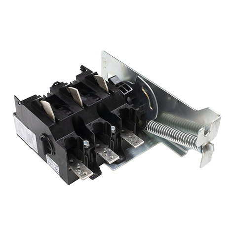
NOJA Power VISI-SWITCH OLB15-16-800 User manual

®
VISI-SWITCH
®
VISI-SWITCH®OLB15-16-800
12KV MODEL
PRODUCT GUIDE

Introduction
NOJA Power’s VISI-SWITCH®is a solid dielectric load
break switch designed for manual isolation in a three-
phase electricity distribution grid feeder. Unique to
this switch, is the viewing window embedded in the
bushings, allowing an operator to see the actual point
of isolation. Through the viewing window, an operator
can see the isolator electrical contacts when the switch
is closed and visible isolation when the switch is open,
guaranteeing that the circuit is isolated.
It also features vacuum interrupters with solid dielectric
insulation and a unique and patent-pending drive
mechanism ensuring safe operational sequence.
NOJA Power’s VISI-SWITCH®OLB15-16-800 has a
rated maximum voltage of 12 kV, a rated continuous
current of 800 A and a short time current withstand of
16 kA (for 3 seconds).
Each phase is comprised of a vacuum interrupter with
solid dielectric insulation and a built-in isolator to provide
physical isolation in accordance with the requirements
of insulation coordination standards IEC 60071-1
Insulation co-ordination – Part 1: Definition, Principles
and Rules and IEC 60071-2 Insulation co-ordination –
Part 2: Application Guide.
The VISI-SWITCH®features a unique and patent-
pending drive mechanism which connects the vacuum
interrupters to the isolators and guarantees both parts
of the switch will open once operation is initiated. The
sequencing of the complete switching operation is
VISI-SWITCH® WITH SURGE
ARRESTORS
VISI-SWITCH® SIDE VIEW VISI-SWITCH®FRONT VIEW
INTRODUCTION
1. Product Guide VISI-SWITCH®

Introduction
VISIBLE ISOLATOR OPEN POSITION
VISIBLE ISOLATOR PULLS BACK INTO
OPEN POSITION
VISIBLE ISOLATOR CLOSED POSITION
1.
2.
Product Guide VISI-SWITCH®
dictated by the drive mechanism which rapidly opens the
vacuum interrupters to break the current and then, after
a short delay, opens the isolators. The viewing window
embedded in the isolator bushings can be seen from
the ground allowing maintenance staff to confirm that
the switch has been isolated prior to commencing work.
The product has been extensively type tested by
independent laboratories to ensure long life and reliability
under the harshest environmental conditions. The VISI-
SWITCH®can operate in extreme temperatures, over
a -40 to 55oC temperature range, 0 to 100 percent
humidity, and meets specified ratings up to a height of
1000 m (functional up to 3000 m with derating). The unit
is designed to cope with exposure to salt spray, dust,
smoke and corrosive gases, vapours and liquids. The
viewing window is scratch resistant and can withstand
impact such as hail according to IK08.
Utilities employ three-phase load break switches to
isolate sections of feeders for maintenance work. In
recent years, older air break switches, which could not
be operated while the feeder was under load have been
replaced by gas switches. While enclosed gas switches
address the reliability deficiencies of air break switches,
it comes at a cost of compromised safety because
maintenance staff can no longer visually check that
all three phases are isolated before starting work on
the feeder. SF6 has also been identified as the most
potent greenhouse gas and utilities will most likely incur
the cost of disposing the SF6 gas at the end of life of
the switch.
NOJA Power’s engineers have designed the
VISI-SWITCH®to overcome the drawbacks of gas
load break switches providing the linesmen with visible
break confirmation that the switchgear has isolated the
line before commencing work. Furthermore, the units
are far more environmentally friendly than existing
solutions because the solid dielectric eliminates the use
of a potent greenhouse gas. Like all other switchgear
products designed and manufactured by NOJA Power it
also features controlled arc fault venting.
The VISI-SWITCH®demonstrates NOJA Power’s
ongoing commitment to the environment, quality and
safety making the VISI-SWITCH®OLB15-16-800 the
ideal choice for today’s smart grids.

Introduction
3. Product Guide VISI-SWITCH®
NOJA Power’s VISI-SWITCH®is an enclosed three
phase load break switch with visible isolation. It is used
to isolate sections of feeders for maintenance work so
that work can be carried out in a safe manner.
The VISI-SWITCH®includes an isolator and
vacuum interrupter for each phase that are serially
interconnected for load break application. A mechanical
driving mechanism is provided for driving open and
closed each pair of electrical contacts and is configured
to control the sequence of the opening and closing of
the contacts. The vacuum interrupter is opened first
to break current flow and then after a short delay the
isolators are opened to disconnect the electrical circuit.
When closing, the isolator closes first and then the
vacuum interrupter, making the current.
The operator can manually open and close the contacts
of both the isolator and interrupter from the ground
with a single motion using either an extended hook
stick which reaches directly to the switch or a shorter
hook stick which connects to an insulated down rod
extending from the switch.
The advantage of the switch is that the operator can
view the isolator contacts through the viewing window,
thereby readily determining the state of the switch from
the ground. In particular, the operator can confirm that
there is a visible break i.e. the contacts are open and
that the associated circuit is safely isolated.
The switch includes isolator bushings in which the
electrical isolator contacts are located, a metal tank in
which the driving mechanism is located, and interrupter
bushings in which the interrupter contacts are located.
The bushings and the tank are sealed together and
impede the ingress of moisture thereby suiting the
assembly to outdoor use. The tank is manufactured
from powder coated stainless steel and is arc-fault
vented. It has a 30 year operating life and the entire
device is rated to IP65.
OVERVIEW
VISI-SWITCH®FRONT VIEW
VISI-SWITCH®VISIBLE ISOLATOR
OPEN STATE
VISI-SWITCH®VISIBLE ISOLATOR
CLOSED STATE

Introduction 4.
Product Guide VISI-SWITCH®
INSULATION SYSTEM
VISIBLE BREAK WINDOW
The insulation system consists of the conductor system
embedded in solid dielectric. External insulation is
provided by silicone bushings outside of the powder
coated stainless steel tank. Silicone Rubber Boots fitted
over the bushings provide the necessary clearances
and creepages required for the various ratings.
Surge Arrestors can be mounted on all six (6) bushings
and earthed through the tank. Explosive tail surge
arrestors may be used and there are mounting options
for the surge arrestors both at the top and bottom of
the switch.
The viewing window allows a clear view of the state of
the switch from an operator standing on the ground. The
isolator contact is coated with an iridescent/reflective
paint in the colour red and can be easily seen through
the window even at night with the use of a torch.
The window is designed to remain transparent during
the entire life of the switch, without any discolouration.
It is scratch resistant and can withstand extreme
temperatures and weather conditions such as hailstorms
and sandstorms. IK08 impact ratings are met on all
parts of the switch including the viewing window.
VISI-SWITCH®WITH
VISIBLE ISOLATOR
IN OPEN POSITION
VISI-SWITCH®WITH TOP
SURGE ARRESTORS
ARRANGEMENT
VISI-SWITCH®WITH
BOTTOM SURGE
ARRESTORS
ARRANGEMENT
VISI-SWITCH®WITH TOP
SURGE ARRESTORS
ARRANGEMENT
VISI-SWITCH® WITH
VISIBLE ISOLATOR IN
CLOSED POSITION

Introduction
5. Product Guide VISI-SWITCH®
INSTALLATION
The switch can be mounted on timber poles with a
keyhole arrangement or concrete poles using banded
straps. The following types of installations are supported:
• Mounted to the pole above the powerline
• Mounted to the pole below the powerline
Prior to mounting on the pole, the switch must be fitted
to the mounting bracket and all surge arrestors and
cable tails fitted.
The hanging bracket can be mounted above or below
the cross arm depending on the customer’s preferred
installation location.
The switch is completely symmetrical so it can be
mounted with the hook stick operator facing toward the
pole or away from the pole.
The switch assembly can be fixed to the pole via a
crane, pole mounted hoist or EPV. Lifting points are
provided to allow for lifting of the assembled switch.
The switch is to remain within 15 degrees of horizontal
whilst lifting. An M12 stud on the switch is provided for
an earth connection. A minimum thickness of 35mm2
copper conductor must be used.
Standard hand tools will be all that is required to
complete the installation, namely ring, adjustable
VISI-SWITCH® POLE MOUNTING ARRANGEMENT
(ABOVE THE POWER LINE WITH FEET)
VISI-SWITCH® POLE MOUNTING ARRANGEMENT
(BELOW THE POWER LINE)
TUNNEL
CONNECTOR
TWO HOLE NEMA
PAD OPTION
spanners or allen key. All fasteners must be
capable of withstanding the maximum load
applied by a man with a standard spanner.
VISI-SWITCH® POLE
MOUNTING ARRANGEMENT

Introduction 6.
Product Guide VISI-SWITCH®
OPERATION
DIMENSIONS
The VISI-SWITCH®can be manually operated from the
ground in one single motion using an extended hook
stick which reaches directly to the switch.
VISI-SWITCH® CLOSED STATEVISI-SWITCH®OPEN STATE
1082.3 [46.2]
879.4 [34.6]
1421.7 [55.4]
250.0 [9.8]
1179.0 [46.4]
333.0 [13.3]
333.0 [13.3]
1082.3 [46.2]
879.4 [34.6]
1421.7 [55.4]
250.0 [9.8]
1179.0 [46.4]
333.0 [13.3]
333.0 [13.3]
VISI-SWITCH® SIDE VIEW
(DIMENSIONS IN INCHES SHOWN IN BRACKETS)
VISI-SWITCH® FRONT VIEW
(DIMENSIONS IN INCHES SHOWN IN BRACKETS)
An insulated down rod, extending from the switch,
can be used to move the operating mechanism
further down the pole to allow a shorter hook
stick to be used.

®
NOJA-5039-01
NOJA Power®, OSM® and VISI-SWITCH®are registered trademarks of NOJA Power Switchgear Pty Ltd. This document is copyright and is intended for users and distributors of NOJA Power Switchgear product. It contains information that is the intellectual property of NOJA Power Switchgear and
the document, or any part thereof, should not be copied or reproduced in any form without written permission from NOJA Power Switchgear. NOJA Power®, OSM®and VISI-SWITCH®are registered trademarks of NOJA Power Switchgear and should not be reproduced or used in any way without
written authorization.
NOJA Power Switchgear applies a policy of ongoing development and reserves the right to change product without notice. NOJA Power Switchgear does not accept any responsibility for loss or damage incurred as a result of acting or refraining from action based on information in this User Manual.
OLB15-16-800
3
50/60 Hz
E3
C1
M2
12kV
28kV
28kV
95kVp
110kVp
32kV
800A
800A
16kA – 3s
16kA
41.6kA
800A
10A
4A
20A
31.5A
10000
10000
10
16kA – 0.2s
-40oC to +55oC
0 – 100%
1000m
IP65
IK08
<150kg
Part Number
Number of Phases
Frequency
Switch Electrical Endurance Class
Switch Capacitive Switching Class
Switch Mechanical Endurance Class
Rated Maximum Voltage
Dry Power Frequency Withstand Voltage
Wet Power Frequency Withstand Voltage
Impulse Withstand phase to phase and phase to earth
Impulse Withstand across the isolator without the VI
Dry Power Frequency across the isolator without the VI
Rated Continuous Current
Rated Distribution Line Closed-Loop Breaking Current
Short time current withstand
Fault Make Capacity, RMS
Fault Make Capacity, Peak
Mainly Active Load Breaking
Rated Cable-Charging Breaking Current
Rated Line-Charging Breaking Current
Rated Cable and Line Charging Breaking Current under Earth Fault Conditions
Rated Earth Fault Breaking Current
Mechanical Operations
Full Load Operations
Fault make capacity operations
Internal arc fault rating
Ambient temperature
Humidity
Altitude
IP Rating
Impact Rating
Fully Dressed Including surge arrestors cables and mounting bracket
(Combined Isolator and VI Switchgear Ratings)
Scan to view
NOJA Power
website
Distributor
NOJA POWER EUROPE
SALES OFFICE
NOJA Power Switchgear Pty Ltd
Sebastianstrasse 38, 53115
Poppesldorf, Bonn, Germany
Phone: +49 (0) 228 8236 9408
Email: sales@nojapower.eu
Web: www.nojapower.eu
NOJA POWER AUSTRALIA
CORPORATE OFFICE & FACTORY
NOJA Power Switchgear Pty Ltd
16 Archimedes Place, Murarrie
Brisbane Qld 4172
Australia
Phone: +61 (7) 3907 8777
Fax: +61 (7) 3399 6777
Email: sales@nojapower.com.au
Web: www.nojapower.com.au
NOJA POWER UK
SALES OFFICE
NOJA Power Limited
Hyde Park House, Cartwright Street
Hyde, Cheshire SK14 4EH
United Kingdom
Phone: +44 (0) 7805 352 502
Email: sales@nojapower.co.uk
Web: www.nojapower.co.uk
NOJA POWER BRAZIL
OFFICE & FACTORY
NOJA Power do Brasil Ltda
Avenida Pierre Simon de Laplace,
965A Techno Park – Campinas – SP
Brasil
Phone: +55 (19) 3283 0041
Fax: +55 (19) 3283 0041
Email: vendas@nojapower.com.br
Web: www.nojapower.com.br
NOJA POWER USA
SALES OFFICE
NOJA Power, LLC
Office: 333 SE 2nd Ave.
Suite 2053, Miami, FL 33131
United States of America
Phone: +1.484-515-4880
Email: sales@nojapower.com
Web: www.nojapower.com
Table of contents
Popular Switch manuals by other brands
Whelen Engineering Company
Whelen Engineering Company PCCS9RW installation guide
schmersal
schmersal EX-ZQ 900 operating instructions
IFM
IFM KN Series operating instructions
Lightware
Lightware UCX-2x1-HC30 user manual
LGC wireless
LGC wireless InterReach Unison Installation & operation manual
JETI model
JETI model ENLINK 2RS Plus user manual

