Nokia RM-305 User manual

Service Manual
RM-305; RM-306 (Nokia 1650)
Mobile Terminal
Part No: 9200071 (Issue 2)
Nokia Customer Care
COMPANY CONFIDENTIAL
Copyright © 2007 Nokia. All rights reserved.

1 — General information
Nokia Customer Care
Issue 2 COMPANY CONFIDENTIAL Page 1 –1
Copyright © 2007 Nokia. All rights reserved.

Table of Contents
Product selection....................................................................................................................................................1–5
Display and keypad features .................................................................................................................................1–5
Features...................................................................................................................................................................1–5
Hardware features ............................................................................................................................................1–5
Software features..............................................................................................................................................1–6
UI features..........................................................................................................................................................1–6
Mobile enhancements.......................................................................................................................................1–7
Technical specifications.........................................................................................................................................1–8
General specifications.......................................................................................................................................1–8
Battery endurance.............................................................................................................................................1–8
Environmental conditions ................................................................................................................................1–8
Electrical characteristics ...................................................................................................................................1–9
List of Tables
Table 1 Power.........................................................................................................................................................1–7
Table 2 Car...............................................................................................................................................................1–7
Table 3 Audio..........................................................................................................................................................1–7
Table 4 Normal and extreme voltages.................................................................................................................1–9
Table 5 Current consumption................................................................................................................................1–9
List of Figures
Figure 1 RM-305/306 Product Picture ..................................................................................................................1–5
RM-305; RM-306
General information
Issue 2 COMPANY CONFIDENTIAL Page 1 –3
Copyright © 2007 Nokia. All rights reserved.

Product selection
The RM-305 is the EU version of the telephone with a dual band transceiver unit designed for the GSM900
and GSM1800 networks.
The RM-306 is the US version of the telephone with a dual band transceiver unit designed for the GSM850
and GSM1900 networks.
Figure 1 RM-305/306 Product Picture
Display and keypad features
• High resolution color display (128x160 pixels)
• 4UI-style, 4-way navigation key including selection key
• Rubber keymat
Features
Hardware features
• GSM E900/1800 (EU/APAC version)
• GSM 850/1900 (US version)
• Gefion Engine, UPP Costo, 4 layer PWB
• 7-11 earpiece +13mm speaker audio solution
• AMR/HR/FR(US version not included)/EFR codecs
• Internal antenna
• Charger plug
RM-305; RM-306
General information
Issue 2 COMPANY CONFIDENTIAL Page 1 –5
Copyright © 2007 Nokia. All rights reserved.

• System connector: Easy flash II
• Headset connector
• Internal vibrator
• User changeable front- and back covers
• SIM (1.8 and 3.0 V)
Software features
• OS: CUI
• UI Style: Jack 4
• Phone sharing (Multi-phonebook and call duration record)
• MP3-grade ringing tones and 32 polyphonic ringing tones.
• FM Radio
• Flash light
• Analog clock
UI features
Messaging • SMS messaging
• Predictive text input
• Asia-Pacific: English, Chinese Simplified, Chinese Traditional, Thai,
Philipino, Vietnamese, Bahasa Indonesia, Bahasa Malaysia, Hindi
• Europe and Africa: Danish, Dutch, English, French, Finnish, German,
Icelandic, Italian, Portugese, Spanish, Swedish, Norwegian, Turkish, Greek,
Bulgarian, Ukranian, Hebrew, Arabic, Slovakian, Czech, Hungarian, Polish,
Romanian, Serbian, Croatian, Slovenian, Russian, Estonian, Latvian,
Lithuanian
• Non-predictive text input: Farsi, Zulu, Xhosa, Sesotho, Swahili, Merathi,
Tamil, Gujarati, Bengali
Memory functions • Phone book (up to 200 entries in internal phone memory; up to 250 entries
on simcard.)
Connectivity • Plug and play connector
Call management • Speed dialing: up to 8 names (keys 2-9)
•Last number redial from dialed calls list (dial key brings out the dialed calls
list)
• Automatic redial (max 10 attempts)
• Automatic answer (works with headset or car kit only)
• Call waiting, call hold, call divert, and call timer
• Automatic and manual network selection
• Vibrating alert
Voice features • Integrated handsfree speaker
RM-305; RM-306
General information
Page 1 –6 COMPANY CONFIDENTIAL Issue 2
Copyright © 2007 Nokia. All rights reserved.

Personalise • Graphics, icons, animations, logos
•3 games available . The selection of games depends on the region the phone
is sold in (Snake, Dice, Rapid Rolls, Pocket Carrom.)
• Ringing tones: Polyphonic tones and MP3 grade sound ringingtones.
Phone features • Phone Features
• Demo application accessible both with and without SIM mode.
• Speaking clock & speaking alarm
• Prepaid tracker (network dependent service)
Mobile enhancements
Mobile enhancements for RM-305/306
Table 1 Power
Type Name
BL-5C Battery 1020 mAh Li-Ion
AC-3 Light charger
AC-4 Light charger
AC-5 Light charger
HH-12 Holder Easy Mount
CA-44 Charger Adapter
Table 2 Car
Type Name
CR-39 Nokia universal holder
Table 3 Audio
Type Name
HS-40 Headset
HS-47 Mono Headset
HDA-11 TTY Adapter
MD-3 Music Speakers
MD-4 Mini Speakers
RM-305; RM-306
General information
Issue 2 COMPANY CONFIDENTIAL Page 1 –7
Copyright © 2007 Nokia. All rights reserved.

Technical specifications
General specifications
Unit Dimension (mm) Weight (g) Volume (cc)
Transceiver with Li-Ion
battery pack
104x43x17 80 70
Battery endurance
Talk time
Battery: BL-5C 1020 mAh Up to 300 min
Standby time
Battery: BL-5C 1020 mAh Up to 380 hours
Note: Variation in operation times will occur depending on SIM card, network settings and usage.
Talk time is increased by up to 30% if half rate is active and reduced by 5% if enhanced full rate is
active.
Environmental conditions
Environmental
condition Ambient temperature Notes
Normal operation -15 oC ... +55 oCSpecifications fulfilled
Reduced performance -30 ...15 oC and +55oC ... +70 oCOperational only for short periods
Intermittent or no
operation -40 oC ... -30 oC and +70 oC ... +85oCOperation not guaranteed but an
attempt to operate will not damage
the phone
No operation or
storage <-40 oC and >+85 oCNo storage. An attempt to operate
may cause permanent damage
Charging allowed -15 oC ... +55 oC
Long term storage
conditions 0 oC ... +85 oC
Humidity and water
resistance
Relative humidity range is 5 to 95%.
Condensed or dripping water may
cause intermittent malfunctions.
Protection against dripping water
has to be implemented in (enclosure)
mechanics.
Continuous dampness will cause
permanent damage to the module.
RM-305; RM-306
General information
Page 1 –8 COMPANY CONFIDENTIAL Issue 2
Copyright © 2007 Nokia. All rights reserved.

Electrical characteristics
Table 4 Normal and extreme voltages
Voltage Voltage (V) Condition
General conditions
Nominal voltage 3.90V a
Lower extreme voltage 3.30V b
Higher extreme voltage 4.30V c
HW shutdown voltages
Vmstr+ 2.1V ± 0,1V Off to on
Vmstr- 1.9V ± 0,1V On to off
SW shutdown voltages
SW shutdown 3. 1V In call
SW shutdown 3. 2V In idle
Min operating voltage
Vcoff+ 3. 1V ± 0,1V Off to on
Vcoff- 2. 8V ± 0,1V On to off
HW reset demands
Min 1. 0V d
Max --
a. The nominal voltage is defined as being 15% higher than the lower extreme voltage. TA will test with this
nominal voltage at an 85% range (0.85x3.9V a3.3V).
b. This limit is set to be above SW shutdown limit in TA.
c. During fast charging of an empty battery, this voltage might exceed this value. Voltages between 4.20 and
4.60 might appear for a short while.
d. The minimum battery cell voltage required for the reset circuitry to turn on. This is not confirmed by
measures at pt.
Table 5 Current consumption
Condition Min Typical Max Unit
Call (MoU)
GSM 850
(E)GSM 900
GSM 1800
GSM 1900
.
225
208
188
168
mA
Idle (MoU) 2.0 mA
Power off 25 30 45 µA
RM-305; RM-306
General information
Issue 2 COMPANY CONFIDENTIAL Page 1 –9
Copyright © 2007 Nokia. All rights reserved.

2 — Service Tools
Nokia Customer Care
Issue 2 COMPANY CONFIDENTIAL Page 2 –1
Copyright © 2007 Nokia. All rights reserved.

Table of Contents
Service tools............................................................................................................................................................2–5
ACF-8...................................................................................................................................................................2–5
AXS-4...................................................................................................................................................................2–5
CA-106DS ............................................................................................................................................................2–5
CA-10DS ..............................................................................................................................................................2–5
CA-111DS ............................................................................................................................................................2–6
CA-112DS ............................................................................................................................................................2–6
CA-28DS ..............................................................................................................................................................2–6
CA-31D ................................................................................................................................................................2–6
CA-35S.................................................................................................................................................................2–7
CA-41PS...............................................................................................................................................................2–7
CA-5S...................................................................................................................................................................2–7
DA-49 ..................................................................................................................................................................2–7
DAU-9S................................................................................................................................................................2–8
FLC-2 ...................................................................................................................................................................2–8
FLS-4S..................................................................................................................................................................2–8
FLS-5 ...................................................................................................................................................................2–8
FPS-10.................................................................................................................................................................2–9
FPS-8 ...................................................................................................................................................................2–9
JBV-1 ................................................................................................................................................................ 2–10
MJ-130.............................................................................................................................................................. 2–10
PCS-1................................................................................................................................................................ 2–10
PKD-1 ............................................................................................................................................................... 2–11
RJ-164 .............................................................................................................................................................. 2–11
SA-41................................................................................................................................................................ 2–11
SF-10................................................................................................................................................................ 2–11
SF-56................................................................................................................................................................ 2–11
SPS-1................................................................................................................................................................ 2–12
SRT-6................................................................................................................................................................ 2–12
SS-54................................................................................................................................................................ 2–12
ST-30................................................................................................................................................................ 2–12
ST-32................................................................................................................................................................ 2–13
SX-4.................................................................................................................................................................. 2–13
XCS-4 ................................................................................................................................................................ 2–13
XRS-6................................................................................................................................................................ 2–13
Service software concept.................................................................................................................................... 2–14
POS (Point of Sales) flash concept ................................................................................................................ 2–14
POS flash concept with FLS-5 ........................................................................................................................ 2–15
FPS-10 Prommer box flash concept.............................................................................................................. 2–16
JBV-1 flash concept with FPS-10 ................................................................................................................... 2–17
JBV-1 flash concept with FPS-8 ..................................................................................................................... 2–18
Module jig (MJ-130) service concept............................................................................................................. 2–19
List of Figures
Figure 2 POS flash concept ................................................................................................................................. 2–14
Figure 3 POS flash concept with FLS-5............................................................................................................... 2–15
Figure 4 FPS-10 Prommer box flash concept.................................................................................................... 2–16
Figure 5 JBV-1 flash concept with FPS-10 ......................................................................................................... 2–17
Figure 6 JBV-1 flash concept with FPS-8............................................................................................................ 2–18
RM-305; RM-306
Service Tools
Issue 2 COMPANY CONFIDENTIAL Page 2 –3
Copyright © 2007 Nokia. All rights reserved.

Figure 7 Module jig service concept .................................................................................................................. 2–19
RM-305; RM-306
Service Tools
Page 2 –4 COMPANY CONFIDENTIAL Issue 2
Copyright © 2007 Nokia. All rights reserved.

Service tools
The table below gives a short overview of service tools that can be used for testing, error analysis and repair
of product RM-305; RM-306, refer to various concepts.
ACF-8 Universal power
supply
ACF-8 universal power supply is used to power FPS-8. ACF-8 has 6V DC
and 2.1A output.
AXS-4 Service cable
The AXS-4 D9-D9 service cable is used to connect two 9 pin D
connectors for example between PC and FPS-8.
The cable length is 2 meters.
CA-106DS Easy flash II cable
The cable is used for connecting phone DC port to the flash prommer
FPS-10.
CA-10DS Bi-directional
Parallel Cable
Bi-Directional parallel cable included in FPS-8 sales pack.
RM-305; RM-306
Service Tools
Issue 2 COMPANY CONFIDENTIAL Page 2 –5
Copyright © 2007 Nokia. All rights reserved.

CA-111DS Easy flash II cable
The cable is used for connecting phone DC port to either POS flashing
device FLS-4S or to the PROMMER box FPS-11.
CA-112DS Easy flash II cable
The CA-112DS easy flash II cable is used for connecting phone DC port
to the PROMMER facilities (FLS-5, FPS-20).
CA-28DS Service data cable
The CA-28DS service cable is used to connect FLS-4S to the POS flash
adapter for supplying a controlled operating voltage and data
connection.
Note: Old XCS-1 cable can be used as well.
CA-31D USB cable
The CA-31D USB cable is used to connect FPS-10 or FPS-11 to a PC. It is
included in the FPS-10 and FPS-11 sales packages.
RM-305; RM-306
Service Tools
Page 2 –6 COMPANY CONFIDENTIAL Issue 2
Copyright © 2007 Nokia. All rights reserved.
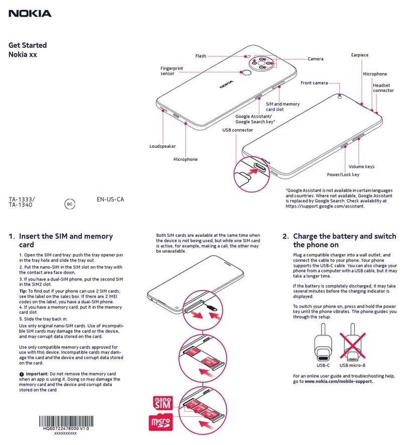
CA-35S Power cable
CA-35S is a power cable for connecting, for example, the FPS-10 flash
prommer to the Point-Of-Sales (POS) flash adapter.
CA-41PS Power cable
Power cable for connection of e.g. the JBV-1 docking station to the
FPS-10 prommer box.
CA-5S DC cable
The DC cable CA-5S is used to connect JBV-1 to the phone charger jack
for ADC/VCHAR/ICHAR calibration
Note: Old SCB-3 can be used as well.
DA-49 Docking station
adapter
The Docking Station adaptor is used for this phone in combination
with JBV-1. The adapter supports flashing and energy management
calibration.
Features include:
• compatible with the JBV-1
• easy phone attachment and detachment.
• reliable phone locking
• switch for detecting phone
• replaceable SIM interface
RM-305; RM-306
Service Tools
Issue 2 COMPANY CONFIDENTIAL Page 2 –7
Copyright © 2007 Nokia. All rights reserved.
DAU-9S MBUS cable
The MBUS cable DAU-9S has a modular connector and is used, for
example, between the PC's serial port and module jigs, flash adapters
or docking station adapters.
Note: Docking station adapters valid for DCT4 products.
FLC-2 DC cable
FLC-2 is used with a flash adapter to supply a controlled operating
voltage.
FLS-4S Flash device
FLS-4S is a dongle and flash device incorporated into one package,
developed specifically for POS use.
FLS-5 Flash device
FLS-5 is a dongle and flash device incorporated into one package,
developed specifically for POS use.
Note: FLS-5 can be used as an alternative to PKD-1.
RM-305; RM-306
Service Tools
Page 2 –8 COMPANY CONFIDENTIAL Issue 2
Copyright © 2007 Nokia. All rights reserved.
FPS-10 Flash prommer
FPS-10 interfaces with:
• PC
• Control unit
• Flash adapter
• Smart card
FPS-10 flash prommer features:
• Flash functionality for BB5 and DCT-4 terminals
• Smart Card reader for SX-2 or SX-4
• USB traffic forwarding
• USB to FBUS/Flashbus conversion
• LAN to FBUS/Flashbus and USB conversion
• Vusb output switchable by PC command
FPS-10 sales package includes:
• FPS-10 prommer
• Power Supply with 5 country specific cords
• USB cable
Note: FPS-21 is substitute FPS-10 if FPS-10 has not been set
up.
FPS-8 FLASH prommer
The flash prommer FPS-8 is used for example with flash adapters,
docking station adapters and flash/docking stations. Power is
supplied to FPS-8 from the universal power supply, ACF-8.
The sales pack includes:
• FPS-8 flash prommer
• FPS-8 activation sheet
• ACF-8 universal power supply
• AXS-4 service cable (D9-D9)
• Printer cable
RM-305; RM-306
Service Tools
Issue 2 COMPANY CONFIDENTIAL Page 2 –9
Copyright © 2007 Nokia. All rights reserved.
JBV-1 Docking station
The JBV-1 docking station is a general tool that has been designed for
calibration and software update use. The JBV-1 is used together with
a docking station adapter as one unit
In calibration mode the JBV-1 is powered by an external power supply:
11-16V DC. When flashing the power for the phone must be taken from
the flash prommer.
Note: JBV-1 main electrical functions are:
• adjustable VBATT calibration voltage, current
measurement limit voltage: VCHAR, current measurement:
ICHAR
• adjustable ADC calibration voltage via BTEM and the BSI
signal
• BTEMP and BSI calibration resistor
• signal from FBUS to the phone via the parallel jig
• control via FBUS or USB
• Flash OK/FAIL indication
MJ-130 Module jig
MJ-130 is meant for covers-off component level troubleshooting.
PCS-1 Power cable
The PCS-1 power cable (DC) is used with a docking station, a module
jig or a control unit to supply a controlled voltage.
RM-305; RM-306
Service Tools
Page 2 –10 COMPANY CONFIDENTIAL Issue 2
Copyright © 2007 Nokia. All rights reserved.
PKD-1 SW security device
SW security device is a piece of hardware enabling the use of the
service software when connected to the parallel (LPT) port of the PC.
Without the device, it is not possible to use the service software.
Printer or any such device can be connected to the PC through the
device if needed.
RJ-164 Soldering jig
RJ-164 is used for component de-soldering and soldering
SA-41 RF Coupler
SA-41 RF Coupler is used for Go/No-Go test after changing components
in the RF part of the phone.
The SA-41 is mounted on the docking station adapter.
Note: For RF attenuation values, please refer to the Service
bulletin.
SF-10 POS flash adapter
The POS flash adapter SF-10 allows FBUS/MBUS connections for
flashing. Its bottom part is a rubber.
SF-56 POS flash adapter
The POS flash adapter SF-56 allows FBUS/MBUS connections for
flashing. Its bottom part is a clip.
RM-305; RM-306
Service Tools
Issue 2 COMPANY CONFIDENTIAL Page 2 –11
Copyright © 2007 Nokia. All rights reserved.

SPS-1 Soldering Paste
Spreader
The SPS-1 allows spreading of solder to the LGA components pads over
the rework stencils.
SRT-6 Opening tool
SRT-6 is used to open phone covers.
SS-54 Alignment Jig
Alignment jig is used to efficiently assemble the dome-sheet to the
pone's PWB. The jig is made of EDS proof material.
ST-30 Rework stencil
It is used together with RJ-51 to rework the Front End Module (FEM)
N7700.
RM-305; RM-306
Service Tools
Page 2 –12 COMPANY CONFIDENTIAL Issue 2
Copyright © 2007 Nokia. All rights reserved.

ST-32 Rework stencil for
N7600
Rework stencil to be used together with RJ-72 for rework of N7600.
SX-4 Smart card
SX-4 is a BB5 security device used to protect critical features in tuning
and testing.
SX-4 is also needed together with FPS-10 when DCT-4 phones are
flashed.
XCS-4 Modular cable
XCS-4 is a shielded (one specially shielded conductor) modular cable
for flashing and service purposes.
XRS-6 RF cable
The RF cable is used to connect, for example, a module repair jig to
the RF measurement equipment.
SMA to N-Connector approximately 610 mm.
Attenuation for:
• GSM850/900: 0.3+-0.1 dB
• GSM1800/1900: 0.5+-0.1 dB
• WLAN: 0.6+-0.1dB
RM-305; RM-306
Service Tools
Issue 2 COMPANY CONFIDENTIAL Page 2 –13
Copyright © 2007 Nokia. All rights reserved.
This manual suits for next models
2
Table of contents
Other Nokia Cell Phone manuals

Nokia
Nokia 800 User manual

Nokia
Nokia WiFi Gateway 3 Specification sheet

Nokia
Nokia Lumia 1020 User manual

Nokia
Nokia Exx-1 series User manual

Nokia
Nokia 5160 - Cell Phone - AMPS User manual

Nokia
Nokia 3806 User manual

Nokia
Nokia 2505 User manual

Nokia
Nokia E61 Quick start guide

Nokia
Nokia E62 User manual

Nokia
Nokia 1661 User manual

Nokia
Nokia N91 Quick start guide

Nokia
Nokia 6267 User manual

Nokia
Nokia NSERIES N95-1 User guide

Nokia
Nokia E61 Instruction Manual

Nokia
Nokia 5800 - XpressMusic Smartphone - WCDMA Parts list manual

Nokia
Nokia iSkoot 6600 User manual

Nokia
Nokia 6262 User manual

Nokia
Nokia N97 User manual

Nokia
Nokia E7-00 User manual

Nokia
Nokia N78 User manual