Nolta 50 574232 Operator's manual

EN
Push Button IP67
Manual and
Safety Instructions
Nolta GmbH Ph +49(0)6421/9859 0
Industriestr. 8 Fax +49(0)6421/9859 28
35091 Cölbe www.nolta.de
Germany [email protected]
11 8011/ 02.2021

General Information
2EADTHISMANUALBEFOREINSTALLINGANDACTIVATINGTHISPRODUCT
2ESPECTALLSAFETYINSTRUCTIONSLOCALLAWSANDREGULATIONS
4HEINSTALLATIONMAYONLYBEEXECUTEDBYQUALIlEDELECTRICIANS
This product may only be used according to its intended use set forth in
this manual.
4HEFOLLOWINGSYMBOLSANDHAZARDSTATEMENTSAREUSEDINTHISINSTALLATIONOPERATING
and safety instructions.
Hazard statements Notes
4HEHAZARDSTATEMENTSARESTRUCTUREDIN
the following way:
Danger
)NDICATESAHAZARDOUSSITU
ation which, if not avoided,
will result in death or serious
personal injury.
!BLUEORGREYCIRCLEWITH
a white graphical symbol
indicates that an action must
be taken.
!REDORGREYCIRCLEWITHA
diagonal bar, possibly with a
BLACKGRAPHICALSYMBOLINDI
cates that an action must not
be taken or must be stopped.
If these instructions are not
observed, it may result in
malfunction or damage to
the equipment.
Warning
)NDICATESAHAZARDOUSSITU
ation which, if not avoided,
could result in death or
serious personal injury.
Caution
)NDICATESAHAZARDOUSSITU
ation which, if not avoided,
could result in minor or
moderate personal injury.
Signal Word
Description of Hazard
Consequence of ignoring the warning.
!CTIONTOAVOIDTHEHAZARD

Warnings
DANGER
Death or serious personal damage
• The device may only be installed, serviced and commissioned by a
suitably trained specialist taking into account the local regulations and
TECHNICALREGULATIONS4HEÑSAFETYRULESÑMUSTBEOBSERVED
• Before any intervention or opening of the device, it must be switched
off using the on / off switch, the power supply must be interrupted by
pulling the mains plug and secured against being switched on again
• Maximum current rating must not be exceeded
• 4HE)0MOTORPROTECTIONPLUGMAYONLYBEUSEDWITHACOUPLINGOR
SOCKETTHATISALSO)0TESTEDÐ
• 0ROTECTIONCLASS)0ISONLYACHIEVEDWHENTHELOCKINGRINGISLOCKEDÐ
• Frequent opening / closing of the switch is to be avoided!
• %XTERNALDAMAGEANDDEFECTIVESEALINGELEMENTSWILLINVALIDATETHE)0
protection class!
• Constant immersion is to be avoided!
• When unplugged, the motor protection plug has no IP protection and
SHOULDBESTOREDWITHTHEÑPLUGFACINGDOWNÑÐ
• 7HENSCREWINGITCLOSEDITMUSTBEENSUREDTHATTHEHOUSINGHALVESlT
exactly on top of each other and are not tightened all at once!
Warning
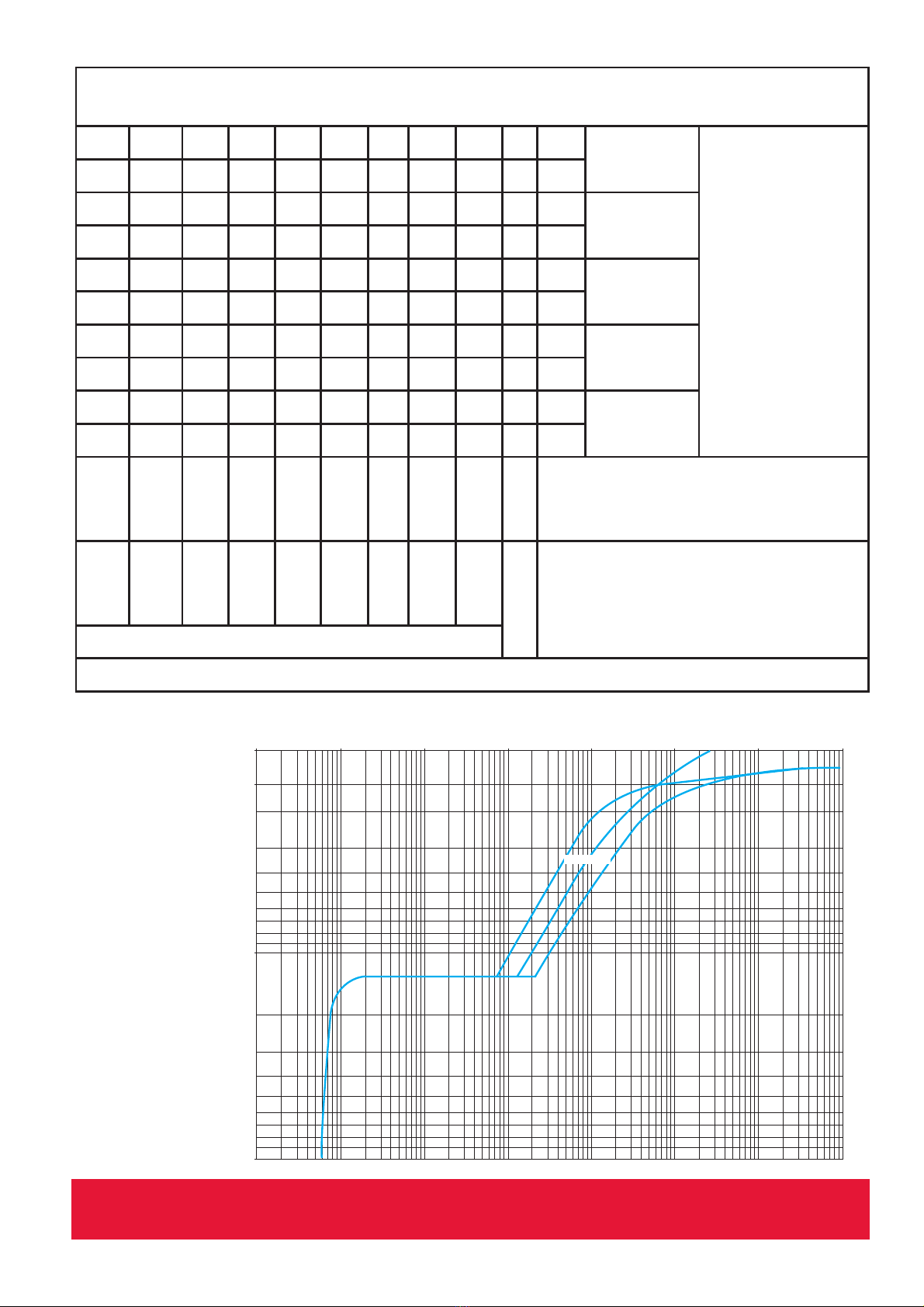
• Set the tripping dial to the corresponding motor voltage (See chart)
• Overcurrent and residual current protective devices must be provided
by the customer, according to standards, the cable length between the
protective devices and the motor protection plug must not exceed 3m
Notes
• Never use oils, grease or any kind of solvents, these substances have
negative effects on the plastics rigidity
Disposal
This product or parts of it must be disposed of in an environmentally sound way:
5SETHEPUBLICORPRIVATEWASTECOLLECTIONSERVICE)FTHISISNOTPOSSIBLEPLEASECONTACT
YOUR./,4!DEALER

Technical Data
Table 2
Housing material: Polycarbonate
Protection class: )0
#%%! #%%!
Length 285 mm MMAND
aprox. 1m
CORD(2.&
5G2,5mm²
Width: 90 mm
Height: MM
Weight Ca. 950 g Ca. 1500 g
Mechanical service life: 1 x 10⁵ switching cycles
Nominal operating voltage: n6!#
Nominal operating current: -IN!-AX!
Perm. power frequency: (Z
Temperature range: x#
-AGNETICTRIPPING Yes
Temp. compensation: Yes
Trip time: 3EElGURE
-AXBACKUPFUSERATING See table 1
Cable entry: M 32 x 1,5
Clamping range: 8 – 18 mm
#ROSSSECTIONALAREAOFMAINCONDUCTOR Single core: Fine stranded:
XxMMß XxMMß
XxMMß XxMMß
!PPROVALFORMOTORPROTECTIONSWITCH !4%88
#ROSSSECTIONALAREAOF
main conductor:
Single core: Fine stranded:
XxMMß XxMMß
XxMMß XxMMß
/NLYAPPLIESTOTHEMOTORPROTECTIONSWITCHTHENOMINALVOLTAGEISDElNEDBYTHE
plug attachment and the phase sequence unit.
Technical data subject to change

Installation
• Connection according to circuit diagram
• Frequent opening / closing of the switchgear should be avoided
• %XTERNALDAMAGEANDDEFECTIVESEALINGELEMENTSWILLINVALIDATETHE)0DEGREEOF
protection
• 7HENSCREWINGTHELIDBACKONITMUSTBEENSUREDTHATTHEHOUSINGHALVESlT
exactly one above the other and are not tightened all at once
Circuit Diagram
3(
RSWLRQDO
/ / / 1
RSWLRQDO
/
/
/
SKDVHVHTXHQFHLQGLFDWRU
/ / / 1 3(
SKDVHLQYHUWHU
RSWLRQDO
,! ,!,!
/
/
RSHUDWLQJLQGLFDWRU
Figure 2
Intended use
The electrical equipment is used to protect the electric motors through thermal and
electromagnetic tripping. This electrical equipment was developed, designed and built
exclusively for industrial and commercial use. Private use is excluded.
Intended use also includes compliance with the operating and operating instructions
SPECIlEDBYTHEMANUFACTURERASWELLASTHEMAINTENANCEANDREPAIRCONDITIONS
4HE./,4!PUSHBUTTON)0MAYSWITCHMOTORSINTHE!4%8AREAPROVIDEDTHEPUSH
BUTTONITSELFISOUTSIDETHE!4%8ZONE
4HE./,4!PUSHBUTTON)0WASSPECIALLYDEVELOPEDFORUSEINAREASOFAPPLICATION
WITHINCREASEDPROTECTIONREQUIREMENTSEGINlREBRIGADESANDDISASTERCONTROL4HE
push button design guarantees maximum tightness with absolutely reliable switching
behavior.

Operation
• 4HE)0MOTORPROTECTIONPLUGMAYONLYBEUSEDWITHACOUPLINGORSOCKETTHATIS
ALSO)0CERTIlED
• $EGREEOFPROTECTION)0ISONLYACHIEVEDWHENTHELOCKINGRINGISLOCKED
• Constant immersion is to be avoided
• When unplugged, the motor protection plug has no IP protection and should be
stored with the plug facing down
Push button for manual on / off switching
/&&REDBUTTONÑÑ
/.BLACKBUTTONÑÑ
&ORINTEGRATEDROTATINGlELDCONTROLANDPHASEINVERTER
• 2EDlELDLIGHTSUPORmASHESINCORRECTPHASESEQUENCE
• The direction of rotation is changed by gently pressing and turning the pole pins in
the plug insert
• !FTERANOVERCURRENTTRIPTHEMOTORPROTECTIONSWITCHCANONLYBESWITCHEDON
again after the bimetals have cooled down. This can take a few minutes.
/PTIONALROTATINGlELDMONITORING
• )FTHEPHASESINTHEMAINSINPUTARESWAPPEDWRONGROTATINGlELDTHE,%$OFTHE
ROTATINGlELDCONTROLmASHES4HEELECTRONICSPREVENTTHEMOTORPROTECTIONSWITCH
from being switched on via the undervoltage coil. This prevents the connected
motor from starting in the wrong direction of rotation.
• #ORRECTIVEACTION3WITCHOVERTHEROTATINGlELDBYTURNINGTHEPHASEINVERTERINTHE
plug adapter.

Table 1
0,001
0,1
1
10
100
0,01
1 1,5 10 100
1000
10 000
3
2
1
Time (s)
x the setting current (Ir)
1 3 poles from cold state
2 2 poles from cold state
3 3 poles from hot state
Tripping Characteristics
Figure 1
&USE2ATINGOF'6-%
Motor Protection device '6-%
01
to
06
08 10 14 16 20 21
&
22
32
3IZE ! 0,1
to
1,6
2,5 4 6,3 10 14 18 23
&
25
32
Backup fuse
(only necessa
ry when Icc >
Breaking capa
CITY)CUSEE)%#
230/240 V aM ! 80 80
gG ! 100 100
400/415 V aM ! 63 63 80 80
gG ! 80 80 100 100
440 V aM ! 50 50 50 50 63 63
gG ! 63 63 63 63 80 80
500 V aM ! 50 50 50 50 50 50
gG ! 63 63 63 63 63 63
690 V aM ! 16 25 32 32 40 40 40 40
gG ! 20 32 40 40 50 50 50 50
K!

EU Declaration of Conformity
We hereby declare that the Nolta – Drucktaster specified below will, due to its design and construction,
comply with the relevant regulations listed.
Product Designation Nolta – Drucktaster
Manufacturer Nolta GmbH
Industriestr. 8
D-35091 Cölbe
EU directives / Harmonized standards /
national techn. Standards - Specifications
Low Voltage Directive 2014/35/EU
EN 61010-1:2010 Safety requirements for electrical equipment for measurement, control
and laboratory use – Part 1: General requirements (IEC 61010-
1:2010+Cor:2011)
EN 82079-1:2012 Preparation of instructions for use – Structuring, content and detailed
requirements (IEC 82079-1:2012)
Electromagnetic Compatibility Directive – Directive 2014/30/EU
EN 61000-6-2:2005 + AC:2005 Electromagnetic compatibility (EMC) – Part 6-2: Generic standards –
Immunity for industrial environments (IEC 61000-6-2:2005)
EN 61000-6-4:2006 + A1:2011 Electromagnetic compatibility (EMC) – Part 6-4: Generic standards –
Emission standard for industrial environments (IEC 61000-6-
4:2006+A1:2010)
EN 60204-1:2006
EN 61439-1:2011
Referring to Chapter 4.4.2 Electromagneitc compatibility (EMC)
Referring to Appendix J
Restriction of use of certain hazardous substances in electrical and
electronic equipment (RoHS) – Directive 2011/65/EU & 2015/863/EU
Authorized representative
Name and address
David Loechelt
Nolta GmbH
Industriestr. 8
D-35091 Cölbe
We confirm that a CE mark according to the European directives is affixed to the above mentioned Nolta -
Drucktaster.
25.02.2019 ................................................ ................................................
Date CEO Head of Quality Management
Dr. Ing J. Knake D. Loechelt

EU-Konformitätserklärung
Hiermit erklären wir, dass der nachfolgend bezeichnete Nolta – Drucktaster aufgrund seiner Konzipierung
und Bauart den aufgeführten einschlägigen Bestimmungen entsprechen wird.
Bezeichnung Nolta – Drucktaster
Hersteller Nolta GmbH
Industriestr. 8
35091 Cölbe
EU-Richtlinien / Harmonisierte Normen /
nationale techn. Normen - Spezifikationen
Niederspannungsrichtlinie 2014/35/EU
EN 61010-1:2010 Sicherheitsbestimmungen für elektrische Mess-, Steuer-, Regel-, und
Laborgeräte – Teil 1: Allgemeine Anforderungen (IEC 61010-
1:2010+Cor:2011)
EN 82079-1:2012 Erstellen von Gebrauchsanleitungen – Gliederung, Inhalt und Darstellung
– Teil 1: Allgemeine Grundsätze und ausführliche Anforderungen (IEC
82079-1:2012)
Richtlinie elektromagnetische Verträglichkeit – Richtlinie 2014/30/EU
EN 61000-6-2:2005 + AC:2005 Elektromagnetische Verträglichkeit (EMV) – Teil 6-2: Fachgrundnorm –
Störfestigkeit für Industriebereiche (IEC 61000-6-2:2005)
EN 61000-6-4:2006 + A1:2011 Elektromagnetische Verträglichkeit (EMV) – Teil 6-4: Fachgrundnorm –
Störaussendung für Industriebereiche (IEC 61000-6-4:2006+A1:2010)
EN 60204-1:2006
EN 61439-1:2011
Bezogen auf Kapitel 4.4.2 Elektromagnetische Verträglichkeit (EMV)
Bezogen auf Anhang J
Beschränkung der Verwendung bestimmter gefährlicher Stoffe in Elektro-
und Elektronikgeräten (RoHS) – Richtlinie 2011/65/EU & 2015/863/EU
Dokumentationsbevollmächtigter
Name und Anschrift
David Loechelt
Nolta GmbH
Industriestr. 8
35091 Cölbe
Wir bestätigen, dass an dem oben genannten Nolta – Drucktaster ein CE-Zeichen, entsprechend den
Europäischen Richtlinien, angebracht wird.
25.02.2019 ................................................ ................................................
Datum Geschäftsführer Leiter Qualitätsmanagement
Dr. Ing J. Knake D. Loechelt

0,001
0,1
1
10
100
0,01
1 1,5 10 100
1000
10 000
3
2
1
Zeit (s)
x-fache des Einstellstroms (Ir)
1 3-polige Belastung aus kaltem Zustand
2 2-polige Belastung aus kaltem Zustand
3 3-polige Belastung aus warmem Zustand
Auslösekennlinie
!BBILDUNG
Tabelle 2
!USSCHALTVERMÈGENDER'ER¹TE'6-%
-OTORSCHUTZSCHALTERTYP '6-%
01
bis
06
08 10 14 16 20
21
&
22
32
"AUGRÈE
!
0,1
bis
1,6
2,5 4 6,3 10 14 18
23
&
25
32
Vorsicherung
(nur erforderlich,
WENN)CC!US
schaltvermögen
)CUGEM¹)%#
230/240 V aM !80 80
gG !100 100
400/415 V aM !63 63 80 80
gG !80 80 100 100
440 V aM ! 50 50 50 50 63 63
gG ! 63 63 63 63 80 80
500 V aM ! 50 50 50 50 50 50
gG ! 63 63 63 63 63 63
690 V aM ! 16 25 32 32 40 40 40 40
gG ! 20 32 40 40 50 50 50 50
K!
(1) In % von Icu.

Bedienung
• $ER-OTORSCHUTZSTECKER)0DARFNURMITEINEREBENFALLS)0GEPRÍFTEN+UPPLUNG
oder Steckdose verwendet werden
• $IE3CHUTZART)0WIRDNURDANNERREICHTWENNDER6ERSCHLUSSRINGVERRIEGELTIST
• 3T¹NDIGESUNTERTAUCHENISTZUVERMEIDEN
• )MAUSGESTECKTEN:USTANDHATDER-OTORSCHUTZSTECKERKEINEN)03CHUTZUNDSOLLTE
MITu3TECKERNACHUNTENhGELAGERTWERDEN
Drucktaster für manuelle Ein-/Aus-Schaltung
!532OTE4ASTEÑÑ
%).3CHWARZE4ASTEÑÑ
Für integrierte Drehfeldkontrolle und Phasenwender
• 2OTES&ELDLEUCHTETODERBLINKT0HASENFOLGEFALSCH
• $REHRICHTUNGS¹NDERUNGWIRDDURCHLEICHTES%INDRÍCKENUND$REHENDER0OLSTIFTEIM
3TECKEREINSATZERREICHT
• .ACHEINER´BERSTROMAUSLÈSUNGL¹SSTSICHDER-OTORSCHUTZSCHALTERERSTNACH!B
KÍHLUNGDER"IMETALLEWIEDEREINSCHALTEN$IESKANNEINIGE-INUTENDAUERN
Optional: Drehfeldüberwachung
• 3OLLTENIM.ETZEINGANGDIE0HASENVERTAUSCHTSEINFALSCHES$REHFELDLEUCHTETDIE
'LIMMLAMPEBLINKTDIE,%$DER$REHFELDKONTROLLE$IE%LEKTRONIKVERHINDERTÍBER
DIE5NTERSPANNUNGSSPULEDAS%INSCHALTENDES-OTORSCHUTZSCHALTERS$ADURCHWIRD
VERHINDERTDASSDERANGESCHLOSSENE-OTORINFALSCHER$REHRICHTUNGANL¹UFT
• Fehlerbehebung: Das Drehfeld durch Verdrehen des Phasenwenders im Steckervor
SATZUMSCHALTEN
Schaltplan
!BBILDUNG
3(
RSWLRQDO
/ / / 1
RSWLRQDO
/
/
/
'UHKIHOGNRQWUROOH
/ / / 1 3(
3KDVHQZHQGHU
RSWLRQDO
,! ,!,!
/
/
%HWULHEVDQ]HLJH

Installation
$ASELEKTR"ETRIEBSMITTELDIENTZUM3CHUTZDERELEKTRISCHEN-OTORENDURCHTHERMISCHE
UNDELEKTROMAGNETISCHE!USLÈSUNG$IESESELEKTR"ETRIEBSMITTELWURDEAUSSCHLIELICH
FÍRDIEINDUSTRIELLEUNDGEWERBLICHE.UTZUNGENTWICKELTKONSTRUIERTUNDGEBAUT%INE
PRIVATE.UTZUNGWIRDAUSGESCHLOSSEN
:URBESTIMMUNGSGEM¹EN6ERWENDUNGGEHÈRTAUCHDIE%INHALTUNGDERVOM(ERSTELLER
VORGESCHRIEBENEN"EDIENUNGSUND"ETRIEBSANWEISUNGENSOWIEDIE7ARTUNGSUND)N
standhaltungsbedingungen.
$ER./,4!$RUCKTASTER)0DARF-OTORENIM!4%8"EREICHSCHALTENSOFERNSICHDER
$RUCKTASTERSELBSTAUERHALBDER!4%8:ONEBElNDET
$ER./,4!$RUCKTASTER)0WURDESPEZIELLFÍRDEN%INSATZIN!NWENDUNGSGEBIETENMIT
ERHÈHTEN3CHUTZANFORDERUNGENENTWICKELTZ"BEI&EUERWEHRENUND+ATASTROPHEN
SCHUTZ$IE$RUCKTASTERAUSFÍHRUNGGARANTIERTHÈCHSTE$ICHTIGKEITBEIABSOLUTZUVERL¹SSI
gem Schaltverhalten.
Bestimmungsgemäßer Gebrauch
• %LEKTRISCHER!NSCHLUSSUND&EHLERBESEITIGUNGNURDURCHENTSPRECHENDZUGELASSENE
%LEKTROFACHKRAFT
• 6ORJEDEM%INGRIFFISTDER-OTORSCHUTZSTECKERVOM.ETZZUTRENNEN
• Die maximale Vorsicherung muss bauseitig sichergestellt sein (siehe Tabelle 2)
• Motornennstrom ININNERHALBDES!USLÈSEBEREICHESEINSTELLEN
• -OTORANSCHLUSSGEM¹!NSCHLUSSBILD
• (¹UlGES¯FFNEN3CHLIEENDES3CHALTGER¹TESISTZUVERMEIDEN
• $URCH¹UERE"ESCH¹DIGUNGENUNDDEFEKTEN$ICHTUNGSELEMENTENERLISCHTDIE
3CHUTZART)0
• "EIM7IEDERVERSCHRAUBENISTDARAUFZUACHTENDASSDIE'EH¹USEH¹LFTENPASSGENAU
ÍBEREINANDERSITZENUNDNICHTAUFEINMALu%NDFESThANGEZOGENWERDEN
• +EINE¯LE&ETTEODER,ÈSUNGSMITTELVERWENDENDIESE3UBSTANZENBEEINTR¹CHTIGEN
DIE3TABILIT¹TDES+UNSTSTOFFES

Technische Daten
'EH¹USEMATERIAL Polycarbonat
3CHUTZKLASSE )0
#%%! #%%!
,¹NGE 285 mm MMUNDCAM
:ULEITUNG(2.&
5G2,5mm²
Breite: 90 mm
Höhe: MM
Gewicht Ca. 950 g Ca. 1500 g
Mech. Lebensdauer: 1 x 10⁵ Schaltspiele
Nennbetriebsspannung: n6!#
Nennbetriebsstrom: -IN!-AX!
:UL.ETZFREQUENZ (Z
Temperaturbereich: x#
-AGN!USLÈSUNG Ja
4EMP+OMPENSATION Ja
!USLÈSEZEIT 3IEHE!BBILDUNG
Max. Vorsicherung: Siehe Tabelle 2
+ABELEINFÍHRUNG M 32 x 1,5
Klemmbereich: 8 – 18 mm
!NSCHLUSSQUERSCHNITTEDER(AUPTLEITER %INDR¹HTIG &EINDR¹HTIG
XxMMß XxMMß
XxMMß XxMMß
:ULASSUNGDES-OTORSCHUTZSCHALTERS !4%88
'ILTNURFÍRDEN-OTORSCHUTZSCHALTER.ENNSPANNUNGWIRDDURCH3TECKERVORSATZ
und Drehfeldkontrolle festgelegt
Technische Änderungen vorbehalten
Tabelle 1

GEFAHR
Tod oder ernsthafte Personenschäden
• %LEKTRISCHER!NSCHLUSSUND&EHLERBESEITIGUNGNURDURCHENTSPRECHEND
ZUGELASSENE%LEKTROFACHKRAFT
• 6ORJEDEM%INGRIFFISTDER-OTORSCHUTZSTECKERVOM.ETZZUTRENNEN
• $ER-OTORSCHUTZSTECKER)0DARFNURMITEINEREBENFALLS)0GEPRÍF
ten Kupplung oder Steckdose verwendet werden!
• $IE3CHUTZART)0WIRDNURDANNERREICHTWENNDER6ERSCHLUSSRING
verriegelt ist!
• (¹UlGES¯FFNEN3CHLIEENDES3CHALTGER¹TESISTZUVERMEIDENÐ
• $URCH¹UERE"ESCH¹DIGUNGENUNDDEFEKTEN$ICHTUNGSELEMENTEN
ERLISCHTDIE3CHUTZART)0Ð
• 3T¹NDIGESUNTERTAUCHENISTZUVERMEIDENÐ
• )MAUSGESTECKTEN:USTANDHATDER-OTORSCHUTZSTECKERKEINEN)0
3CHUTZUNDSOLLTEMITu3TECKERNACHUNTENhGELAGERTWERDENÐ
• "EIM7IEDERVERSCHRAUBENISTDARAUFZUACHTENDASSDIE'EH¹USE
H¹LFTENPASSGENAUÍBEREINANDERSITZENUNDNICHTAUFEINMALu%ND
FESThANGEZOGENWERDENÐ
Vorsicht
• !USLÈSESTROMDES-OTORSCHUTZSCHALTERSAUFDEN-OTORNENNSTROM
einstellen
• ´BERSTROMUND&EHLERSTROMSCHUTZEINRICHTUNGENMÍSSENBAUSEITIG
SICHERGESTELLTSEINUMEINENNORMGERECHTEN"ETRIEBZUGEW¹HRLEISTEN
DARFDIE,EITUNGSL¹NGEZWISCHENDEN3CHUTZORGANENUNDDEM-OTOR
SCHUTZSTECKERMNICHTÍBERSCHREITEN
Hinweise
• +EINE¯LE&ETTEODER,ÈSUNGSMITTELVERWENDENDIESE3UBSTANZEN
BEEINTR¹CHTIGENDIE3TABILIT¹TDES+UNSTSTOFFES
Warnhinweise
Entsorgung:
$IESES0RODUKTSOWIE4EILEDAVONMÍSSENUMWELTGERECHTENTSORGTWERDEN
.UTZEN3IEDIEÈFFENTLICHENODERPRIVATEN%NTSORGUNGSGESELLSCHAFTEN
)STDASNICHTMÈGLICHWENDEN3IESICHBITTEAN)HREN./,4!(¹NDLER
Entsorgung

Allgemeine Informationen
Bitte lesen Sie diese Betriebsanleitung bevor Sie das Produkt installieren
und in Betrieb nehmen. Beachten Sie alle Sicherheitshinweise, örtliche
Vorschriften und technischen Bestimmungen.
$IE)NSTALLATIONDARFNURDURCHEINEENTSPRECHENDQUALIlZIERTE%LEKTRO
fachkraft erfolgen.
$IESES0RODUKTDARFNURZUDEMBESTIMMUNGSGEM¹EN'EBRAUCHGEM¹
DIESER"ETRIEBSANLEITUNGEINGESETZTWERDEN
$IEFOLGENDEN3YMBOLE3ICHERHEITSHINWEISEUND(INWEISEWERDENINDIESER"ETRIEBS
und Montageanweisung verwendet:
Sicherheitshinweise Hinweise
$IE3ICHERHEITSHINWEISESINDFOLGENDERMA
ENAUFGEBAUT
GEFAHR
+ENNZEICHNETEINE'EFAHREN
situation, die, wenn sie nicht
VERMIEDENWIRDZUERNST
HAFTEN0ERSONENSCH¹DENODER
4ODESF¹LLENFÍHRENWIRD
%INBLAUERODERGRAUER+REIS
MITEINEMWEIENGRAlSCHEN
Symbol weist darauf hin, dass
EINE-ANAHMEERGRIFFEN
werden muss.
%INROTERODERGRAUER+REIS
MITEINEMDIAGONALVER
laufenden Balken (ggf. mit
EINEMSCHWARZENGRAlSCHEN
Symbol) weist darauf hin,
dass eine Handlung nicht
AUSGEFÍHRTWERDENDARFODER
gestoppt werden muss.
%IN.ICHTBEACHTENDIESER3I
CHERHEITSHINWEISEKANN&EHL
FUNKTIONENODER3ACHSCH¹DEN
ZUR&OLGEHABEN
Warnung
+ENNZEICHNETEINE'EFAHREN
situation, die, wenn sie nicht
VERMIEDENWIRDZUERNST
HAFTEN0ERSONENSCH¹DENODER
4ODESF¹LLENFÍHRENKANN
Vorsicht
+ENNZEICHNETEINE'EFAHREN
situation, die, wenn sie nicht
VERMIEDENWIRDZULEICHTEN
ODERMITTELSCHWEREN0ERSO
NENSCH¹DENFÍHRENKANN
Signalwort
Beschreibung der Gefahr
&OLGENBEI.ICHTBEACHTUNGDES7ARNHIN
weises.
-ANAHMENZUM6ERMEIDENDER'EFAHR

Drucktaster IP67
Betriebsanleitung und
Sicherheitshinweise
11 8011/ 02.2021
Nolta GmbH Tel. +49(0)6421/9859 0
Industriestr. 8 Fax +49(0)6421/9859 28
35091 Cölbe www.nolta.de
Germany [email protected]
DE
Table of contents
Other Nolta Medical Equipment manuals