Operation
Push button for manual on / off switching
/&&REDBUTTONÑÑ
/.BLACKBUTTONÑÑ
&ORINTEGRATEDROTATINGlELDCONTROLANDPHASEINVERTER
• 2EDlELDLIGHTSUPORmASHESINCORRECTPHASESEQUENCE
• The direction of rotation is changed by gently pressing and turning the pole pins in
the plug insert.
• !FTERANOVERCURRENTTRIPTHEMOTORPROTECTIONSWITCHCANONLYBESWITCHEDON
AGAINAFTERTHEBIMETALSHAVECOOLEDDOWN4HISCANTAKEAFEWMINUTES
/PTIONALROTATINGlELDMONITORING
• )FTHEPHASESINTHEMAINSINPUTARESWAPPEDWRONGROTATINGlELDTHE,%$OFTHE
ROTATINGlELDCONTROLmASHES
• The electronics prevent the motor protection switch from being switched on via the
undervoltage coil. This prevents the connected motor from starting in the wrong
direction of rotation
• #ORRECTIVEACTION3WITCHOVERTHEROTATINGlELDBYTURNINGTHEPHASEINVERTERINTHE
plug adapter
Installation
• %LECTRICALCONNECTIONANDTROUBLESHOOTINGMAYONLYBECARRIEDOUTBYAQUALIlED
electrician
• Before any intervention, the motor protection plug must be disconnected from the
mains
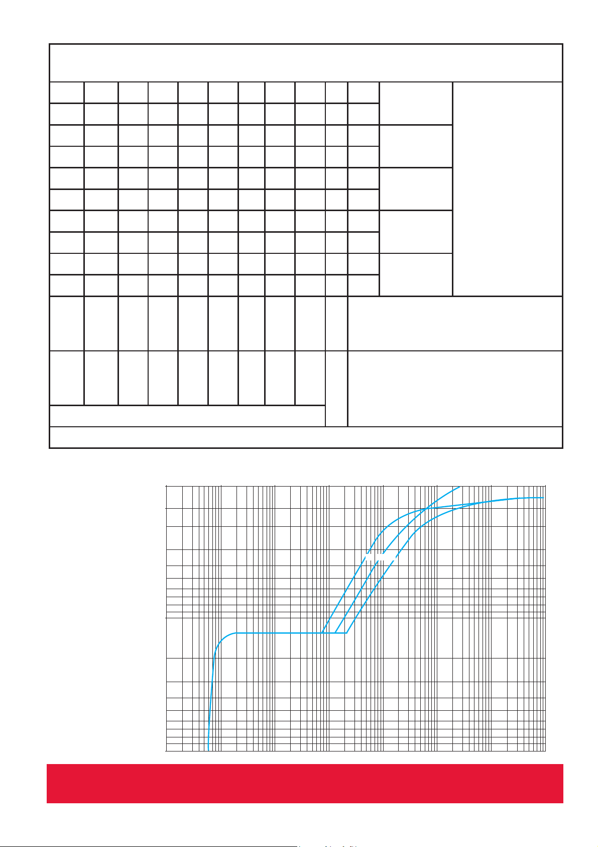
• The maximum backup fuse must be ensured on site (see table 1)
• Set the rated motor current INwithin the tripping range
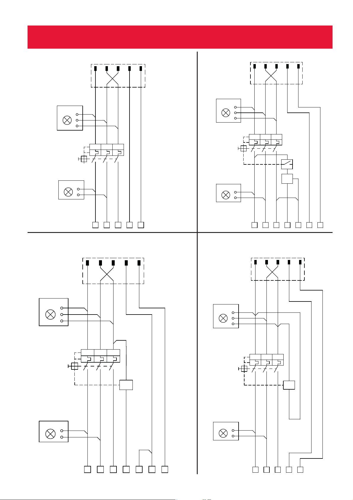
• Motor connection according to the connection diagram
• Do not use oils, greases or solvents, these substances impair the stability of the
plastic
Intended use
The electrical equipment is used to protect the electric motors through thermal and
electromagnetic release. This electrical equipment was developed, designed and built
exclusively for industrial and commercial use. Private use is excluded.
Intended use also includes compliance with the operating instructions prescribed by the
manufacturer as well as the maintenance and repair conditions.
4HE./,4!PUSHBUTTONMAYSWITCHMOTORSIN!4%8ZONESPROVIDEDTHEPUSHBUTTON
ITSELFISOUTSIDETHE!4%8ZONE