NookBox Vesta P119015 User manual

1NookBox Installation Guide Repeater
NookBox Repeater
(P119015 / E6309684)
Installation Guide
2NookBox Installation Guide Repeater
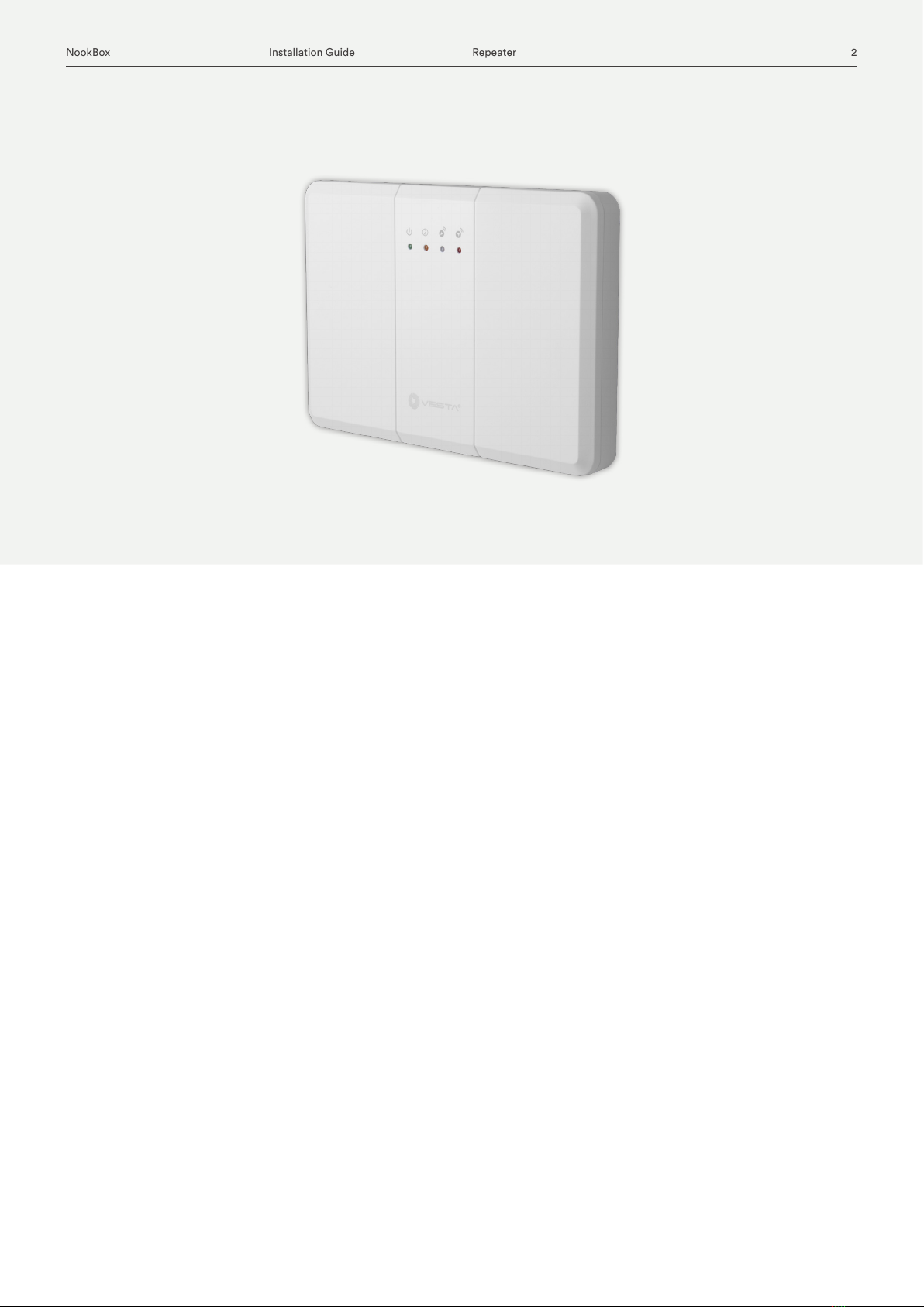
The Repeater is designed to increase the eectiveness and versatility of the alarm system. It is
a device that makes your system more powerful by increasing the maximum possible distance
between the Main Unit (Control Panel) and the Devices.
NookBox Repeater
(P119015 / E6309684)
3NookBox Installation Guide Repeater
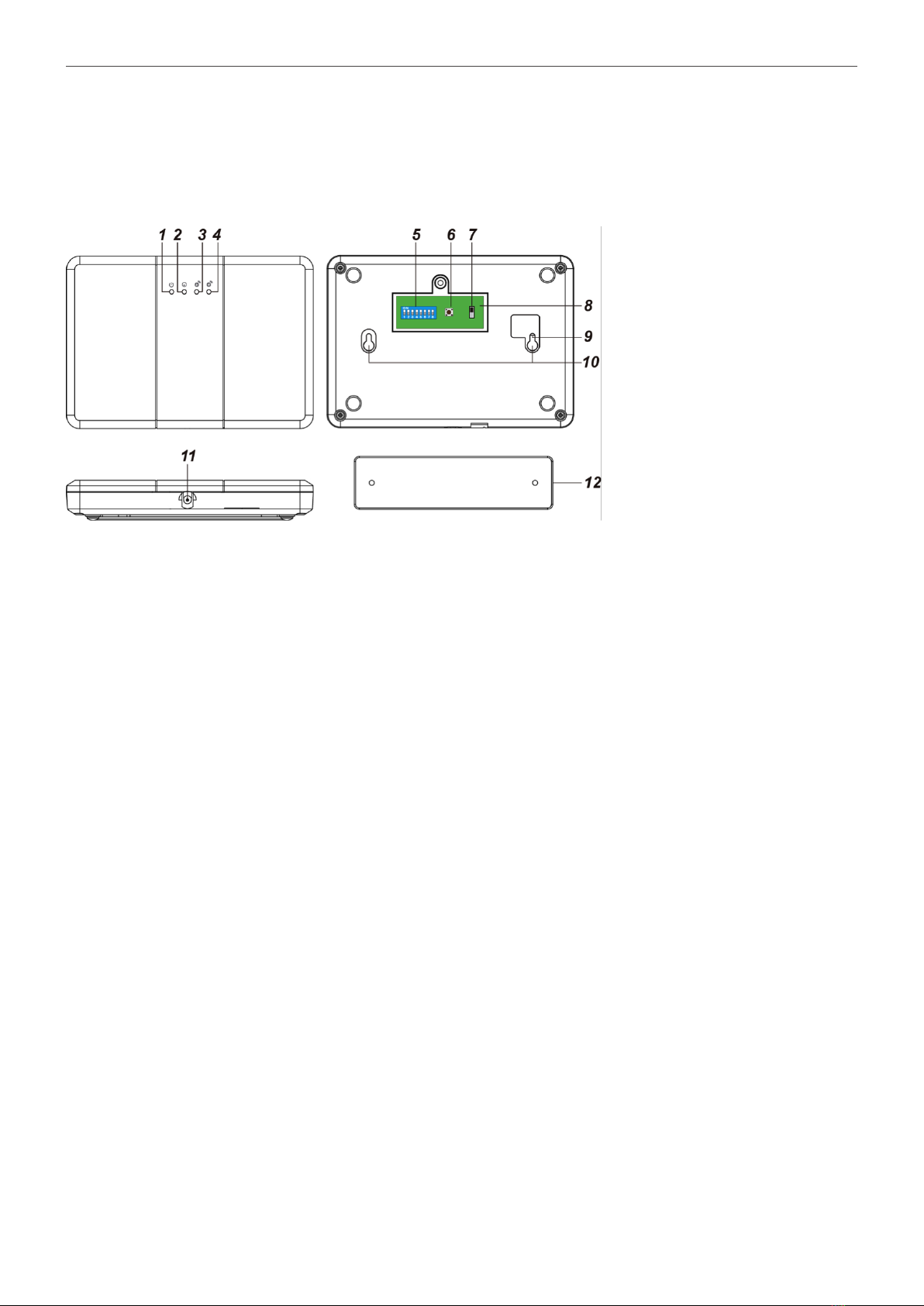
Identifying the parts
1. Power LED (Green)
On – Powered by a Power Adapter or Rechargeable Battery
Flash – Rechargeable Battery low on power
2. Mode LED (Yellow)
On – The Repeater is in Learning Mode (Panel) or Clear Mode
Flash (1 ash every second) – The Repeater is in Walk Test Mode
Slow Flash (1 ash every 2 seconds) – The Repeater is in Learning Mode (Device)
3. Transmission: Receive LED (Blue)
The Blue LED lights up when the Repeater receives a signal transmission
4. Transmission: Transmit LED (Red)
The Red LED lights up when the Repeater transmits a signal.
5. Functional Switch Block
6. Test Button
7. Power Switch
8. Removable Cover
9. Tamper Switch
10.Mounting Hole
11. DC power jack
12.Mounting Bracket

4NookBox Installation Guide Repeater
Power Supply
A Power Adapter is required to connect to a wall power outlet. Be sure only to use an adapter with the appropriate AC voltage
rating to prevent component damage. A DC 12V 1A output Power Adapter is generally used to power the Repeater.
Power Adapter Application:
To connect the Power Adapter:
Step 1 Locate the Power Adapter and plug into the DC power jack.
Step 2 Plug the Power Adapter to a wall power outlet.
Step 3 The Repeater will sound a Long beep and the Green LED will light up.
AC Failure/AC Restore:
The Repeater will send an AC Failure signal to the Control Panel when the Power Adapter is unplugged for 30-60 seconds.
When the Power Adapter is plugged in again for 30-60 seconds, the Repeater will send an AC Restore signal to the Control Panel.
Rechargeable Battery:
In addition to the adapter, there is a rechargeable battery inside the Repeater, which serves as a back-up power in case of a power failure.
When the Power Adapter is plugged into the DC power jack, slide the Power Switch to the ON position so the Power Adapter supplies power
to the Repeater and at the same time recharges the battery. It takes approximately 72 hours to fully charge the battery.
When the Power Adapter is unplugged, the Repeater will be powered by the rechargeable battery.
The Repeater can detect the battery voltage. When the battery voltage is low, the Green LED will ash to indicate low battery status.
5NookBox Installation Guide Repeater
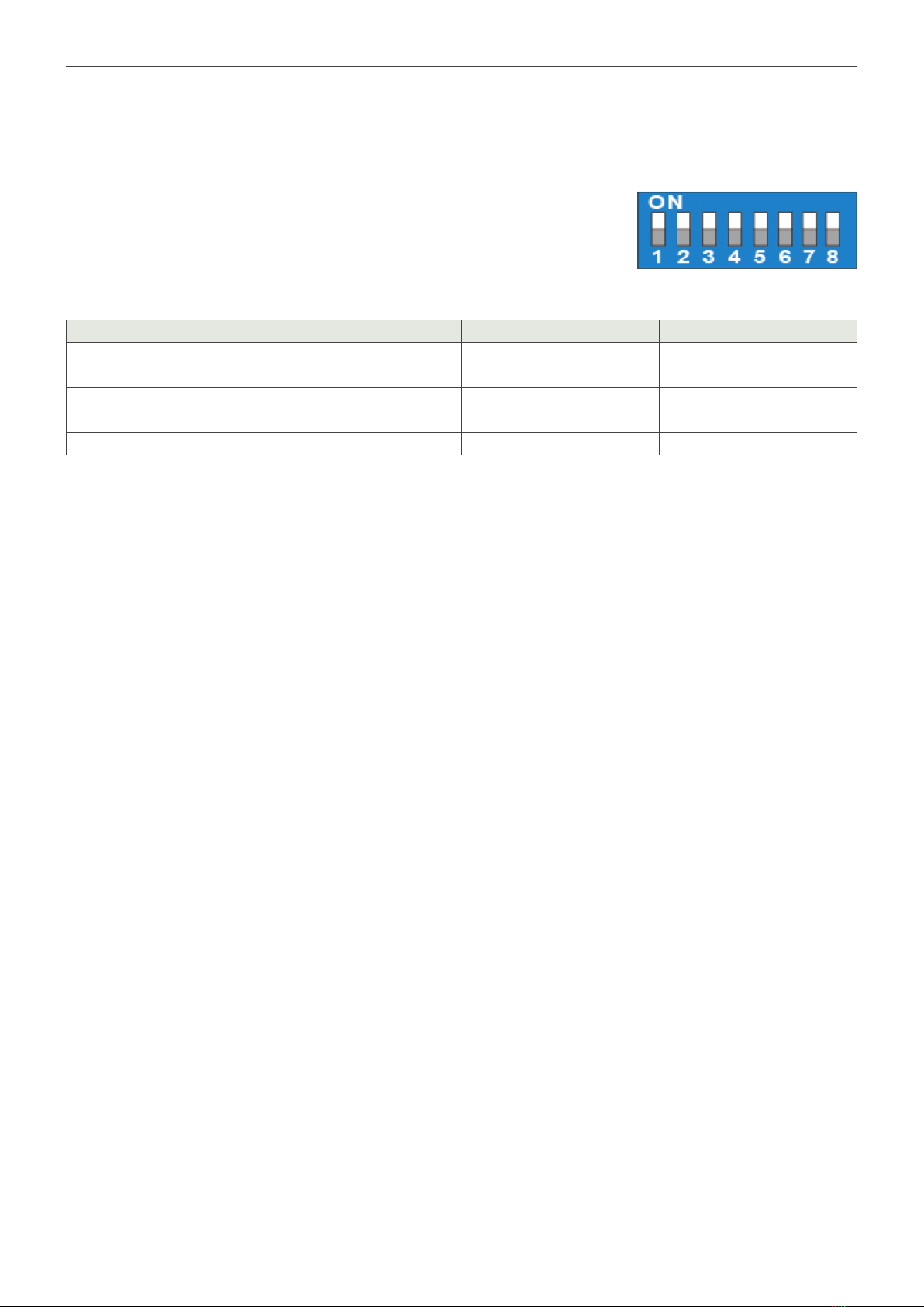
Functional Switch Block
The Functional Switch Block determines which Mode the Repeater is in.
A switch in the up position indicates the (ON) Mode.
Likewise, a switch in the down position indicates the (OFF) Mode.
DIP Switches 5, 6 and 7 are reserved.
The DIP Switch settings are only valid when the Repeater is powered. For example, DIP Switch 3 is slid to the On position when the
Repeater is turned o. When the Repeater is turned on, it will NOT enter Clear Mode. However, if the DIP Switch 3 is slid to the O
position rst, followed by sliding to the On position, the Repeater will enter Clear Mode.
Supervisory Signal
• After being learnt in to the Control Panel, the Repeater will automatically transmit Supervisory Signals every 30 to 50 minutes.
• If the Control Panel has not received the signal from the Repeater for a preset period of time, the Control Panel will indicate it on
its display to show that the Repeater is experiencing an out-of-signal problem.
How to mount the Repeater
The Repeater can be placed on the table, mounted on the wall or wherever desired. Follow the steps below to mount the Repeater:
Step 1 Using the holes of the Mounting Bracket as a template, drill holes into the mounting surface.
Step 2 Insert the wall plugs if xing into plaster or brick. Screw the Mounting Bracket to the wall.
Step 3 Hook the Repeater onto the Wall Mounting Bracket (with the Mounting Holes of the Repeater).
Tamper Protection
• The Tamper Switch is in normal operating position (Tamper Closed) when the Repeater is hooked onto the Wall Mounting Bracket.
Tamper violation happens when the Repeater is removed from the hook where Tamper Switch is released (Tamper Opened).
• The tamper protection function can be disabled when DIP Switch 8 is slid to the ON position. It is enabled when DIP Switch 8 is slid
to the OFF position.
Function ON OFF
DIP Switch 1 Learn Device Learning mode (Device) Normal Mode
DIP Switch 2 Range or Walk Test Walk Test Mode Normal Mode
DIP Switch 3 Factory Reset Clear Mode Normal Mode
DIP Switch 4 Learn into Control Panel Learning mode (Panel) Normal Mode
DIP Switch 8 Tamper Function Disable Normal Mode (Enabled)

6NookBox Installation Guide Repeater
Learn into Control Panel
Step 1 To learn the Repeater into the Control Panel, slide DIP Switch 4 to the On position under Normal Mode.
The Repeater will emit 1 long beep and the Yellow LED will turn on.
Step 2 Put the Control Panel into Learning Mode (please refer to the Control Panel manual).
Step 3 Press the Test button. The Repeater will transmit a Test Code to the Control Panel as the Red LED lights up and the
Repeater emits 1 beep.
Step 4 If the Repeater receives an acknowledge signal from the Control Panel within 60 seconds, Learning is successful.
The Blue LED will light up for 1 second as the Repeater emits 1 long beep.
If the Repeater fails to receive an acknowledge signal from the Control Panel within 60 seconds,
learning has failed and is indicated by the Yellow LED flashing 3 times. Please repeat step 3-4 again.
Step 5 Slide DIP Switch 4 to the Off position. The Repeater will emit 1 long beep and the Yellow LED will turn off as the
Repeater returns to Normal Mode.
Learning Repeater into Repeater
If Repeater A is learning into Repeater B:
Step 1 Putting Repeater B into learning mode: Under Normal Mode, slide DIP Switch 1 of Repeater B to the On position.
Repeater B will emit 1 long beep and the Yellow LED will flash slowly (1 flash every 2 seconds).
Step 2 Press the Test Button on Repeater A to send a learn code. Repeater A will emit 1 beep and the Red LED will turn on.
If Repeater B receives the learn code from Repeater A, it will emit 1 long beep and the Blue LED will light up for 1 second
to indicate successful learning.
If Repeater B receives the learn code from Repeater A and Repeater A was already learnt, Repeater B will emit 2 beeps and
the Blue LED will light up for 1 second.
<NOTE>
• Please do not cross-learn the Repeaters, e.g. Learning Repeater A into Repeater B and learning Repeater B into Repeater A.
• All repeaters will have to be learnt into the Control Panel.
Step 3 When the learning is complete, slide DIP Switch 1 of Repeater B to the Off position. Repeater B will emit 1 long beep
and the Yellow LED will turn off as Repeater B returns to Normal Mode.
Learning Device into Repeater
Step 1 Under Normal Mode, slide DIP Switch 1 to the On position. The Repeater will emit 1 long beep and the Yellow LED
will ash slowly (1 ash every 2 seconds).
Step 2 Please refer to the device manuals on how to send learn code from the devices
(usually a Test or Learn button is pressed on the devices).
If the Repeater receives a learn code from a new device, it will emit 1 long beep and the Blue LED will light up for 1 second
to indicate successful learning.
If the Repeater receives a learn code from a device already learnt into the Repeater, it will emit 2 beeps and the Blue LED
will light up for 1 second.
A maximum of 60 devices can be learnt into the Repeater. If the user attempts to learn in a 61st device,
the Repeater will emit 4 beeps.
<NOTE>
• If multiple repeaters are used, please only learn devices into the Repeater(s) closest to the operation areas of the devices.
• All the devices learnt into the Repeater must also be learnt into the Control Panel.
Step 3 When the learning is complete, slide DIP Switch 1 to the O position. The Repeater will emit 1 long beep,
the Yellow LED will turn o as the Repeater returns to Normal Mode.

7NookBox Installation Guide Repeater
Walk Test Mode
Learnt-in Control Panel or learnt-in devices can check for its signal range with the Repeater if the Repeater enters Walk Test Mode.
Step 1 Under Normal Mode, slide DIP Switch 2 to the On position. The Repeater will emit 1 long beep and the Yellow LED will flash
(1 flash every second).
Step 2 When the Repeater receives signals from the Control Panel or the learnt-in devices, it will emit a long beep and the Blue LED
will light up for 1 second. The signal is then retransmitted as the Red LED lights up for 1 second.
Step 3 To exit Walk Test Mode, slide DIP Switch 2 to the Off position. The Repeater will emit 1 long beep and the Yellow LED will turn off
Clear Mode (Factory Reset)
Clear the previously programmed memory and reset the Repeater to Factory Default
Step 1 Under Normal Mode, slide DIP Switch 3 to the On position. The Repeater will emit 1 long beep and the Yellow LED will light up.
Step 2 Press and hold the Test button for 5 seconds. The Repeater will emit 1 long beep to indicate all learnt-in devices and Control Panel
are cleared from the Repeater.
Step 3 To exit Clear Mode, slide DIP Switch 3 to the Off position. The Repeater will emit 1 long beep and the Yellow LED will turn off.
Operation
If the Repeater receives a signal from the Control Panel (e.g. a command), the signal is retransmitted to the corresponding device(s)
from the Repeater. The transmission LEDs will light up accordingly.
If the Repeater receives signal from a device (e.g. an alarm signal), the signal is retransmitted to the Control Panel from the Repeater.
The transmission LEDs will light up accordingly.

8NookBox Installation Guide Repeater
Recommendations
It is strongly suggested to keep a distance between each repeater and/or Main Control Panel to avoid cross signaling.
If a particular device is within an acceptable range for Control Panel to receive its transmission signal, it is strongly recommended
to learn the device into the Control Panel directly instead of into the Repeater.
Multiple Repeaters
If multiple repeaters are used, please follow the guideline below for the most optimum performance:
1. If multiple repeaters are used to form a transmission relay (e.g. C to B to A to Control Panel), the repeater that is furthest away
from the Control Panel must be learnt into repeater(s) between the furthest repeater and the Control Panel (to form a transmission relay).
Example:
Repeater C must be learnt into Repeater B. Do not learn Repeater B into Repeater C.
Repeater B must be learnt into Repeater A. Do not learn Repeater A into Repeater B.
Repeater A must be learnt into the Control Panel.
<NOTE>
• Please do not cross-learn the Repeaters.
2. All repeaters will have to be learnt into the Control Panel.
From the example above:
Repeaters A, B and C are all learnt into the Control Panel individually.

9NookBox Installation Guide Repeater
3. If multiple repeaters are used to form a transmission relay (e.g. B to A to Control Panel),
please only learn devices into the Repeater(s) closest to the devices.
Example:
The device is closest to Repeater B, and is therefore learnt into Repeater B but not into Repeater A.
4. All the devices learnt into the Repeater must also be learnt into the Control Panel.
From the example above:
The device is also learnt into the Control Panel.
<NOTE>
Typically, most devices stay in the same RF coverage area. For the exceptions such as a Remote Controller, please learn the device to all Repeaters
(and Control Panel) of the system.
10NookBox Installation Guide Repeater
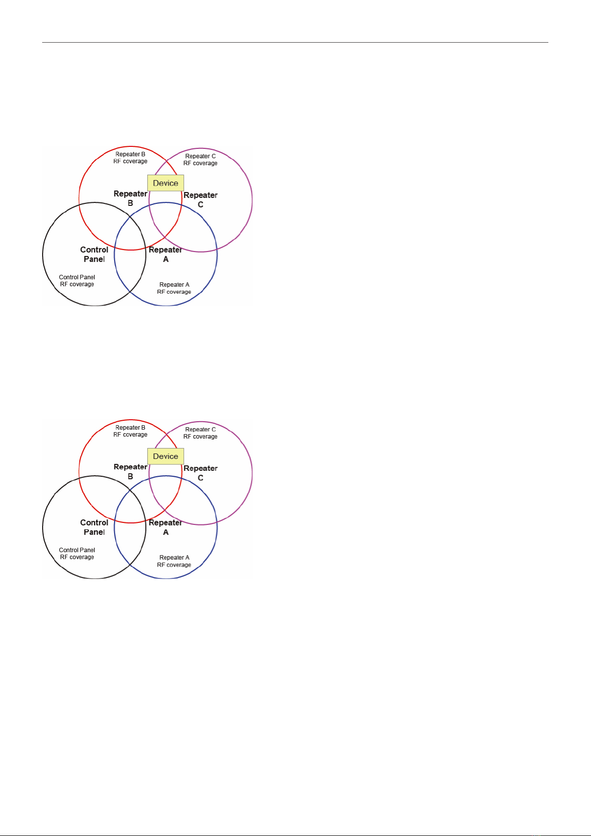
Example 1:
If the device is located between the RF coverage of multiple repeaters and the Control Panel.
From the displayed diagram, the device is located between the RF coverage areas of Repeater B and C.
Users can choose to learn the device into Repeater B only, learn into Repeater C only, or learn into both Repeaters B and C.
It is recommended to learn the device into Repeater B only (and not to Repeater C) to reduce signal traffic.
<NOTE>
For the above system, Repeater C is also learnt into Repeater A or B or both so the signals from Repeater C can be relayed to the Control Panel through Repeater A
or B, or either.
Example 2:
From the displayed diagram, the device is located between the RF coverage areas of Repeater A, B and C.
Users can choose to learn the device into Repeater A only, learn into Repeater B only, learn into Repeater C only,
or learn into Repeaters A, B and C.
It is recommended to learn the device into Repeater A only or Repeater B only (and not to Repeater C) to reduce signal traffic.
<NOTE>
For the above system, Repeater C is also learnt into Repeater A or B or both so the signals from Repeater C can be relayed to the Control Panel through Repeater A
or B, or either.

11NookBox Installation Guide Repeater
For more information visit:
www.getnookbox.com
This manual suits for next models
1
Table of contents
Popular Repeater manuals by other brands


COMBA
COMBA mPICO Series user manual

Cellvine
Cellvine BDA-iDEN80-47-4B-AA General Installation & Operation Guide

Asus
Asus RP-AC53 quick start guide

miAlert
miAlert miPos2 Installation and operation manual

GDI COMMUNICATIONS
GDI COMMUNICATIONS Extreme Copper XC-RP300 owner's manual

Yaesu
Yaesu Wires-X instruction manual