Yaesu Wires-X User manual

Wide-Coverage Internet Repeater Enhancement System
WIRES-X Portable Digital Node Function
Instruction Manual
Please read this “Instruction Manual” carefully for appropriate procedure.

1
Preparation Procedure
Portable Digital Node operation requires the FT2D Transceiver and a Personal computer (Windows 7 or later) with USB
terminal.
User registration (acquire an ID number)
Access the WIRES-X web page and register with the “Radio ID” of the transceiver to be used for the Portable Digital
Node station.
Refer to page 6 for details.
Install WIRES-X Software to the PC
Download “WIRES-X Software” from WIRES-X website (user login required) and install it to the PC for the node
station.
Refer to page 7 for details.
Install a USB device driver for the PC connection cable
Download the USB device driver from YAESU website and install it to a PC.
Refer to page 9 for details.
Update the firmware of the transceiver
Download the latest firmware of the transceiver from our website and update the firmware of the transceiver for the
Portable Digital Node station.
Refer to page 9 for details.
Connect the transceiver and the PC
Connecting the transceiver and the PC with the designated connection cables.
Refer to page 10 for details.
①User registration (acquire an ID number)
②Install WIRES-X Software to the PC
③Install the connection cable USB device driver
④Update the firmware of the transceiver
⑤Connect the transceiver and the PC
The following connecting cable is required.
• SCU-39 WIRES-X Connection Cable Kit
(The SCU-39 includes SCU-19, CT - 44, and two audio cables.)

2
Table of contents
Preparation Procedure ................................................................................................................................ 1
Introduction .................................................................................................................................................. 3
What is WIRES-X? .................................................................................................................................................... 3
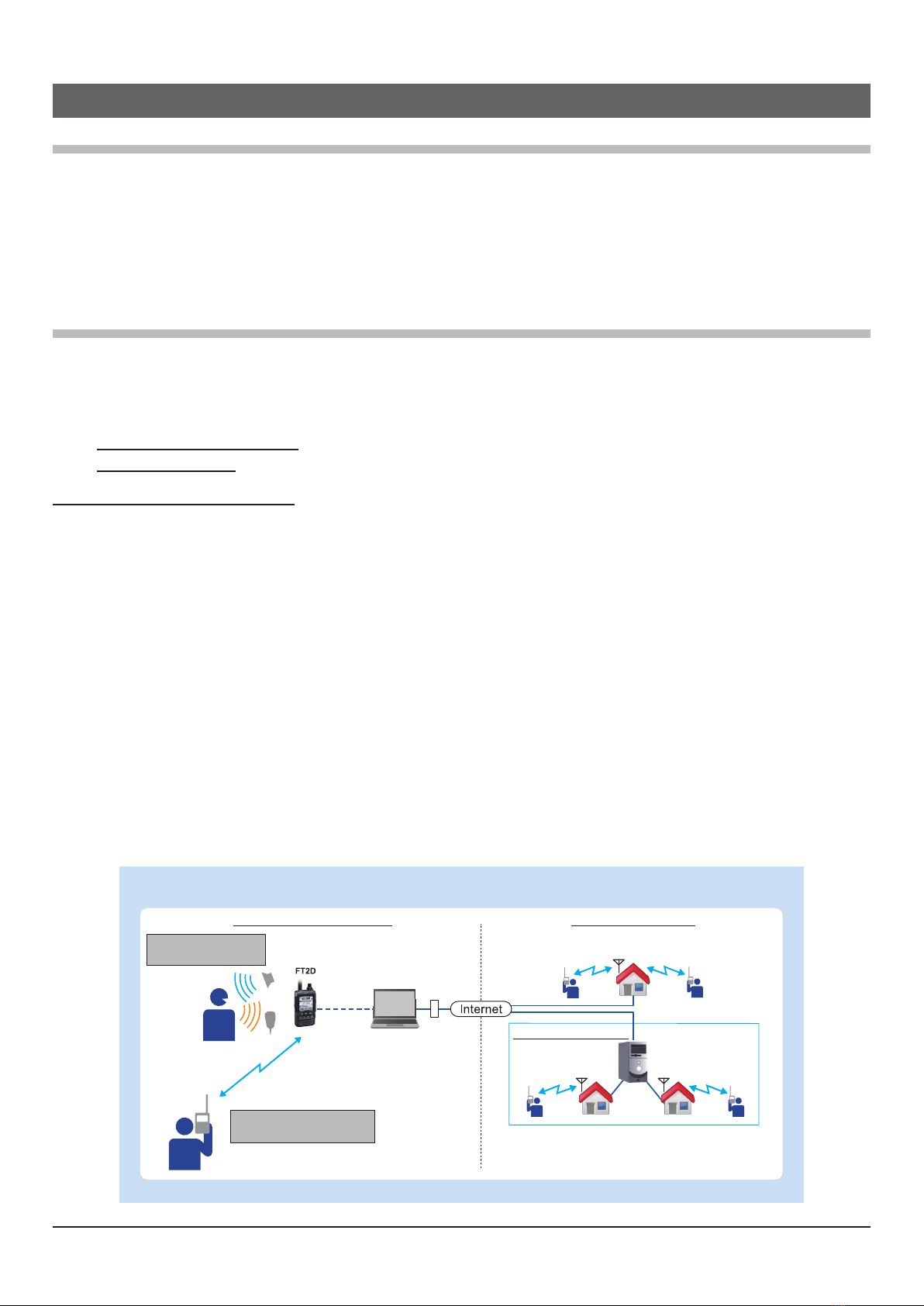
What is WIRES-X Portable Digital Node Function? .................................................................................................. 3
System Requirements (Operating Environment) ....................................................................................................... 5
Preparation ................................................................................................................................................... 6
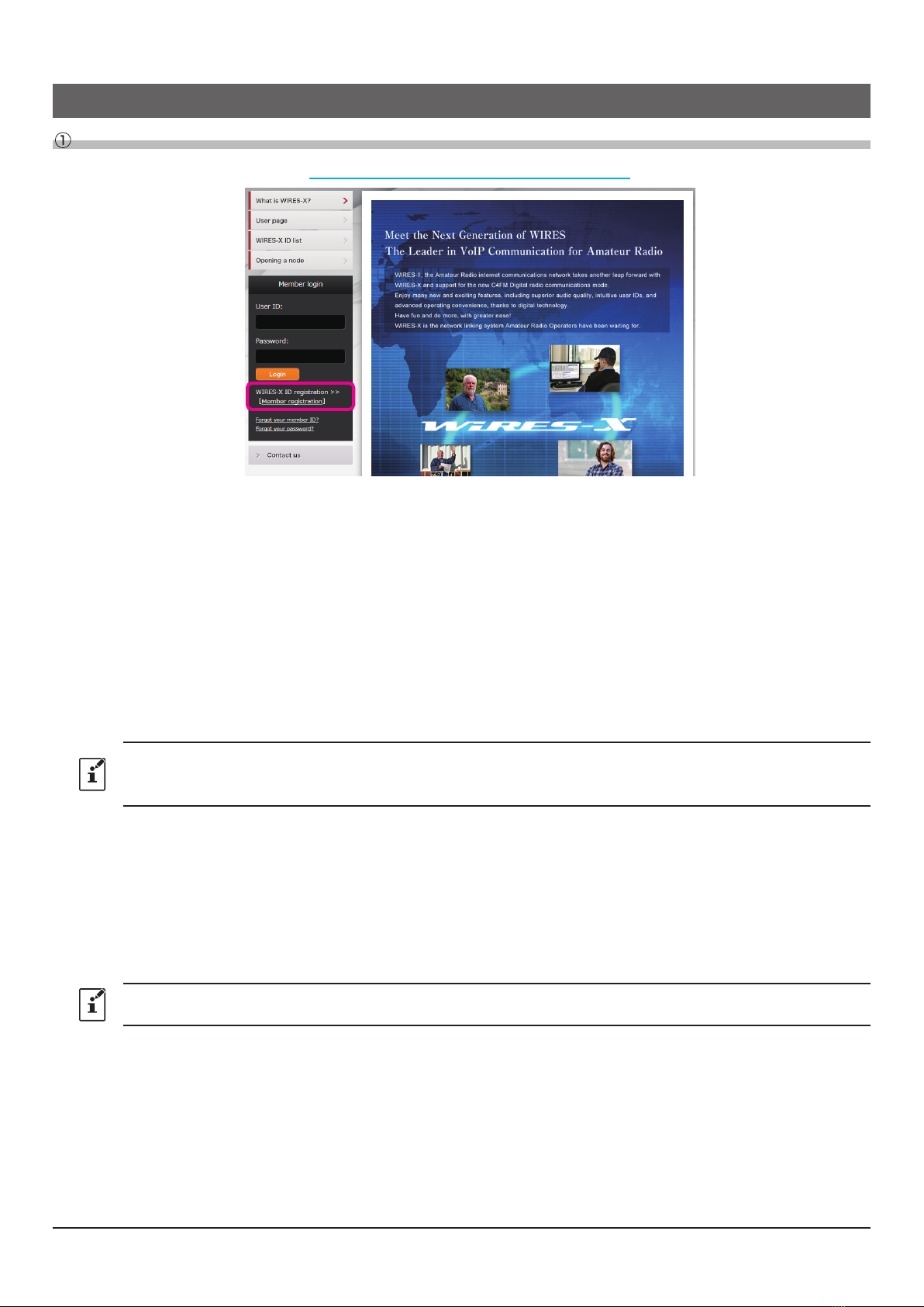
User registration (acquire an ID number) ............................................................................................................. 6
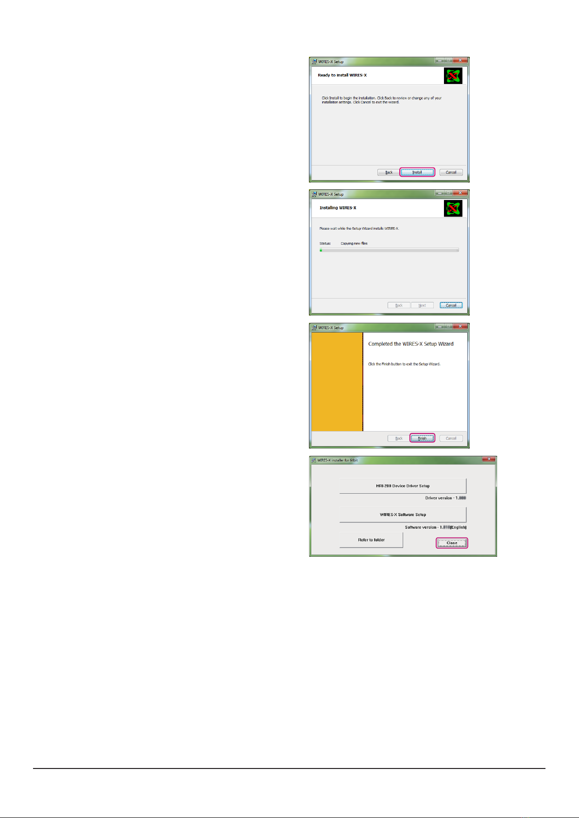
Install latest WIRES-X software to the PC ........................................................................................................... 7
Install the USB driver for the PC connection cable .............................................................................................. 9
Update the firmware of the transceiver ................................................................................................................ 9
Connect the transceiver and the PC .................................................................................................................. 10
Communicating only with C4FM digital mode (Portable Digital Node mode) ............................................ 10
Communicating with digital or analog FM mode (Portable HRI Mode) ....................................................... 10
Initial Setting (setting is required only once at the beginning) ............................................................. 12
Start the transceiver ................................................................................................................................................ 12
Starting the WIRES-X software ............................................................................................................................... 12
Communication port setting ..................................................................................................................................... 12
Authenticate (activate) the WIRES-X server ........................................................................................................... 13
Transceiver settings (Access Point only) ................................................................................................................. 14
Basic Operation ......................................................................................................................................... 16
Using the Portable Digital Node Mode .................................................................................................................... 16
Connecting the transceiver and the PC .............................................................................................................. 16
Starting the WIRES-X software .......................................................................................................................... 16
Starting the transceiver in special mode ............................................................................................................ 16
Setting the transceiver (Access Point only) ........................................................................................................ 16
Start operation of Portable Node ........................................................................................................................ 18
Connecting to a node or a room on the Internet ................................................................................................ 20
Communicating with other station ...................................................................................................................... 24
Disconnecting from the node or room ................................................................................................................ 24
Closing the WIRES-X software .......................................................................................................................... 24
Using the Portable HRI Mode .................................................................................................................................. 26
Connecting the transceiver and the PC .............................................................................................................. 26
Starting the WIRES-X software .......................................................................................................................... 26
Starting the transceiver in special mode ............................................................................................................ 26
Connecting a node or a room by operating the WIRES-X software on the PC .................................................. 26
Communicating with other station ...................................................................................................................... 27
Disconnecting from the node or room ................................................................................................................ 27
Closing the WIRES-X software .......................................................................................................................... 27
WIRES-X Software Main Screen ............................................................................................................................. 28
Functions to use as necessary ................................................................................................................ 30
Audio volume adjustment of PC (Portable HRI Mode only) .................................................................................... 30
Adjusting Audio Level in the Access Point (Portable HRI Mode) ....................................................................... 30
Adjusting Audio Level in the Direct Operation (Portable HRI Mode) .................................................................. 32
FT2D Direct Operation dedicated function .............................................................................................................. 36
Bookmarking frequently connected Nodes or Rooms ............................................................................................. 37
Bookmarking Nodes or Rooms .......................................................................................................................... 37
Operating the transceiver in Portable HRI Mode ..................................................................................................... 37
FT2D .................................................................................................................................................................. 37
About this manual
Reference icon symbols and conventions are used in this manual. Their meanings are described in the below chart.
Symbols Description
This icon indicates cautions and information that should be read.
This icon indicates notes, tips and information that should be read.

3
Introduction
What is WIRES-X?
WIRES (Wide-coverage Internet Repeater Enhancement System) is an Internet communication system which expands
the range of amateur radio communication. WIRES-X uses local nodes (stations connected to the Internet via PCs)
as access points to relay communications of conventional amateur radio stations. Mobile stations using WIRES-X can
communicate with amateur stations all over the world by using a local node access station operating within an amateur
band. WIRES-X supports the new C4FM digital communications mode, enabling C4FM digital signals to be repeated
without deterioration of the communication quality. In addition, several new functions making use of digital formats are
also made available.
What is WIRES-X Portable Digital Node Function?
Using the WIRES-X Portable Digital Node function, you can operate a WIRES-X digital node station by directly
connecting the FT2D C4FM digital transceiver with the PC. The HRI-200 Internet interface kit is not needed and no
fixed or dynamic global IP address is required).
There are two operating modes of the WIRES-X Portable Digital Node function:
Portable Digital Node Mode capable of Internet communication with digital stations.
Portable HRI mode capable of Internet communication with both digital station and analog stations.
Portable Digital Node Mode
(Supports Internet communication only in C4FM Digital Mode)
Requires a Yaesu C4FM Portable Digital Node capable transceiver (FT2D as of 12/2018 or firmware updated) an SCU-
19 USB Connection Cable (FT2D) and a PC with WIRES-X Software and Internet connection.
Two forms of WIRES-X Access are supported, “Access Point” and “Direct Operation”.
In “Access Point” the Portable Node station (FT2D) can be used to communicate “On Air and relay nearby local C4FM
digital transceivers, while simultaneously connected with the Internet WIRES-X digital rooms and digital node stations.
In “Direct Operation”, the Portable Node (FT2D) station transceiver is used only for WIRES-X internet communications
without transmitting or receiving local “On Air” radio signals.
Access Point
In this mode, WIRES-X C4FM communications are made by either directly using the USB connected FT2D Node
Station PTT, microphone, and speaker, or via another local C4FM transceiver communicating on frequency with the
USB connected FT2D Node Station. The FT2D Node Station connects directly to the PC and internet, and commu-
nicates with WIRES-X Nodes and Rooms. The FT2D Node Station relays the local C4FM stations and signals to
the internet and transmits the internet Node and Room signals to the local stations. This mode allows the flexibility
to operate the Portable Digital Node directly with a single USB connected FT2D transceiver, or to access WIRES-X
Nodes and Rooms from one or several local C4FM transceivers.
Access Point Illustration
C4FM Digital C4FM Digital
C4FM Digital
Portable Digital Node Station WIRES-X Node Station
WIRES-X Digital Room
Digital Node Station
Communicate by RF to access the
Portable Digital Node station from
other C4FM digital transceivers.
C4FM Digital
Digital Node Station Digital Node Station
C4FM Digital
Press the PTT switch on
the transceiver connected
to the PC to communicate.

4
Direct Operation
In this mode, WIRES-X C4FM communications are made directly by using the USB connected FT2D Transceiver
Node Station. The microphone signal is sent only to the PC and the Internet. The Internet signals are heard only in
the FT2D speaker. In this Direct Operation, the FT2D transceiver does not transmit or receive over the air.
Direct Operation Illustration
C4FM Digital C4FM Digital
WIRES-X Digital Room
Digital Node Station
C4FM Digital
Digital Node Station Digital Node Station
C4FM Digital
WIRES-X Node Station
Press the PTT switch on
the transceiver connected
to the PC to communicate.
Portable Digital Node Station
Portable HRI Mode
(Supports Internet communication only in both C4FM Digital Mode and Analog Mode)
Requires a Yaesu C4FM Portable Digital Node capable transceiver (FT2D as 12/2018) an SCU-19 USB (FT2D)
Connection Cable, a CT-44 adapter, two audio cables and a PC with WIRES-X Software and Internet connection.
(The HRI-200 interface is not used).
(The SCU-19 USB Connection Cable, CT-44 adapter & two audio cables are available in the SCU-39 connection kit)
In the Portable HRI configuration, either the Access Point or the Direct Operation may be activated:
Access Point
(Portable HRI Mode)
In this mode, WIRES-X C4FM and Analog communications are made via another local C4FM transceiver
communicating on frequency with the USB connected FT2D Node Station. The FT2D Node Station relays the local
C4FM and Analog signals to the internet and transmits the internet Node and Room signals to the local stations. This
Node mode allows the flexibility to operate the Portable Digital Node to access WIRES-X Nodes and Rooms from one
or several local C4FM transceivers.
Access Point (Portable HRI Mode)Illustration
Portable Digital Node Station
C4FM Digital
C4FM Digital Analog FM
WIRES-X Room
Digital Node Station
C4FM Digital
Digital Node Station Analog Node Station
Analog FM
Analog Node Station
WIRES-X Node Station
Communicate by RF to access the
Portable Digital Node station from
other C4FM digital transceivers.
Direct Operation
(Portable HRI Mode)
In this mode, you can communicate in digital mode or analog mode via the Internet. WIRES-X communications are
made directly by using the USB connected FT2D Transceiver. The microphone signal is sent only to the PC and the In-
ternet. The Internet signals are heard only in the FT2D speaker. In this Direct Operation, the FT2D transceiver does not
transmit or receive over the air.

5
Direct Operation (Portable HRI Mode) Illustration
WIRES-X Node Station
C4FM Digital Analog FM
WIRES-X Room
Digital Node Station
C4FM Digital
Digital Node Station Analog Node Station
Analog FM
Analog Node Station
Press the PTT switch on
the transceiver connected
to the PC to communicate.
Portable Digital Node Station
With the WIRES-X Portable Digital Node function, you cannot operate a a WIRES-X Room (Including a digital room) or
use the remote-control function from the outside.
System Requirements (Operating Environment)
Supported Transceiver
• FT2D
(As of Dec 2018)
Connection Cable
• SCU-39 WIRES-X Connection Cable Kit (Option)
(The SCU-39 includes SCU-19 and CT-44, and two audio cables.)
The latest WIRES-X Software and Transceiver Firmware
Update to the latest software and firmware on YAESU website.
• WIRES-X Software:
Ver.1.500 or later
• FT2D MAIN: Ver.3.10 or later, SUB: Ver.2.01 or later, DSP: Ver.4.31 or later
PC
•OS:Microsoft®Windows®7 / 8.1 / 10
• Processor Clock Frequency:2.0 GHz or faster
•HDD:1 GB or more of available space
•RAM:2 GB or more
• Display resolution:1366 x 768 16-bit high color or higher (32-bit true color is recommended)
• USB port:USB 2.0 (Full Speed)
• LAN port:100BASE-TX/1000BASE-T or Wi-Fi:IEEE 802.11 b or higher
• Audio Interfaces*1
*1Sound function is also required when using the “Portable Digital Node mode” or “Portable HRI Mode”.
Furthermore, when communicating in “Direct Operation” in “Portable HRI Mode”, the sound function of the
personal computer to be used must have the function “audio input from the microphone terminal pass to the
speaker output” function.
• 3.5Φspeakerterminal,3.5Φmicrophoneterminal.*2 (It is necessary only for Internet communication in “Portable
HRI Mode”.)
*2 Inthecaseofadedicatedterminalsuchasalaptop,convertittoa3.5Φspeakerterminaland3.5Φmicrophone
terminal with a commercially available conversion cable.
• Speaker (
It is necessary only when communicating in
“
Direct Operation
”
in “Portable HRI Mode”.)
Internet Connection
•ADSL 8 Mbps or faster (No fixed or dynamic global IP address is required.)
When the Internet line speed is low or unstable, the sound may be interrupted or the connection of the WIRES-X
connection may become unstable.

6
Preparation
User registration (acquire an ID number)
1. Access to the WIRES-X website (https://www.yaesu.com/jp/en/wires-x/index.php).
2. Click [Member Registration] on the left side of the screen.
The “Member registration” page opens.
3. On the “Member registration” page, enter the e-mail address to be used for registration and click the [Send]
button.
You will promptly receive an e-mail with an URL address to the website for registration.
4. Click the URL address of an e-mail to open the website.
5. When “WIRES-X Server End-User License Agreement” is displayed, check “I agree to the WIRES-X server
license agreement”, then click [Agree and proceed].
6. Fill in all the fields on the “Member registration” page and send it.
In the “HRI-200 Serial Number/RADIO ID” field, enter the “RADIO ID” of the transceiver used for the node station
(RADIO ID: 5-digit alphanumeric ID unique to the transceiver).
The transceiver's RADIO ID is a combination of five letters and numbers. Since the RADIO ID is distinguished
between uppercase and lowercase letters of the alphabet, please input the RADIO ID displayed on the screen exactly
as it is.
The “RADIO ID” of the transceiver may be displayed using the following procedure:
•FT2D
(1) Press and hold [DISP] key to open the setup menu.
(2) Touch [GM].
(3) Touch [2 RADIO ID CHECK].
7. When registration is completed, e-mail with the Node ID and the Room ID will be sent to your email address.
Member registration is completed.
Completion of registration usually takes 2 to 3 business days.

7
Install latest WIRES-X software to the PC
• This is not necessary if the latest WIRES-X software (Ver.1.500 or higher) is already installed on the PC to be used.
• The latest WIRES-X software must also be installed on the transceiver that is establishing the connected room or the
directly connected node station. (When WIRES-X software with Ver. 1.400 or higher is not installed, you cannot connect
to a portable node station.)
1. User login to the WIRES-X web site. Download and
unzip the “wx****en.zip” file of the latest WIRES-X
software
(Ver.1.500 or higher)
.
2. Execute the “Install.exe” file in the unzipped folder.
The “WIRES-X Installer” window will appear.
3.
Click [WIRES-X Software Setup].
The “Welcome to the WIRES-X Setup Wizard” window
will appear.
4. Click [Next].
The “License” window will appear.
5. Put a check-mark in the “I accept the terms in the
License Agreement” check box, then click [Next].
The “Destination Folder” window will appear.
6. Confirm the destination where the WIRES-X software
will install and click [Next].
The “Ready to install WIRES-X” window will appear.
If you put a check-mark in the “Enable WIRES-X
Auto Start.” check box, the WIRES-X software will
run automatically when Windows starts. Even if the
WIRES-X software is terminated for some reason, it
will reboot automatically.

8
7. Click [Install].
Software installation will start.
When installation completes, the “Completed the
WIRES-X Setup Wizard” window will appear.
8. Click [Finish].
When WIRES-X software installation has been
completed properly, the [Wires-X] icon will appear on the
Windows desktop.
9. Click [Close] in the “WIRES-X installer” windows
Installation of the WIRES-X software is complete.

9
Install the USB driver for the PC connection cable
This procedure is not necessary if the USB driver of the SCU-19* is already installed on the PC to be used.
*(The SCU-19 is included in the SCU-39 kit.)
1. Download the SCU-19 USB driver from YAESU website (http://www.yaesu.com/).
2. Unzip the downloaded file and copy all the files to the desired folder.
3. Refer to the “Driver Installation Manual” PDF file in the folder and install the USB driver on the PC.
Update the firmware of the transceiver
This procedure is not necessary if the firmware of the transceiver used for the Portable Digital Node station is the latest
version already posted on YAESU website.
1. To check the firmware version of the transceiver, use the following procedure:
FT2D
(1) Press and hold the [DISP] key to display “SETUP MENU”, then touch [DISPLAY].
(2) Rotate the DIAL knob, then touch [11 SOFTWARE VERSION].
The firmware version of “Main” and “Sub”, “DSP” will be displayed.
FTM-100DR/DE
(1) Press and hold the [DISP](SETUP) key to display “SETUP MENU”.
(2) Rotate the DIAL to select [13 RST/CLONE].
(3) Press the Press the [DISP](SETUP) key.
(4) Rotate the DIAL to select [8 SOFTWARE VERSION], then press the [DISP](SETUP) key.
The firmware version of “MAIN CPU” and “PANEL CPU”, “DSP CPU” will be displayed.
FTM-400XDR/DE, FTM-400DR/DE
(1) Press and hold the [DISP](SETUP) key to display “SETUP MENU”.
(2) Touch [RESET/CLONE].
The firmware version of “MAIN” will be displayed on the top of the screen.
(3) Touch [BACK].
(4) Touch [TX/RX].
(5) Touch [DIGITAL].
(6) Rotate the DIAL knob to select [5 DSP VERSION].
The “DSP” firmware version will be displayed to the right of [5 DSP VERSION].
For details on checking the firmware version of the transceiver other than the above, refer to the owner's manual of each
transceiver.
2. If the firmware version of the transceiver is the latest firmware as indicated on YAESU website (http://www.yaesu.
com/), update is not necessary.
Proceed to “
Connect the transceiver and the PC” (page 10).
3. Download the latest firmware from YAESU website (http://www.yaesu.com/).
4. Unzip the downloaded file and copy all the files to the desired folder.
5. Refer to the “Firmware Update Manual” PDF file in the folder and update the firmware of the transceiver.
Be sure to use “Supplied USB cable with FT2D” for FT2D firmware update. The PC connection cable SCU-19 cannot be
used for FT2D firmware update.

10
Connect the transceiver and the PC
Do not connect the connection cable to the PC before the installation of the USB device driver is completed. The wrong
device driver may be installed and it may not operate correctly.
To communicate with an analog FM station, refer to “Internet communication in digital mode or analog mode (Portable HRI
Mode)” and connect the transceiver and the PC.
Communicating only with C4FM digital mode (Portable Digital Node mode)
1. Refer to the figure and connect the PC connection cable SCU-19.
(The SCU-19 is included in the optional SCU-39 kit.)
*It is not necessary to connect the microphone / speaker terminal.
USB
DATA
SCU-19
(Included in the optional SCU-39)
• To prevent RF interference, keep the antenna of the transceiver as far away from the connecting cables and PC as possible.
• It is recommended to set the transmit output power of the transceiver as low as possible for the desired communication.
The connection is complete.
Communicating with digital or analog FM mode (Portable HRI Mode)
Since the cable connection differs between Access Point and Direct Operation, please refer to the following and make
the connections according to the mode to be used.
《When operating in Access Point》
1. For the WIRES-X Node mode connection, use the SCU-19 USB Connection Cable, the CT-44 adapter & two
audio cables that are supplied in the SCU-39 Connection Kit (sold separately) as shown in the figure.
USB
Speaker
MIC
DATA
MIC/SP
Φ3.5 plug (Gray)
Φ3.5 plug (Gray)
Φ2.5 plug (Black)
Φ3.5 plug (Black)
• To prevent RF interference, keep the antenna of the transceiver as far away from the connecting cables and PC as possible.
• It is recommended to set the transmit output power of the transceiver as low as possible for the desired communication.
The connection is complete.

11
《When operating in Direct Operation》
1. For the WIRES-X Direct mode connection, use the SCU-19 USB Connection Cable, the CT-44 adapter & one of
the audio cables that are supplied in the SCU-39 Connection Kit (sold separately) as shown in the figure.
USB
MIC
DATA
MIC/SP
Φ3.5 plug (Gray)
Φ3.5 plug (Gray)
The connection is complete.

12
Initial Setting (setting is required only once at the beginning)
Start the transceiver
◎Portable Digital Node mode (Supports linking to the Internet only in C4FM digital mode)
1. Press and hold the [X] key, [BAND] key and the POWER switch to turn the transceiver ON.
“PDN” is displayed on the LCD screen.
◎Portable HRI Mode (Supports Internet communication in digital mode and analog mode)
1. Press and hold the [X] key, [BACK] key and the POWER switch to turn the transceiver ON.
“WIRES-X NODE” is displayed on the LCD screen.
Repeating the above operation will return the transceiver to the normal mode.
Starting the WIRES-X software
1. Double-click the [Wires-X] icon on the PC desktop.
・Setting the Internet access security (Only when Windows Security Alert screen appears)
If the Windows Security Alert window appears when starting
WIRES-X software, click [Allow access] to allow Internet
access from the WIRES-X software.
Communication port setting
When starting the WIRES-X software for the first time, the “COM port setting” window will appear. Set the
communication port with the transceiver connected to the PC.
1. Click [▼]in the “Serial Port Selection” column and click the COM port (displayed as “Prolific USB-to-Serial
Comm Port (COMX)”) connected to the transceiver.
• You can also select a communication port by clicking “Serial port number specify
”
and entering the COM port number
directly.
• Click the [Device Manager] to open the Windows Device Manager.
2. Click the [OK].
The communication port may be changed from the [File (F)]
menu - [Communication port] of WIRES-X software.

13
Authenticate (activate) the WIRES-X server
If the WIRES-X server authentication (activation) has not been completed on the personal computer to be used, the
“WIRES ID Activation” screen opens automatically.
1. Enter the Node ID and Room ID (both are 5-digit numbers).
The Node ID and the Room ID are described in the e-mail received when the user registration is completed.
“RADIO ID“ of the transceiver connected to the PC is automatically displayed in the serial number column. If “RADIO
ID“ is not displayed, check the connection between the transceiver and the computer again.
2. Click the [ID Entry].
When activation is completed, information on registration is automatically displayed for “User ID”, “Call Sign”, “City”,
“State”, and “Country”.
3. Click the [OK].
The information of the User ID is saved on the computer and “Settings” window will appear.
On this screen the settings such as “Comment” of your station may be added to display in the ID list.
4. Click the [OK].
The “Settings” window closes and the “Main Screen” will appear.
When using it in “Direct Operation”, “Transceiver settings (Access Point only)” (page 14) is not necessary, so the
initial setting is completed.
Proceed to
“Basic Operation” (page 16).

14
Transceiver settings (Access Point only)
When using “Access Point” of Portable HRI Mode, set the operating frequency and parameters etc. of the transceiver
by using the following procedure:
It is not necessary to make these settings when using “Direct Operation”.
When using “Access Point” of Portable Digital Node Mode, only the “Hide frequency settings” item can be set using the
following procedure. When the transceiver is connected and operation of the “Node Mode” is started, the other items settings
are transferred from the transceiver and can only be confirmed.
1.From the “File” menu, click “Transceiver”.
The “Transceiver” window will appear.
2. Set the operating frequency of the Portable Digital Node Station.
Frequency
:
Enter the operating frequency.
Narrow
Deviation
:
Select if using Narrow deviation operation.
(default: Unchecked)
DG-ID
:
Select the DG-ID (Digital Group ID) number 00 to 99 (default setting: 00)
When the DG-ID number is set to “00”, the node becomes an open node. The subcode on the right
can be set from “00” to “26”.
When DG-ID number is set to “00” and subcode is set to “00”, relay C4FM digital signals of all DG-
ID numbers.
When DG-ID number is set to “00” and subcode is set from “01” to “26”, C4FM digital signals without
the matching subcode will not be relayed. The C4FM digital transceiver accessing the WIRES-X
DG-ID “AUTO” node station is automatically set to the same subcode and can communicate while
accessing it.
• By setting the DG-ID number to “00”, the station becomes an open node station, and can be
connected from all transceivers with the WIRES-X DG-ID setting “AUTO”. When using a node
station in a restricted group, set the DG-ID to a number “01” to “99”, and then set all the group
transceivers to the same DG-ID number.
• The DG-ID Subcode cannot be used or set in Portable Digital Node mode.

15
Power
:
Set the transmission power of the transceiver.
Offset
:
For split operation, input the offset value of the frequency to be used for reception (uplink) in MHz
for the “operating frequency” that the node station uses for transmission (downlink). Leave blank if
you do not want split operation.
(default: blank)
Reverse
:
When unchecked, reception (uplink) at the operating frequency and transmission (downlink) at the
offset frequency are made.
Hide frequency
settings:
When checked, the operation information (frequency and squelch setting) will not be displayed in
the node list. It takes about 10 minutes for the setting to be reflected in the node list.
(default: Unchecked)
This is the only item that may be set when using “Access Point” in the Portable Digital Node Mode.
3. Click the [OK].
The “Transceiver” window closes and the “Main Screen” will appear.
When a microphone is connected or built in the PC, there may be cases where the sound around the PC is relayed, be sure to
remove the microphone or mute the microphone with the setting of the audio device of the PC.
When communicating via the Internet in “Portable HRI Mode”, refer to “Adjusting Audio Level in the Access Point
(Portable HRI Mode)” (page 30) or “Adjusting Audio Level in the Direct Operation (Portable HRI Mode)” (page 32)
and adjust the audio level of the computer.
The Initial setting is complete.

16
Basic Operation
Refer to “Using the Portable Digital Node Mode” or “Using the Portable HRI Mode” (page 26) according to the
mode to be used.
Using the Portable Digital Node Mode
Connecting the transceiver and the PC
Refer to “Communicating only with C4FM digital mode (Portable Digital Node mode)” (page 10) and connect
the transceiver to the PC.
Starting the WIRES-X software
1. Double click the [Wires-X] icon on the desktop of the computer screen.
The main screen of WIRES-X software is displayed.
For details on the main screen, refer to “WIRES-X Software Main Screen” (page 28).
Starting the transceiver in special mode
1. Press and hold the [X] key and the [BAND] key simultaneously, while turning the radio ON.
“PDN” is displayed at the lower right of the LCD.
2. Press the [A/B] key to select “Access Point” or “Direct Operation”.
Depending on the set operation mode, it is displayed on the frequency display as follows.
Access Point: “
(Frequency display)
”
Direct Operation: “DIRECT”
To return the transceiver to the normal mode, repeat procedure 1 above.
The portable station transceiver cannot use the News Station feature or the GM feature.
Setting the transceiver (Access Point only)
When using the “Access Point", it is necessary to set the node station transceiver parameters, such as operating fre-
quency and DG-ID number on the portable node station transceiver.
When using the “Direct Operation”, it is not necessary to set the frequency and parameters on the transceiver, just
proceed to “Start operation of Portable Node” (page 18).
1. To set the operating frequency:
Use the transceiver DIAL knob, the Numeric keypad input screen, or the memory channel to set the operating
frequency.
In the “Transceiver Setting Screen”, the portable Access Point function is not working. May be communicate
normally with C4FM digital mode (DN mode only) with the transceiver.
On the frequency setting screen, you can set and operate the following with the transceivers key and DIAL knob
settings.
Function Key or Dial
Switches between the Access Point and the Direct
Operation A/B key
Starts operation for the Portable Digital Node X key
Sets the operation frequency DIAL knob or Numeric keypad input screen
Switches between the VFO mode and the Memory
Channel mode V/M key
Moves operation to the next-highest frequency band BAND key
Sets the transmit and receive DG-ID number GM key (Press and hold)

17
Function Key or Dial
TX/BUSY LED turn OFF/ON V/M key (Press and hold)
Squelch OFF MONI key (While MONI key is pressed)
Adjusts the squelch level SQL key and DIAL knob
Enters the Set mode* DISP key (Press and hold)
Enters the BACKTRACK screen DISP key
Registering to Memory Channel [F MW] (Touch and hold)
Displays the Function Menu Screen [F MW]
Selects the Transmission Power Level [TX PWR] in the Function Menu Screen
Recalls the “HOME” channel [HOME] in the Function Menu Screen
Reverses the transmit and receive frequencies [REV] in the Function Menu Screen
Switches Busy detection between “Noise squelch” and
“DG-ID number match”.
A/B key (Press and hold)
* Some setting items in the set mode are automatically set for the Portable Digital Node function, so these
settings cannot be changed.
2. Setting the transmit and receive DG-ID number.
This procedure is unnecessary if the transceiver is already set to the required transmit and receive DG-ID
number.
Since the transmit and receive DG-ID number is “TX: 00” and “RX: 00”, it operates as an open node and is
accessible from all transceivers using C4FM digital mode.
When using a portable node station to be accessed only by the specific members, set the transmit and receive
DG-ID to a number other than “00”.
• In the Access Point, if the receive DG-ID is set to other “00”, set the
transmit
DG-ID number to the same DG-ID
number. Note that setting to a different number will not work properly.
• When setting the receive DG-ID number to “00” and then setting the transmission DG-ID number to anything other
than “00”, the audio of all received C4FM digital stations will be heard on the speaker, but for the transmission DG-
ID Only the matched communication is relayed to the opposite station on the Internet.
• The DG-ID Subcode cannot be used or set in Portable Digital Node mode.
1. Press and hold the [GM] key.
The DG-ID SETUP screen is displayed on the LCD.
2. Press the [GM] key, then rotate the DIAL knob to set the transmit DG-ID
number (DG-ID TX).
While setting the DG-ID number, press and hold the [DISP] key will set the
transmit and the receive DG-ID numbers to “00”.

18
3. Press the [GM] key, then rotate the DIAL knob to select “DG-ID RX”.
4. Press the [GM] key, then rotate the DIAL knob to set the receive DG-ID (DG-ID
RX).
5. Press and hold the [DISP] key, to save the setting and return to normal
operation.
The setting of the transceiver is complete.
Start operation of Portable Node
1. Press the [X] key on the portable node's transceiver.
The “
X
” icon flashes on the upper left of the LCD screen.
• The display screen example uses the “Access Point” screen. In “Direct Operation”,
“DIRECT” is displayed instead of frequency
• If the “
X
” icon does not blink when the [X] key is pressed, communication between the
transceiver connected to the PC and the WIRES-X software has not been established,
so check the cable connection and USB driver installation.
• To cancel the connection, press and hold the [X] key.
2. When the operation of the portable node is started, the “
X
” icon changes from
blinking to lit and the Node ID and the city of its own station are displayed.
Depending on the history of the previously connected node on the internet and the
current connection status of the portable node, one of the following four screen is
displayed.
If the portable node is not connected to a node or a room on the Internet
①When connection history is not stored
The lower connection destination display will be blank.
②When connection history is stored
The ID of the previous connected the Node or Room will blink.
Press the PTT switch or touch [blinking connection ID] to connect.

19
If the portable node is already connected to a node or a room on the Internet
③
When connected to the same node or room as the ID of the previous connection history
The current connection ID is displayed in the lower part of the LCD. To
communicate with this connection, proceed to “Communicating with the
other station” (page 24).
④
When connected to a node or room different from the previous connection history
The “►”andthecurrent connection ID is displayed in the lower part of the
LCD.
When the DIAL knob is turned, the previous connection destination ID will
blink. In this case, press the PTT switch or touch [blinking connection ID] to
connect to the previous connection ID.
While operating the Portable Node, may be not possible to switch between “Access Point” and “Direct Operation”. Press
and hold the [X] key to return to the transceiver setting screen, then press the [A/B] key.
While operating the portable node, may be set and operate the following on the portable node transceiver.
Function Key or Dial
Return to the transceiver setting screen X key (Press and hold)
Squelch OFF MONI key (While MONI key is pressed)
Adjusts the squelch level SQL key and DIAL knob
Enters the BACKTRACK screen DISP key
Enters the Set mode* DISP key (Press and hold)
Displays the frequency display screen V/M key
Displays the Function Menu Screen [F MW]
Selects the Transmission Power Level [TX PWR] in the Function Menu Screen
Selects Speaker Mute A/B key
Disconnects a node or a room on the Internet BAND key (Press and hold)
* Some setting items in the set mode are automatically set for the Portable Digital Node function, so the settings
cannot be changed.
Setting the speaker mute
You can mute the audio output of the speaker of the node station transceiver.
You cannot set it in Direct Operation.
Press [A/B] key each time toggles the mute mode as follows.
MUTE OFF MUTE ALLMUTE TX MUTE RX MUTE OFF
・・・
MUTE OFF: Disable mute.
MUTE ALL: Mute both the received voice from the C4FM digital station and the voice from the node station on the
Internet.
MUTE RX: Mute the received voice from the C4FM digital station.
MUTE TX: Mute the voice from the node station on the Internet.
When the MUTE setting is enabled, the mute icon “ ” blinks at the top of the LCD.
In the Digital Portable Access Point, you can connect only to a Digital Room or a Digital Node. When connecting to an
analog node station, please use Portable HRI Mode.
When the frequency setting screen is displayed, the mute setting status is displayed for about 1 second on the screen
each time you press the [A/B] key.
Table of contents
Other Yaesu Repeater manuals

Yaesu
Yaesu DR-1 User manual

Yaesu
Yaesu WIRES-X FT3D User manual

Yaesu
Yaesu DR-1X User manual

Yaesu
Yaesu FTR-710A User manual

Yaesu
Yaesu WIRES-X HRI-200 User manual

Yaesu
Yaesu DR-1X User manual

Yaesu
Yaesu DR-2X Manual

Yaesu
Yaesu DR-1X User manual

Yaesu
Yaesu DR-1X User manual

Yaesu
Yaesu WIRES-X TM-400FT5D Installation and operation manual
Popular Repeater manuals by other brands

Motorola solutions
Motorola solutions Futurecom PDR8000 Programming guide

DMP Electronics
DMP Electronics 1100RINT installation guide

Nikrans
Nikrans NS200-GSM+4G installation guide

Nikrans
Nikrans NS-500GW installation guide

DOSCH&AMAND Products
DOSCH&AMAND Products DA1270 manual

DALCNET
DALCNET CASAMBI CBU-REPEATER-USB Device manual