3
FSM3 Series
How to order
C Flow direction
D Body material/compatible uids
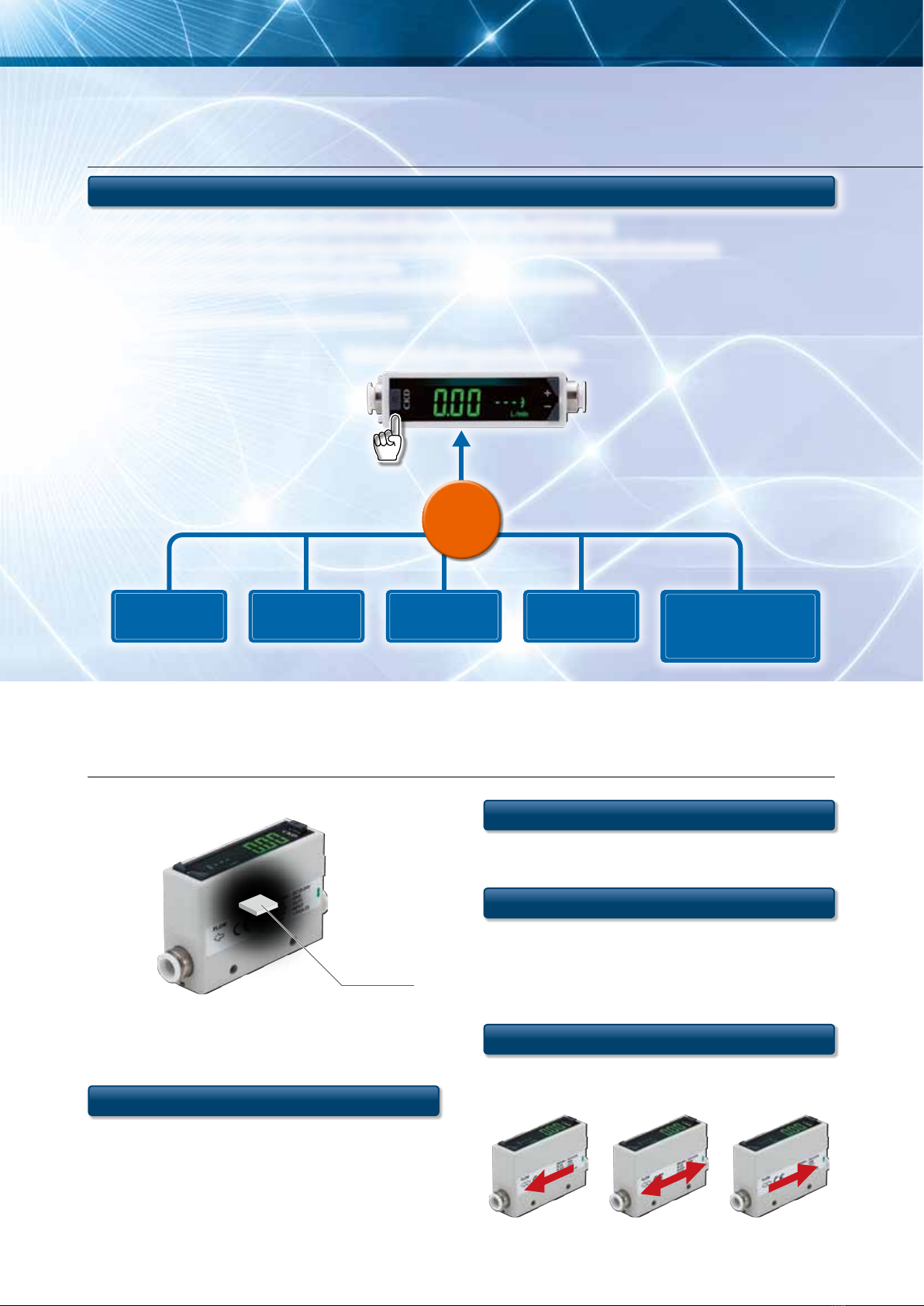
A Display
Model No.
E Port size
H Unit specications
L Attachments
F Piping direction
G Output specications
J Cable
M Clean-room
specications
FSM3
BH
P80
UL 1 1 A N1 B M R Code Content
ADisplay
LLiquid crystal display
BFlow rate range (full scale ow rate)
005 500 mL/min 500 50 L/min
010 1 L/min 101 100 L/min
020 2 L/min 201 200 L/min
050 5 L/min 501 500 L/min
100 10 L/min 102 1000 L/min
200 20 L/min
CFlow direction
UUni-direction
BBi-direction
DBody material/compatible uids
Body material Compatible uids
1Resin
Air (Gas can be changed)
EPort size
BH Push-in (for φ4 mm tube) AB G1/8 *2
CH Push-in (for φ6 mm tube) BB G1/4 *2
DH Push-in (for φ8 mm tube) CB G1/2 *2
EH Push-in (for φ10 mm tube) AC NPT1/8
HH Push-in (for φ1/4" tube) BC NPT1/4
JH Push-in (for φ3/8" tube) CC NPT1/2
AA Rc1/8
BA Rc1/4
CA Rc1/2
FPiping direction
1Straight
2Elbow *3
GOutput specications
Analog output Switch output Copy function
A1-point
(Voltage
output)
1-5 V
1-point (NPN) With
B2-point (NPN) -
C1-point (PNP) With
D2-point (PNP) -
E1-point
(Current
output)
4-20 mA
1-point (NPN) With
F2-point (NPN) -
G1-point (PNP) With
H2-point (PNP) -
HUnit specications
1SI units only
2
With unit change function (only for overseas) *4
IValve option
NNone
T
With needle valve (only for models 200 L or less)
E
EXA connecting tting (EXA sold separately) *5, *6
JCable
Blank None
A5 conductor 1 m
B5 conductor 3 m
KMounting attachments *7, *8
Blank None
HBracket 1 (for models 200 L or less)
JBracket 2 (for models 500 or 1000 L)
K
Panel mounting (for sensor products of models 200 L or less)
L
Panel mounting (for needle valves of models 200 L or less)
MDIN rail mounting (for models 200 L or less)
LAttachments
Blank None
RCompany certication
SCompany certication + traceability certicate
MClean-room specications
Blank None
P70 Anti-dust generation *9
P80 Oil prohibited *10
Precautions for model No. selection
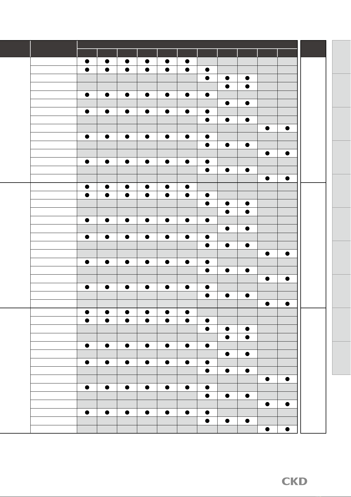
*1: During selection, always check the compatibility table on the
next page.
*2: Note that if you mount the elbow fitting in a downward position,
it will interfere with the DIN rail mounting.
*3: Check using the connection shape and dimensions (page 5) of
the G screw when selecting.
*4: The model with unit change cannot be sold in Japan.
*5: Connection to solenoid valves (EXA Series) is possible with the
dedicated fitting. Refer to page 41.
*6: Be sure to set EXA to the OUT side of the product. Use a lead
wire for the EXA coil option. The DIN terminal box cannot be
mounted because it will cause interference. After making sure it
is connected firmly, confirm that there is no external leakage.
*7: Note that the bracket mounting position may interfere with the
elbow fitting.
*8: Optional parts will come with the product. They are not pre-
assembled.
*9: Product surface is degreased before packaging and heat sealed
into an antistatic bag on the clean bench (Class 1000 and over).
*10: The wetted section is degreased in addition to the
specifications on P70.
I Valve
option
K Mounting
attachments
[Example of model No.]
FSM3-L005U1BH1A1N-BMR-P80
Model: RAPIFLOW FSM3 Series
ADisplay L :
Liquid crystal display
BFlow rate range
005
:500 mL/min
CFlow direction U:Uni-direction
D
Body material/compatible fluids
1:Resin/air
EPort size BH :Push-in
(φ4 mm for tube)
FPiping direction 1:Straight
GOutput
specifications
A :
Analog voltage output ×1,
NPN Switch output ×1,
with copy function
HUnit specifications 1:SI units only
IValve option N:None
JCable B:5 conductor 3m
K
Mounting attachments
M:DIN rail mount
LAttachments R : Company certification
M
Clean-room specifications
P80
:Oil prohibited
B Flow rate range
(full scale ow rate)
005
LCD displayBar display
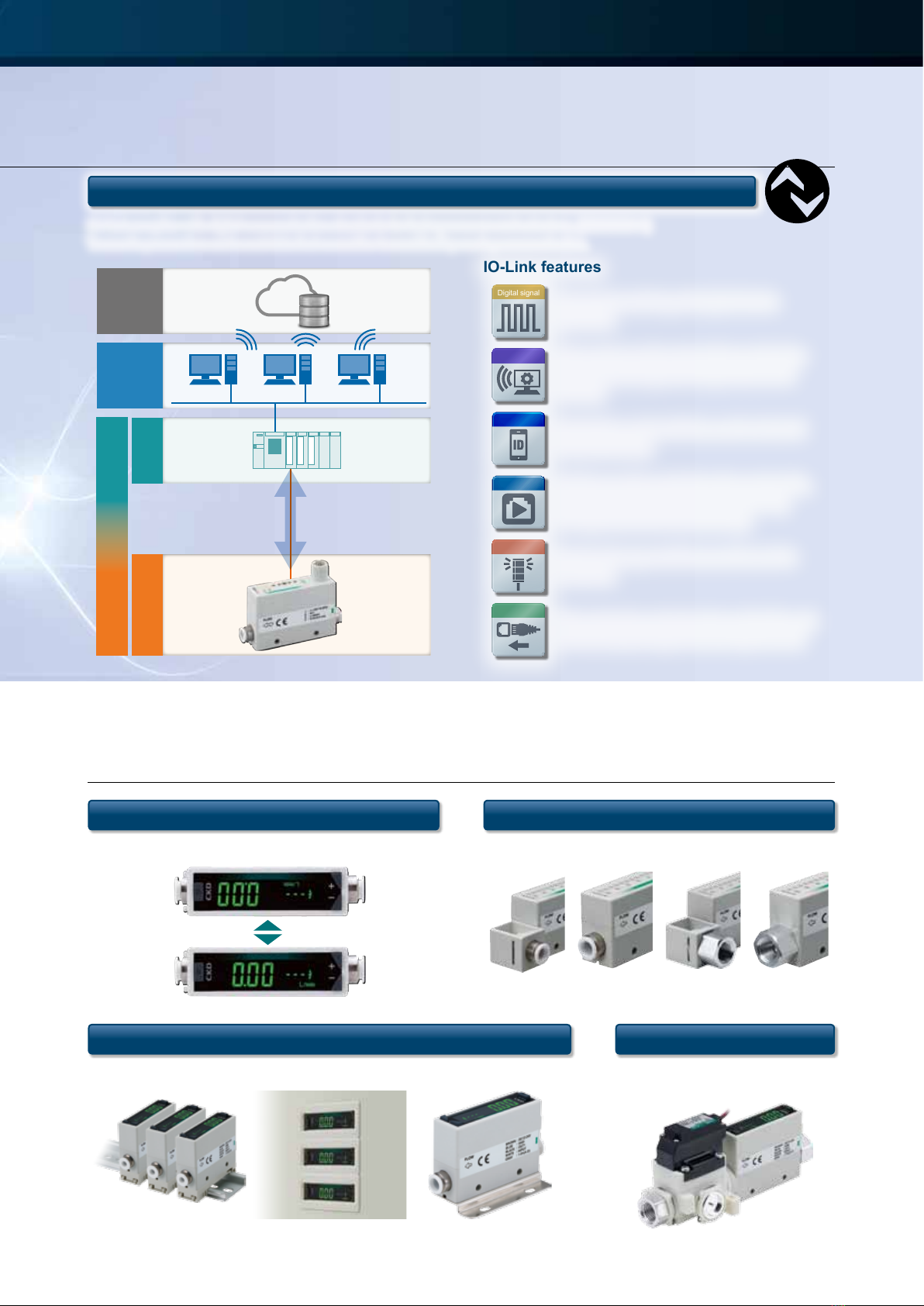
IO
-
Link
Internal
structure
Separate
display
Technical
data
Operating
method
Optional
products
Safety
precautions
Related
products