INDRA Pioneer User manual

1
Indra Pioneer
Pioneer Installation Guide

Contents
General Description
Overview and Intended use environment
Protective Earth, Simultaneous Touch (PESTs) Protection
General Installation Notes
Installation Procedure
Commissioning the Charger- Smart Charging Control
Load Curtailment and Calibration
Technical Specifications and Ratings
Certification:
Safety Markings and Labels
Troubleshooting
Servicing and Maintenance
Support and Contact Information
Models:
190105A101 Type 1 Tethered
190105A102 Type 2 Tethered
190105A103 Type 2 Socketed
2
3
3
4
10
11
29
31
45
46
47
48
49
50

3
General Description
This manual describes the method of installation and hardware operation of the
‘Pioneer’, where the Pioneer is a permanently installed electric
vehicle charging solution for resistive domestic and commercial loads of at least 6A
and up to 32A at 230V, 50Hz.
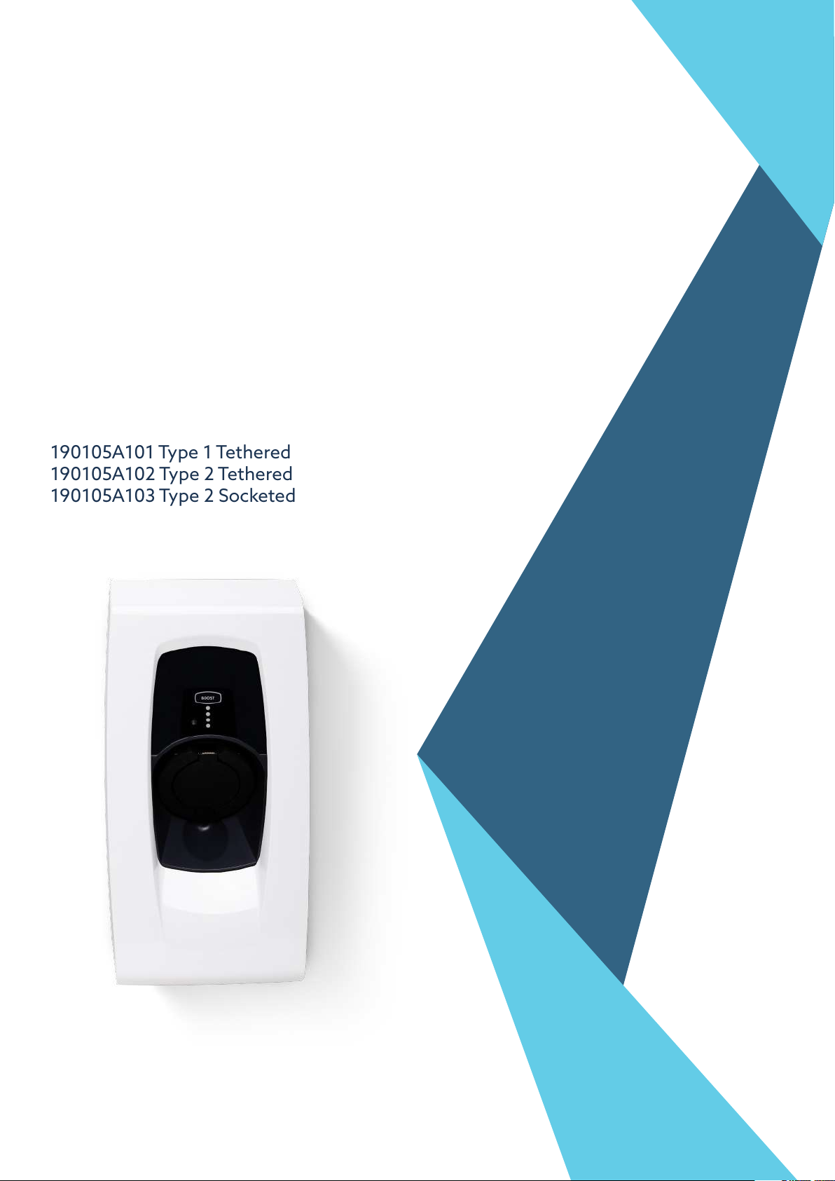
Pioneer has 3 build variants:
• Pioneer Type 1 (190105A101) has a SAE J1772 (Type 1) tethered charging
connector to be used with Type 1 socket fitted EVs
• Pioneer Type 2 (190105A102) has an IEC 62196 (Type 2) tethered charging
connector to be used with Type 2 socket fitted EVs
• Pioneer Type 2 Socket (190105A103) can be used with multiple types of
charging cables, provided at least one end of the cable is fitted with an IEC 62196
male connector
The Pioneer works like conventional chargers, but also offers a range of
smart charging modes, designed to take advantage of local generation (e.g. solar PV),
variable rate tariffs (e.g. Time of Use), as well as schedule charging according to the live
carbon intensity of grid power. In all modes, the Pioneer calculates the best charging
schedule that gets your EV ready when you need it.
Overview and Intended use environment
The Pioneer can be classified as a ‘smart’ electric vehicle charging solution
because of its communications infrastructure which allows charging to be remotely
optimised by the ev.energy smart platform; where charging can take place when
electricity is cheapest; or if immediate charging is required, its ‘Boost’ functionality
overrides any smart grid criteria and provides instantaneous charging capability.
Charging using the Pioneer can take place at up to 7kW, but due to modulation
capability (measured by the external CT clamp) this power output level can also be
reduced.
The Pioneer is intended for both indoor and outdoor installation, securely mounted to
any retaining wall.
In its operating environment, the temperature must be between -20 and 50°C, with
humidity between 10% to 85% non-condensing. Supply voltage should be 230V AC
at 50Hz, rated up to 32Amps, to allow for maximum charging capability.

4
Protective Earth, Simultaneous Touch (PESTs) Protection
The Pioneer’s PEST solution can operate under four of the indents of BS
7671:2018+A2:2022 Amendment 1; section 722.411.4.1, for the purposes of design
/installation we have two modes of operation which Indra call A & B. Mode A can be
configured with or without a reference electrode.
The safest installation configuration is always mode A with reference electrode.
• Mode A with reference electrode – Indent iii – PME (Protective Multiple Earthing)
as CPC with a TT reference electrode and the only method for imbalanced 3 phase
installations (3 phase installations that do not meet the requirements of indent i)
• Mode A without reference electrode – For installations that do not fall under the
requirements of 722.411.4, TT installations, indoor installations, balanced 3 phase
installations (indent i), installations where PME is bonded to Earth in accordance
with indent ii and installations where protection is provided by a third party device
(e.g. matt:e).

• Mode B - PME as CPC with trip on L-N voltage measurement. No reference
electrode. For installations where an Earth Rod is not possible and/or there are
no simultaneous contact or touch voltage risks present. Consideration should \
be given to nuisance trips where the line to neutral voltage may regularly exceed
253v, especially where local renewables are present, Mode A is less sensitive to
nuisance tripping.
5

6
BS7671. 18th Ed Am1
PEN Fault
Ref Earth Electrode
Phase Imbalance
(1) L – N Trip
(2) L – TT Ref Trip
(3) PME – TT Ref Trip
Dedicated CPC
Earth Electrode
Relay Weld detection
DC 6mA Protection
Protection for installs
with three independent
earthing systems (rare)
Indra’s unique PEST safety features
3 phase
property capable
Touch Voltage
Simultaneous Contact
722.411.4.1 (iii)
Full protection
Full protection
230 +/- 12% RMS
230 +/- 12% RMS
30v RMS
Required – COPv4
Not required
Full protection
Full protection
Manual management
of risk
Yes
Full protection
Full protection
Limited protection
Not required
Limited protection
230 +/- 12% RMS
Faults not detected
Faults not detected
Not required
Full protection
Full protection
Manual management
of risk
Yes
Manual management
of risk
Manual management
of risk
722.411.4.1 (iv)
Limited protection
Install Method /
Operation Mode
Mode A with
Electrode
Mode A without
Electrode
Mode B
PESTs Mode A essentially works by comparing three voltage readings:
1. L - N
2. L - TT Ref
3. CPC (PME) – TT Ref
722.411.4.1 (i)
722.411.4.1 (ii)
any install not under
section 722.411.4
Not required
Limited protection
230 +/- 10% RMS
Faults not detected
Faults not detected
Not required
Full protection
Full protection
Manual management
of risk
No
Manual management
of risk
Manual management
of risk

7

8
The below scenarios show these two mode cases in the event of a fault arising on
the combined Protective Earth and neutral (PEN) conductor, leading to a potentially
dangerous voltage arising on the installation earth conductor, and any conductive
surfaces connected to the (protective) earth. In this case, the user touching the EV
(and outside tap or lamp post etc) completes the circuit back to source earth.
Indra PESTS mode A
Indra PESTS mode B

9
The main earthing terminal of the installation
is connected to an installation earth electrode by
a protective conductor complying with Regulation
544.1.1. The resistance of the earth electrode to Earth
shall be such that the maximum voltage between the
main earthing terminal of the installation and Earth in
the events of an open-circuit fault in the PEN conductor
of the low voltage network supplying the installation
does not exceed 70 V rms
Protection against electric shock in a single-phase installation
is provided by a device which electrically disconnects the
vehicle from the live conductors of the supply and from
protective earth in accordance with Regulation 543.3.3.101 (ii)
within 5 s in the event of the utilisation voltage at the charge
point, between the line and neutral conductors, being greater
than 253 V rms or less that 207 V rms. The device shall
provide isolation and be selected in accordance with Table
537.4 Equivalent means of functionality could be included
within the charging equipment. Closing or resetting of the
device shall be possible only if the voltage between line and
neutral conductors is in the range 207 to 253 V rms.
Protection against electric shock is provided b a device which
electrically disconnects the vehicle from the live conductors
of the supply and from protective earth in accordance with
Regulations 543.3.3.101(ii) within 5 s in the event of the
voltage between the circuit protective conductor and earth
exceeding 70 V rms due to an open-circuit fault in the PEN
conductor of the low voltage network. The device shall provide
isolation and be selected in accordance with Table 537.4.
Closing or resetting of the device shall be possible only if the
voltage between the circuit protective conductor and Earth
does not exceed 70 V rms. Equivalent means of functionality
could be included within the charging equipment.

General Installation Notes
Pre-Installation Checks and Warnings
WARNING: FAILURE TO COMPLY WITH THESE INSTRUCTIONS
COULD PRESENT A HAZARD
A) Read these instructions fully before installing or using the Pioneer and
keep these instructions for future reference.
B) The Pioneer is designed for permanent installation and is suitable for
operation on an AC electricity supply having the same voltage and current rating
as shown on the product label.
C) The Pioneer should be installed in accordance with extant wiring regulations;
providing protection with either an upstream Type A RCD or RCBO with 40A
overcurrent protection.
D) The Pioneer MUST not be fitted alongside an upstream protection device
which claims to meet ident (iv) of BS 7671:2018+A1:2020+A2:2022 Amendment
1; section 722.411.4.1. Voltage upstream PEN Fault protection and curtailment
devices such as solutions from Matt:e and Garo have been proven to regularly
nuisance trip and may damage any Pioneer device through frequent removal
of the grid supply under load.
E) A qualified professional electrician must be used for all installation and servicing
of the Pioneer. Any servicing or tampering by a non-qualified professional
electrician will void the warranty.
F) The supply to the Pioneer MUST be isolated before installation.
G) The Pioneer MUST be connected to CPC reference.
H) The installation location MUST be structurally sound and MUST NOT be subject
to excessive dust, vibration, lint or other material build-up which could affect the
Pioneer’s proper operation.
WARNING: Protection against electric shock shall not be automatically reset.
10

Installation Procedure
Installation Kit and Tools
The Pioneer is supplied with the general screws and wall fixings that are
required to permanently fix it in position. However, it remains the responsibility
of the installer to evaluate the suitability of the installation surface and use the
appropriate fixings when appropriate.
Tools, materials and equipment
• Drill for permanent wall mounting
(as applicable for wall construction)
• Wire strippers
• Smartphone, tablet or laptop to
operate the “Installer App”
• Hand-held Multimeter/ Clamp meter
• UK EV Charging Station Test Adaptor Kit (including a three-pin plug socket)
• Wall fixings (as applicable for wall
construction)
• Type A RCD or RCBO
(40A Overcurrent Protection)
• Tri-Rated 3 Core (2P+E)
Electrical cables
• 4mm2 or 6mm2 Solar Cable (EN5061), with double insulation
• Copper plated 3/8ths 4ft electrode with lug clamping terminals
(where applicable)
• CAT5E Cable
• Torque driver (1N/m minimum
setting & calibrated)
• Torx T20 Screwdriver bit
• RJ45 male connectors
• RJ45 Crimping tool
• 6 mm Bootlace Ferrule Crimps
• 6 mm Ferrule Crimping tool
• Cable (LAN Network) tester
• Armeg Holesaw for adding mains
cable gland
• IP Rated Mains cable gland
• Krone/ IDC Punch-down tool
Hacksaw (optional)
WARNING: Protection against electric shock shall not be automatically reset.
11

12
Procedure
Existing cables MUST be inspected for damage and ensure they are suitably rated for
the Pioneer.
Choosing a location
• Select an installation location that ensures future servicing of the Pioneer,
where the back plate can be mounted flush to the wall and screws can be used
to permanently secure the charger in position.
• Make sure that all ventilation channels on the Pioneer are
free from obstruction and that the install location will not allow any
flammable material to come within 100 mm of the charger.
• The socket/ cable holster of the charger must be installed between
0.75-1.20m above ground level at the location of installation.
Mounting the station
Take out the mounting bracket. Using a spirit
level, position the top of the bracket horizontally.
Then, using the bracket as a guide, mark out the
four holes for drilling and/or screwing.
Ensure there is an Earth Connection to the Pioneer.
NOTE: ANY DAMAGED OR UNSUITABLE CABLES MUST BE REPLACED
Inspect the Pioneer to ensure the charger has not been damaged in transit,
not compromised and is safe to connect.
Isolate all electrical circuits and ensure they cannot be reconnected whilst
installation or servicing work is being completed. Use a proving device
where necessary.

13
Installing the bracket
Using a screwdriver secure and firmly torque four
5x35mm Pozi Countersunk head screws through
the holes of the bracket. Keep the remaining
screws for later.
Carefully remove and swing the front body to the
left-hand side, ensuring the front user interface
ribbon cable is not placed under tension.
Cable tethers prevent the front body from being
completely removed.
Hanging the Pioneer Charger
Hang the Pioneer onto the bracket (using
the top grooves in the back of the charger)
and fix to the bracket using the M4 torx bolt,
threaded into the bottom of the charger.

14
Drilling hole for mains cable gland
After assessing what size of cable is needed to connect to the property’s electrical
supply, using an appropriate diameter Armeg Holesaw, drill a hole carefully into the
charger using the TOP LEFT dimple as a guide ONLY.
Care must be taken when drilling the hole, as the circuit board could be easily
damaged. Especially if the above advise is ignored!
DO NOT use the bottom three or top right-hand dimples for drilling.
Remove all shavings/ swarf from the charger and deburr the hole.
Add the gland and feed the cables through.
Connecting Mains, Ethernet cable and External CT clamp
NOTE: ALWAYS ENSURE THE EARTH CONNECTION IS SLIGHTLY LONGER
THAN THE OTHER WIRES. THIS ENSURES IT’S THE LAST WIRE TO TAKE
ANY STRAIN.
NOTE: ALL CABLES SHOULD BE ROUTED TO MAKE USE OF ANY
PRE-EXISTING CABLE ROUTES WHERE POSSIBLE AND SO AS NOT
TO PRESENT ANY TRIP HAZARDS
DRILLING OF TOP
LEFT DIMPLE ONLY IS
RECOMMENDED

When operating under PEST Mode A, a secondary reference electrode to true earth
is required. This is a Copper plated 3/8”, 4ft electrode with lug clamping terminals,
potentially cut in half to around 17” in length, to prevent any risk of hitting
underground services.
This electrode is not providing a fault path, instead it is to provide a stable
voltage measurement.
• If installing straight into soil or equivalent soft terrain, then the electrode can be cut
in half, to reduce the necessary length driven into the ground. For hard aggregate,
the full four-foot length may have to be maintained.
• Using a lump hammer, or similar, drive the electrode straight into the ground.
Leaving enough length at its tip to secure the clamping terminal.
• Attach the lug clamp terminal and run a length of cable (clipping against walls where
necessary) back to the Pioneer; terminate with a bootlace ferrule in the second
from right push-down terminal.
• Suggested cable use either 4mm2 or 6mm2 Solar Cable (EN5061),
with double insulation
• Using a multimeter, measure the resistance of the newly installed TT electrode.
Expected resistance is 600 Ohms at 1 metre.
Installing the TT Reference Electrode
NOTE: EACH PIONEER DEVICE IS FACTORY SET TO MODE A VIA
THE PEST TOGGLE SWITCH. WHEN OPERATING AWAY FROM MODE A,
ENSURE THIS TOGGLE SWITCH IS FLICKED ACROSS.
NOTE: BEFORE DRIVING IN THE ELECTRODE, ENSURE A SUBTERRAIN
CHECK IS CARRIED OUT ON THE SUROUNDING AREA; SCANNING FOR
EXISTING CABLES & PIPES
NOTE: The resistance of the TT Reference Electrode is not to be confused
with the CPC Ground resistance which MUST be less than 100 OHMS to
function with EV’s which would otherwise reject charge based on High
Earth Resistance.
15

Example reference electrode including 4-foot rod, mechanical
protection and EN5061 cable clipped direct to the wall
• Feed the mains power cable (L, N & CPC) through the left-hand mains power gland.
• It is advised to crimp the ends of these three wires using bootlace ferrules and con-
nect the Live, Neutral and CPC wires to their respective Push-Down Terminal Block.
Connecting the Mains cable
16

17
Type 1 & 2 Tethered
Charging Cable Gland
(where fitted)
Mains Power IP
Rated Gland
(not supplied)
The far-right push-down connector is for
CPC Ground
The second from right push-down connector is for
the TT Reference Electrode
The second from left push-down connector is for
Neutral
The far-left push-down connector is for
Live
(These are also denoted on the motherboard itself)
NOTE: Installation best practice, which we’ve found eases cable routing and increases
space around the IDC connections, is to ‘pig-tail’ the three cores of the mains input
cable, as shown below:

Images of ‘pig-tailed’ mains cables into the charger.
18

19
Image showing location and orientation of the two cores of the External CT clamp, as
wired into the IDC terminal on the Pioneer
To connect the external CT clamp, you must push a length of CAT5e cable through
the gland and then separate the cores.
Of the eight wire cores inside the CAT5e cable, attach the blue wire and the blue/
white wire to the lower two terminals of the 4-way IDC terminal, using an appropriate
IDC/ Krone tool. These core locations are also indicated via text on the PCB.
Tie the CT clamp ethernet cable to the Mains Cable using cable ties, unless
routed within conduit back to the Pioneer charger.
Attaching the External CT Clamp
BLUE/ BE WE
4-way IDC Terminal

20
The External CT clamp location shall be left to the installer’s
discretion, depending on installation. However, it must be clipped
around the Live main grid supply cable and secured with the red
security cable tie.
This manual suits for next models
3
Table of contents
Other INDRA Batteries Charger manuals
Popular Batteries Charger manuals by other brands

EUFAB
EUFAB 16455 operating instructions

Bosch
Bosch Professional GAA 10,8V-21 Original instructions

PowerPlant
PowerPlant DE-CH03 operating instructions

Bren-Tronics
Bren-Tronics BTC-70844 Operation and service manual

Batavia
Batavia MAXXPACK BT-CLC003 operating instructions

AccuPower
AccuPower IQ-328 operating instructions