Noraxon Ultium Motion User manual

myoMOTION Quick Start Guide
1
(Rev B)
myoMOTION System
Quick Start Guide
Quick Start GuideQuick Start Guide
Quick Start Guide

myoMOTION Quick Start Guide
2
(Rev B)
Welcome from Noraxon
Congratulations on acquiring your new myoMOTION System!
This guide will provide you with step by step instructions on how to install your new hardware and
software, adjust device settings, and record your first data set.
This is not meant to be a complete manual, but a guide to help you get started with your system. For more detailed
instructions on operating the myoMOTION ystem and its features please refer to the complete myoMOTION Users Manual
(P-6808), also included with your system.
1 System Unboxing
The myoMOTION System is packed within a reinforced padded ox for storage and protection during transport. Upon
arrival, carefully remove all contents and verify the following components are present. Contents will depend on purchased
package.
Figure 1: myoMOTION Research Receiver
(Part# 680)
Figure 2: myoMOTION Clinical Receiver
(Part# 684)
Figure 3: myoMOTION Research
Sensor (Part# 610)
Figure 4: MyoMOTION Clinical Receiver
(Part# 616)
Figure 5: Sensor Charging Station (Part#
613)
Figure 6: Charging Station Power
(Part# PSU1)
Figure 7: USB A to mini-B Ca le (Part#
CBL17)
Additional items that may e included with your myoMOTION
System include:
myoMOTION Strap System (Part# 874X or 610X)
Dou le side tape samples (part #610C)
Sensor Body Segment La el Set (part #610A)
myoMOTION Hardware User Manual (part #680A)
myoMOTION Quick Start Guide
3
(Rev B)
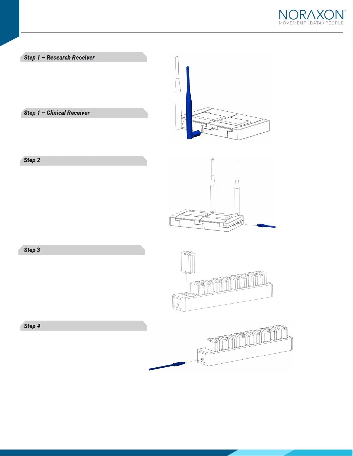
2 Install the Hardware
Step 1 – Research Receiver
Screw on the antenna (ANT3) to the antenna
connector located on the rear of the
myoMOTION Receiver (680). If the antenna is
already attached, check that it is securely
tightened.
Step 1 – Clinical Receiver
Insert the receiver into an availa le USB port
on your computer. (not pictured) Skip forward
to Step 3.
Step 2
Insert the mating (smaller) end of the USB
ca le (CBL17) into the USB connector on the
side of the receiver.
Insert the opposite end of the USB ca le into
an availa le USB port on the computer.
Step 3
Place Sensors in the Charging Station.
Step 4
For charging the sensors, insert the power
supply (PSU1) arrel connector into the jack of
the Sensor Charging Station (613).
myoMOTION Quick Start Guide
4
(Rev B)
3 Installing the Companion Software myoResearch™ 3
To utilize the full functionality of the Ultium EMG system, and ensure the system has updated drivers, Noraxon’s
myoResearch 3 needs to e installed on the computer.
The myoMOTION Receiver requires the Noraxon USB device driver which is pre-installed y the MR3 software installation.
It is also availa le in the Downloads Section of the Noraxon we site.
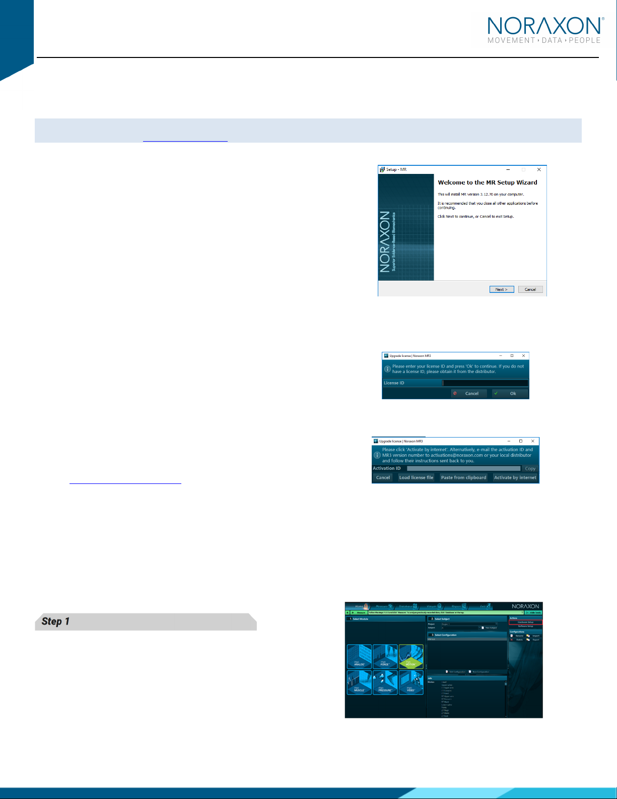
3.1 Software Installation
Within the package the myoMOTION System was shipped in, there is a
USB flash drive containing the latest myoResearch 3 software.
1. Insert the MR3 USB flash drive into the PC
2. A menu will automatically pop up
3. Click on the Noraxon installation file and follow the Wizard’s
instructions
3.2 Acti ating the Software
The installed companion software must e activated efore unrestricted use is possi le.
1. Open MR3
2. A dialog ox will indicate how many more times MR3 can e
opened
3. Click on “Activate”
4. Enter the License ID provided on your USB flash drive and
press “OK”
5. If you have an internet connection, click Activate y Internet
for immediate activation
6. Alternatively, email the provided activation ID to
activation@Noraxon.com Noraxon Support will email or
respond y phone with the Activation Code. Enter the
provided Activation Code to remove any restrictions on use.
4 Configuring the Hardware
Before the myoMOTION system can e used, the device software settings must e configured to recognize the different
components that make up the system. Follow the elow instructions to update the receiver firmware, sensor firmware, and
populate sensors to prepare for a data collection.
Step 1
Open MR3, typically listed under Noraxon -> R3
Click on the Hardware Setup
Hardware SetupHardware Setup
Hardware Setup utton in the upper right-hand
corner.

myoMOTION Quick Start Guide
5
(Rev B)
Step 2
Select the myoMOTION icon, within the ‘New Device
‘New Device‘New Device
‘New Device’
’’
’
column, and click on the Insert
InsertInsert
Insert utton.
Make sure the Receiver is attached to the USB port of
the computer.
Step 3
The
myoMOTION Settings dialog will appear as shown.
Input the serial num ers of your
myoMOTION IMUs into
Body Model Sensors
list according to the locations you
will put the sensors on the ody.
Step 4
Within the
Device Settings
Device SettingsDevice Settings
Device Settings ta , select the desired
collection Sampling Rate.
Select a RF network from the RF network list. In most
cases, the default “A” will work. However, if using
multiple
myoMOTION systems, each system must e
placed on separate networks to avoid interference that
may cause data loss or other issues.
If using
MyoSync, check the Use Noraxon MyoSync
check ox.
Check
Accel. Data
Accel. DataAccel. Data
Accel. Data if you wish to include acceleration
data in your measurement.
Select
Ok
OkOk
Ok when finished.
5 Attaching the Sensors
Before performing a recording, decide which ody segments will e included in the recording. The sensors can e attached
with the provided fixation straps. For fast or impact related movements, we recommend additional fixation of the sensors
with the use of elastic self-adhesive tape.
Sensor configuration, placement, and fixation est practices are further detailed and explained in the myoMOTION
Hardware User Manual. What is listed here is only a summary.

myoMOTION Quick Start Guide
6
(Rev B)
5.1 Sensor Placement Locations
5.2 Sensor Placement Orientation
Sensors must e placed so the Noraxon logo is facing away from the su ject.
The positive x-coordinate on the sensor la el should have a superior orientation (i.e. up to the sky/ceiling) for the
trunk, head, and pelvis. The lim segments sensors should have the positive x-coordinate in line with a proximal
orientation (i.e. towards the proximal joint along the long axis of the one segment).
Exception: For the foot sensor, the X-coordinate points distally (to the toes).
Head
HeadHead
Head
Middle of the ack of the head
U
UU
Upper
pper pper
pper
Thoracic
ThoracicThoracic
Thoracic
Below C7 in line with the spinal column, ut high enough to not
e affected y upper trapezius muscle movement
Lower
Lower Lower
Lower
Thoracic
ThoracicThoracic
Thoracic
In line with the spinal column at L1/T12. Strap elt will e
positioned on lower ri s on the front side of the ody.
Pelvic
PelvicPelvic
Pelvic
Body area of sacrum
Upper
Upper Upper
Upper
Arm
ArmArm
Arm
Midway etween the shoulder and el ow joints, lateral to the
one axis
Forearm
ForearmForearm
Forearm
Posterior and distal, where there is a low amount of muscle
tissue
Hand
HandHand
Hand
Dorsal
Thigh
ThighThigh
Thigh
Frontal and distal half, where there is a lower amount of muscle
displacement during motion
Shank
ShankShank
Shank
Front and slightly medial to e placed along the ti ia
Foot
FootFoot
Foot
Upper foot, slightly elow the ankle

myoMOTION Quick Start Guide
7
(Rev B)
6 Recording a Measurement
Step 1
Within the Home
HomeHome
Home screen click the myoMOTION module
icon.
Create a New Su ject.
New Su ject.New Su ject.
New Su ject.
Note: Defining the height for the su ject is important
since the software uses su ject height in its algorithm to
compute one lengths and create an accurate avatar
while recording and later viewing a record
Select New Configuration.
New Configuration.New Configuration.
New Configuration.
Step 2
Insert the devices to e used for the measurement into
the configuration y dragging a device in the list of
Availa le Devices
Availa le DevicesAvaila le Devices
Availa le Devices
to the
Devices in your configuration
Devices in your configuration Devices in your configuration
Devices in your configuration
window
windowwindow
window.
Select the desired ody segments to include in the
measurement configuration. Deselect the ody segments
you do not wish to include in the measurement. The
example image depicts what is seen for a full ody
MyoMotion set up.
Step 3
Continue to the next step y selecting Measure
MeasureMeasure
Measure.
A sensor activation dialogue will appear on the next
window. After approximately 20 seconds, the time
needed to activate the sensors, the full measurement
screen will appear.
Step 4
In the right-hand tool ar, select the desired cali ration
method.
Ensure sure the su ject is in the cali ration position and
is prepared to hold the cali ration position for 20 seconds
during the cali ration procedure.

myoMOTION Quick Start Guide
8
(Rev B)
Step 5
Select Cali ration.
Cali ration.Cali ration.
Cali ration. Monitor the su ject to confirm the
cali ration position was held for 20 seconds after clicking
Cali ration
Cali rationCali ration
Cali ration.
Step 6
After performing your cali rations and selecting a
correction mode (if desired), select Record
RecordRecord
Record.
Record your signal ased on predetermined protocols.
After performing desired movements in the record, click
Stop
StopStop
Stop and Save
SaveSave
Save.
Chose Discard & measure again
Discard & measure againDiscard & measure again
Discard & measure again or Save
SaveSave
Save after typing your
chosen record name.
7 Viewing a Record
To view a previously recorded record, select the Data ase
Data aseData ase
Data ase ta . Records are organized y Project
ProjectProject
Project and Su ject
Su jectSu ject
Su ject name. Dou le
click on the record of interest to open the record.
8 Further Use Features of MR3
There are many additional features uilt within MR3. Such as:
Magnetic correction modes (including treadmill mode)
Anti-wo le mode
Trajectories
Motion- ased contact detection
Cali ration modes
Customized reporting
Exporting (and importing) of data
To learn more a out the features availa le to you through the system(s) you have purchased, refer to the
MyoResearch User Manual and the corresponding Hardware User Manual for this device (P-6808).
Other manuals for Ultium Motion
2
This manual suits for next models
1
Table of contents
Popular Measuring Instrument manuals by other brands

Tenma
Tenma TEN01073 quick start guide

Sargon
Sargon Prospector instruction manual

SATO KEIRYOKI
SATO KEIRYOKI SK-610PH-II instruction manual

JCM Load Monitoring
JCM Load Monitoring ALRS2 User instructions

General
General DIGITAL POCKET WEATHERMAN SAM700BAR operating instructions

TFA
TFA 30.5027 instruction manual


Martini Instruments
Martini Instruments pH 55 user manual

kellermann
kellermann BL 1000 LED installation instructions

steute
steute RF 96 BU SW868-NET-LDS Mounting and wiring instructions

Olympus
Olympus OMCL-AC240TS-R3 user manual

JDS Uniphase
JDS Uniphase MP Series user manual

Team Electronic
Team Electronic SWR-1180-P Operation manual