Noraxon Ultium EMG System User manual
Ultium Footswitch SmartLead User Manual
1
(Rev C May 2019)
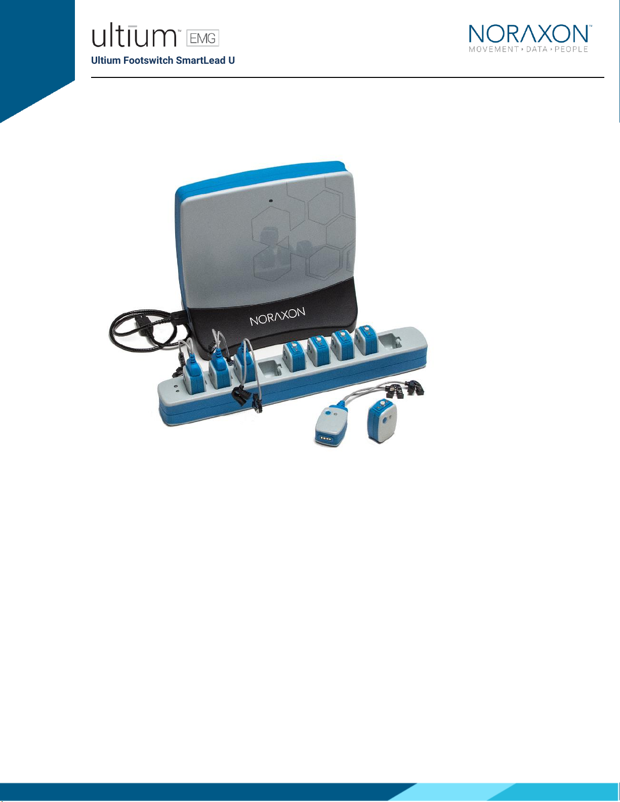
Ultium™ EMG System
Footswitch
SmartLead User Manual

Ultium Footswitch SmartLead User Manual
2
(Rev C May 2019)
1Table of Contents
1Table of Contents ............................................................................................................................................... 2
2Introduction.......................................................................................................................................................... 5
2.1 Brief Description........................................................................................................................................5
2.2Contraindications......................................................................................................................................5
3Definitions ............................................................................................................................................................ 6
3.1 Graphic Symbols and Meaning.............................................................................................................. 6
3.2 Glossary of Terms ....................................................................................................................................6
4Identification........................................................................................................................................................ 7
4.1 Model Designation....................................................................................................................................7
4.2 Product Versions and Configurations................................................................................................... 7
5General Warnings and Cautions ...................................................................................................................... 8
5.1 Risks and Benefits ....................................................................................................................................8
5.2 Safety Information Summary ................................................................................................................. 8
6Getting Started .................................................................................................................................................... 9
6.1 Quick Start Guides ....................................................................................................................................9
7Preparing the Product for Use........................................................................................................................10
7.1 Unpacking and Component Identification .........................................................................................10
7.2 Component Inputs, Outputs and Indicators ......................................................................................11
7.3 Component Interconnections...............................................................................................................12
7.4 Device Communication (Driver) Software Installation ....................................................................13
7.5 Companion Software Installation ........................................................................................................14
7.6 Companion Software Configuration ...................................................................................................14
8Pre-Use Check ...................................................................................................................................................19
8.1 Normal Appearance of Signals ............................................................................................................19
9Operating Instructions .....................................................................................................................................21
9.1 Safety Information Summary ...............................................................................................................21
9.2 Attaching the Sensor to a Patient or Subject ....................................................................................21
9.3 Normal Functions with Interface to a PC ...........................................................................................23
9.4 Exceptional Functions/Situations (error messages) .......................................................................23
9.5 Shutdown after Use................................................................................................................................23
9.6 Storage and Protecting Between Usages ..........................................................................................23
10 Cleaning ........................................................................................................................................................24
10.1 Safety Precautions When Cleaning .....................................................................................................24
10.2 Cleaning by Users ...................................................................................................................................24
11 Maintenance.................................................................................................................................................25
11.1 Device Software (firmware) updates ..................................................................................................25

Ultium Footswitch SmartLead User Manual
3
(Rev C May 2019)
11.2 Maintenance by Qualified Individuals .................................................................................................25
11.3 Companion Software Updates.............................................................................................................25
11.4 Attention ...................................................................................................................................................25
12 Troubleshooting ..........................................................................................................................................26
12.1 Website Link to FAQ ...............................................................................................................................26
13 Service and Repair ......................................................................................................................................27
13.1 Warranty Information.............................................................................................................................27
13.2 Submitting Technical Support Requests............................................................................................27
13.3 Returning Equipment .............................................................................................................................27
14 Spare Parts and Consumables .................................................................................................................28
14.1 Consumable Items .................................................................................................................................28
14.2 Replaceable Items ..................................................................................................................................28
15 Specifications of the Product....................................................................................................................29
15.1 Expected Useful Lifetime ......................................................................................................................29
15.2 Technical Specifications .......................................................................................................................29
15.3 Environmental Conditions for Storage and Transport.....................................................................29
16 Appendices...................................................................................................................................................30
16.1 Appendix A –FSR Usage Tips..............................................................................................................30
16.2 Appendix B –Insole measurements...................................................................................................32
16.3 Appendix C –Footswitch SmartLead Sensitivity ..............................................................................33
Ultium Footswitch SmartLead User Manual
4
(Rev C May 2019)
M- Manufacturer:
Noraxon U.S.A. Inc.
15770 North Greenway-Hayden Loop, Suite 100
Scottsdale, AZ 85260
Tel: (480) 443-3413
Fax: (480) 443-4327
Email: [email protected]
Web Site: www.noraxon.com
P- Authorized European Representative:
EC
REP
Advena Limited, Tower Business Centre, 2nd Flr., Tower Street, Swatar,
BKR 4013 Malta
Website: http://www.advenamedical.com
No part of this document may be copied, photographed, reproduced, translated, or reduced to any
electronic medium or machine-readable form without prior written consent of Noraxon U.S.A. Inc.
Noraxon and myoRESEARCH are registered trademarks and the Noraxon logo, myoANALOG, myoFORCE, myoMETRICS, myoMOTION,
myoMUSCLE, myoPRESSURE, myoVIDEO, myoSYNC, NiNOX, TRUsync and Ultium are common-law trademarks of Noraxon U.S.A., Inc. All other
trademarks are the property of their respective owners. ©2018, all rights reserved.
CE Mark: This symbol indicates the clearance to
market this product in the European Community.

Ultium Footswitch SmartLead User Manual
5
(Rev C May 2019)
2Introduction
2.1 Brief Description
The foot contact sensor lead consists of 4 FSR (force sensitive resistor) switch sensors which consist
of a thin circular film pad that is easy to attach. They can be mounted on the heel and the toe or
metatarsal region. It is designed for quick and easy use in clinical gait analysis. The Footswitch
SmartLead works with Noraxon Ultium EMG system as an accessory to the Ultium EMG Sensor (#810).
The Footswitch SmartLead has universal functionality covering easy and quick to use setups for
clinical gait screening, running and jump testing. If damage occurs due to heavy impact or shear forces
(running/jumping), broken sensors are easily replaced. The special connector allows easy replacement
but keeps the sensor from falling out during testing.
The Footswitch SmartLead is also compatible with Noraxon Footswitch insoles. The insole has a
separation of forefoot and back foot region. The benefit is the speed of set-up and ease of use - a
perfect tool for clinicians. The sole can be ordered as an accessory or in place of the single FSR-sensor
leads.
The insoles have 4 active pressure sensing areas. The threshold pressure required to initiate an off-to-
on response of the 4 areas can be adjusted by the user. Thus, individuals of various body weight can be
accommodated by adjustment of the insole sensitivity.
2.2 Contraindications
Use of the Ultium system is contra-indicated in individuals who have implanted pacemakers.
Ultium Footswitch SmartLead User Manual
6
(Rev C May 2019)
3Definitions
3.1 Graphic Symbols and Meaning
The following international icons and symbols may be found on the Footswitch SmartLead enclosures
and in this user manual. Their meaning is described below.
Read material in the Instruction Manual wherever this symbol
appears.
3.2 Glossary of Terms
Ultium Sensor -- A small individual radio transmitter typically worn on the body used to measure and
transmit bio-potential signals (such as EMG) or motion related signals (such as acceleration). The
Ultium Systems can accommodate up to 16 body worn Ultium Sensors in one network. Two Ultium
Systems may be used in parallel, on separate RF networks, to accommodate up to 32 body worn
sensors.
Ultium SmartLead –Refers to different data collection modalities. Each SmartLead measures a given
type of physical parameter. Different SmartLeads can be combined in the same Ultium network. The
most common Ultium SmartLead is EMG. Examples of other types include Accelerometers,
Goniometers and Force sensors.
Ultium Serial Number –A unique five-character tag used to identify each Ultium Sensor or Ultium
Smartlead. The members of any Ultium network are determined by their serial numbers. Also, Ultium
Sensor Types are grouped into a predefined range of serial numbers. Thus, by serial number the Ultium
system can automatically determine the type of signal parameter being transmitted from any Ultium
Sensor or Ultium SmartLead in the network.
Multi-Channel Sensor –Certain Ultium Sensor Types provide more than one signal. An example is a 3-D
Accelerometer that provides acceleration data for the x, y and z directions.
Ultium Footswitch SmartLead User Manual
7
(Rev C May 2019)
4Identification
4.1 Model Designation
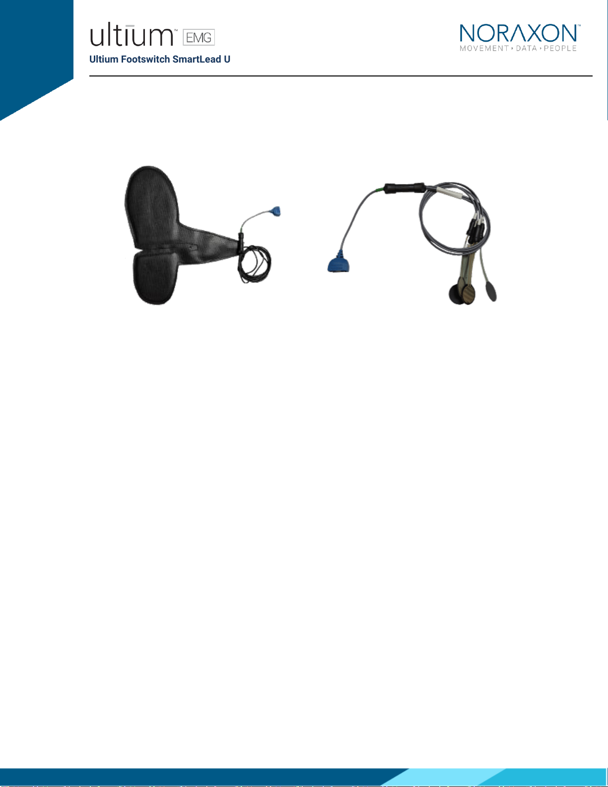
Model 802 Footswitch Smartlead with Part# 085F_ insole (left) and Part# FSA1 Footswitch sensor
assembly (right)
4.2 Product Versions and Configurations
The model 802 Footswitch SmartLeads must be utilized in conjunction with the Ultium EMG Sensor
(Part# 810) and the Ultium Receiver (Part #880).
For additional equipment details refer to Section 9 of this manual.
As the Noraxon Systems require software to perform its function, the equipment is offered in
combination with the following computer program packages:
Model #402 MR3 myoMuscle Module

Ultium Footswitch SmartLead User Manual
8
(Rev C May 2019)
5General Warnings and Cautions
5.1 Risks and Benefits
There is no identified risk of physical harm or injury with use of the Footswitch SmartLead. The benefit
provided by use of the device is the provision of objective measures to assess the severity of
pathological human movement conditions and gauge any subsequent improvement offered by therapy,
training, prosthetic alterations or ergonomic design changes.
5.2 Safety Information Summary
Cautions
•Never use the Footswitch on a person with an implanted pacemaker
•Never operate the Footswitch within 1 meter of any critical medical device
Warnings
•Do not immerse the Ultium sensors in any water or liquid
•Do not use the Ultium equipment on individuals undergoing MRI, Electro Surgery or
Defibrillation
•The Footswitch product produces results that are informative, not diagnostic. Qualified
individuals must interpret the results
Attention
•The operator must be familiar with typical characteristics of the signals acquired by the
Footswitch and be able to detect anomalies that could interfere with proper interpretation.

Ultium Footswitch SmartLead User Manual
9
(Rev C May 2019)
6Getting Started
6.1 Quick Start Guides
Please see the hardware manual for the appropriate EMG system.
P-880: Ultium hardware user manual

Ultium Footswitch SmartLead User Manual
10
(Rev C May 2019)
7Preparing the Product for Use
7.1 Unpacking and Component Identification
Footswitch SmartLead (Part #802)
Footswitch FSR SmartLead Sensor Assembly
(Part #FSA1)
Footswitch Insole SmartLead (Part #085F_)
Force Sensitive Resistors (Part #FSR1)
Ultium Footswitch SmartLead User Manual
11
(Rev C May 2019)
Strap 18 inch (Part #ES1)
Additional contents not illustrated
Footswitch User Manual (part #802A) This document
If additional accessories have been included please see Section 9, Accessories for component
identification.
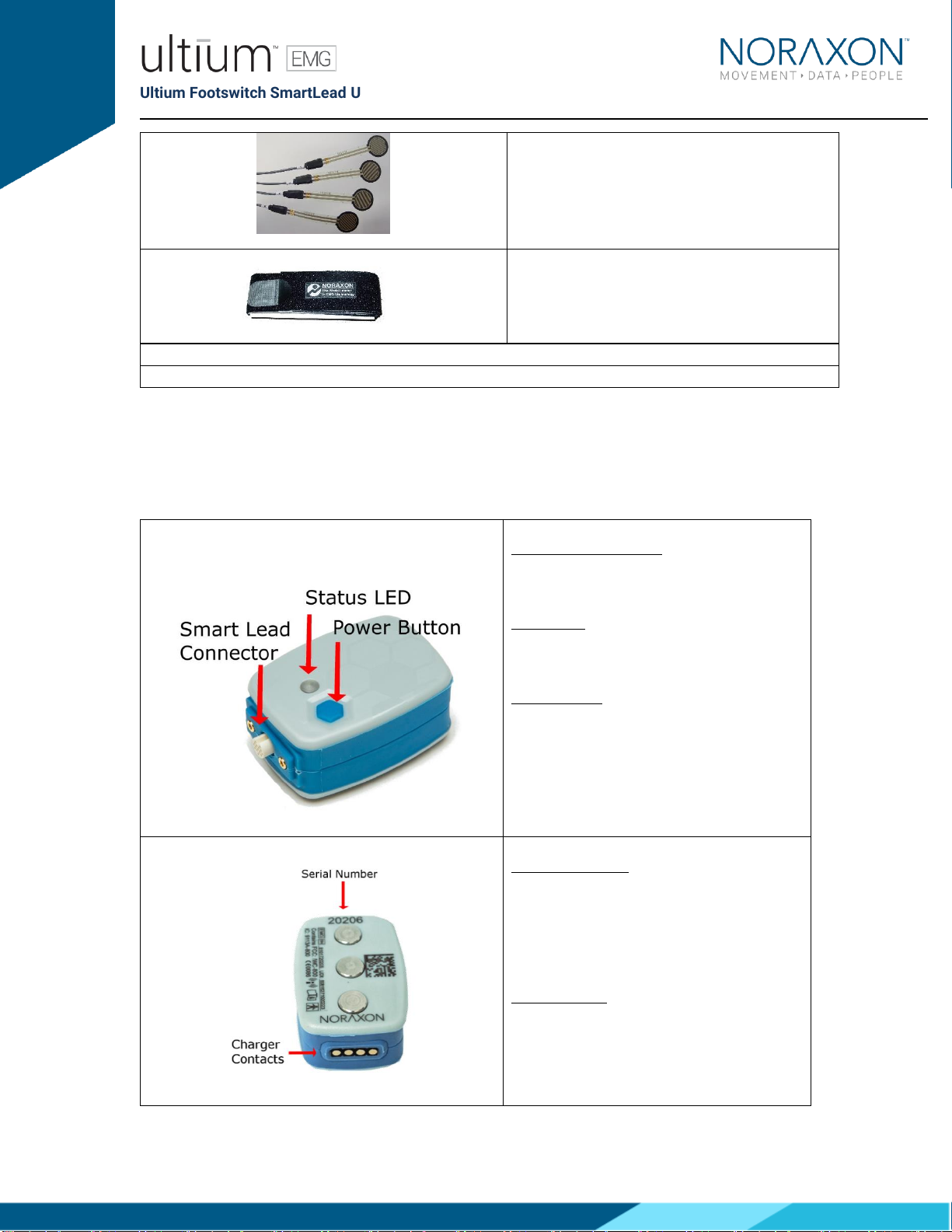
7.2 Component Inputs, Outputs and Indicators
1 EMG Sensor (front and top edge)
Smart Lead Connector –Connector for
smart leads to change function of EMG
sensor.
Status LED –Sensor operational indicator
flashes green when measuring. Solid
Yellow when charging.
Power Button –Power the sensor On/Off.
Hold for 3+ seconds for a hard reset.
2 EMG Sensor (back and bottom edge)
Charger Contacts –Sensor battery is
charged and sensor data is exchanged
through these points.
Serial Number –Unique 5-character serial
number which identifies each EMG sensor.

Ultium Footswitch SmartLead User Manual
12
(Rev C May 2019)
3 Footswitch SmartLead
Serial Number: Unique 5-character serial
number which identifies each SmartLead.
7.3 Component Interconnections
Step 1A
Connect the Footswitch connector
(Male 5-pin connector) with the
FSA1 connector (Female 5-pin
connector)
Step 1B
Connect the Footswitch connector
(Male 5-pin connector) with the
Ultium Insole connector (Female 5-
pin connector)
Step 2A
Connect the FSA1 Leads to the FSR
sensors (FSR1).

Ultium Footswitch SmartLead User Manual
13
(Rev C May 2019)
7.4 Device Communication (Driver) Software Installation
No driver installation is needed. The Ultium Receiver communicates over the USB port.

Ultium Footswitch SmartLead User Manual
14
(Rev C May 2019)
7.5 Companion Software Installation
The Footswitch SmartLead is compatible with several different software programs. Identify the
companion software that accompanied the equipment (MR3) and follow the appropriate instructions
given next.
7.5.1 MR3 Installation
1. Insert the MR3 feature map into the PC
2. A menu will automatically pop up
3. Click on “Install MR3” and follow the Wizard’s instructions
4. Double click on the icon to start the MR3 software
7.6 Companion Software Configuration
Before the Footswitch can be used with the Noraxon Ultium system, the companion software must be
configured to recognize the different components that make up the system. Refer to the Ultium
system’s hardware manual for instructions on the software module (MR3 myoMUSCLE) supplied with
the Noraxon system. For specific settings for the Footswitch SmartLead see below:
When assigned to a channel using the serial number, the software should automatically detect the
sensor as a Footswitch SmartLead:

Ultium Footswitch SmartLead User Manual
15
(Rev C May 2019)
7.6.1 MR3 Configuration
Step 1
Enter the Hardware Setup
screen and setup the Noraxon
EMG system in accordance
with its provided hardware
manual.
Step 2a
Click ‘Detect Sensors in
Charger’ (All sensors which you
would like to use must be in
the charger) –this will add the
SmartLead(s) to the list of
sensors (only if the unique
SmartLead is connected to
their corresponding sensor).
If the unique SmartLead (ex:
Footswitch) is not connected
to the corresponding sensor
during detection, MR3 will
assume you are using the
sensor to collect EMG data.
Click OK.
Ultium Footswitch SmartLead User Manual
16
(Rev C May 2019)
Troubleshooting: If the indicator light is never green, double check
that you are using the correct sized insole (should sit flat on the
bottom of the shoe, covering the whole surface, with no overlap of
the heel portion with the toe portion). Repositioning will likely solve
this issue.
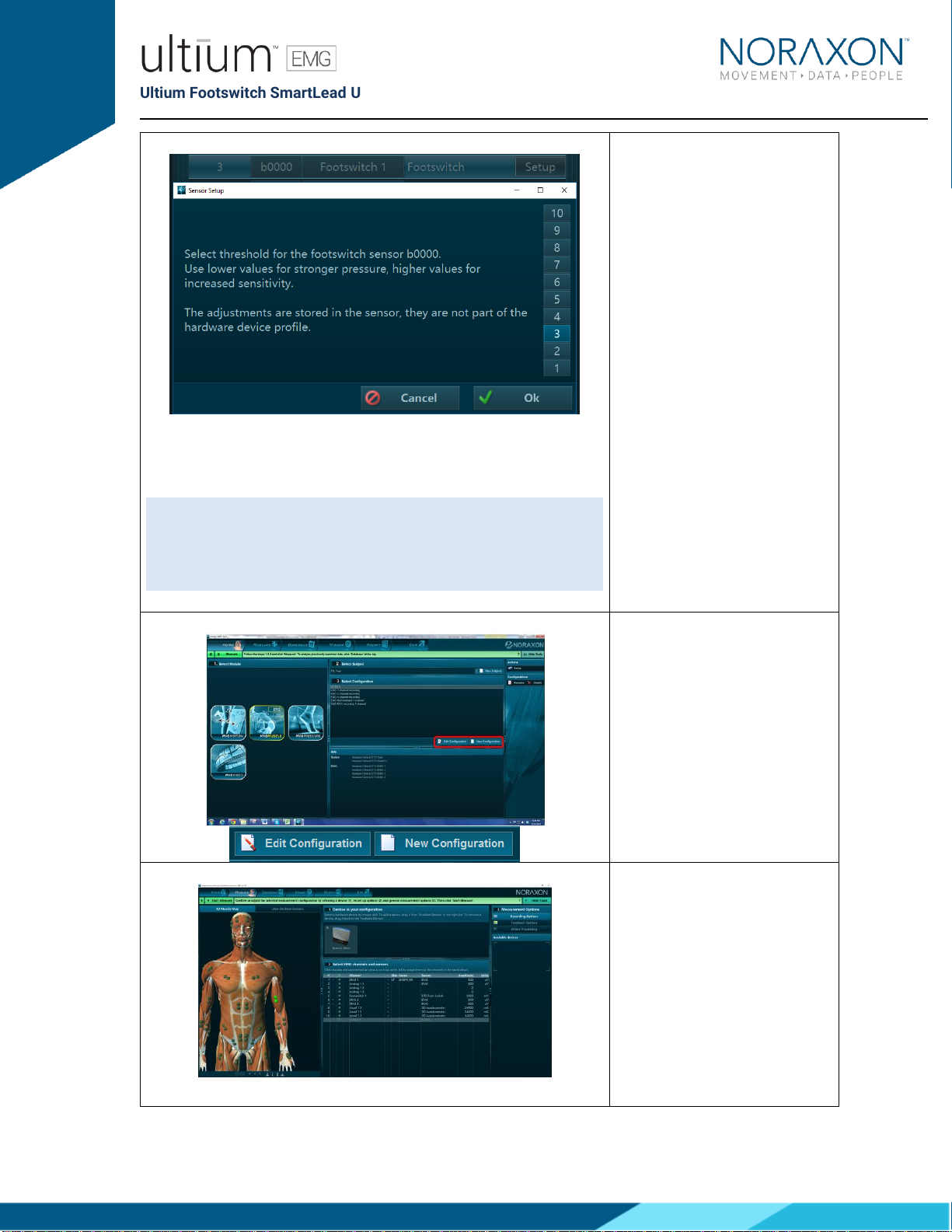
Step 2b
Click on ‘Setup’, next to the
Footswitch inside of Hardware
Setup. The numerical values
correspond to the level of
pressure (threshold) needed to
activate the Footswitch’s
internal pressure sensors.
Have the individual wearing the
insole stand upright with their
feet shoulder-width apart and
pointing straight ahead. If all
four sensors within the insole
are activated (heel, M5, M1,
and toe) –the indicator light on
the Ultium sensor in which the
SmartLead is connected will
turn green. To have the
greatest level of sensitivity, use
the lowest number in which the
indicator light remains green.
Step 3
Once back in the Home screen,
choose to create a new or edit
an existing configuration.
Step 4
In the configuration setup
screen, insert the Ultium
system into the Devices
section.
It is recommended that you
redetect sensors in the
hardware configuration every
time the SmartLeads are
removed from the Ultium
Ultium Footswitch SmartLead User Manual
17
(Rev C May 2019)
sensor (redetection is
necessary to revert to the use
of the sensor’s EMG
functionality). This will prevent
configuration errors leading to
the inability to collect a
measurement. If an error
message pops up when
starting a measure, and you are
using SmartLeads, this is a
good first troubleshooting step
(1. Redetect sensors in
hardware set-up; 2. Double
check the configuration).
* See Find My Sensor section
below
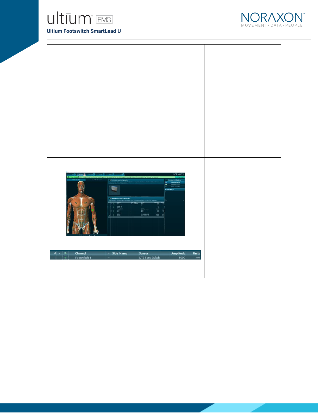
Step 5
Once the Ultium system is
inserted, the muscle map will
appear to the left, and the EMG
channels and sensors will
appear below. The Footswitch
SmartLead should
automatically appear, as
detected by the Ultium system
(if it does not –refer to step
2a).
To select the Footswitch for
use in a recording, check the
box next to the Footswitch
channel to be recorded.
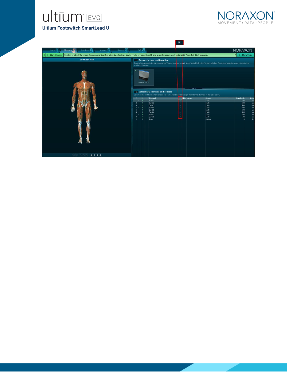
7.6.2 Find My Sensor Feature
Find my Sensor allows the user to quickly locate a specified Ultium sensor while creating/editing a MR3
configuration (refer to section 7 for guidance on how to create or edit a configuration). If one of the
stars (refer to the figure below) is clicked, the corresponding sensor will repeatedly blink light purple in
bursts of 3. If the topmost star is clicked, every sensor that is currently in the configuration will execute
the same blinking pattern.
Ultium Footswitch SmartLead User Manual
18
(Rev C May 2019)
Ultium Footswitch SmartLead User Manual
19
(Rev C May 2019)
8Pre-Use Check
8.1 Normal Appearance of Signals
The sensor’s STATUS LED provides a means of communicating its operational state. In the idle state,
the STATUS LED will flash blue at a low, once per second rate. When the sensor is actively measuring a
signal, the STATUS LED will flash recognizably faster (green).
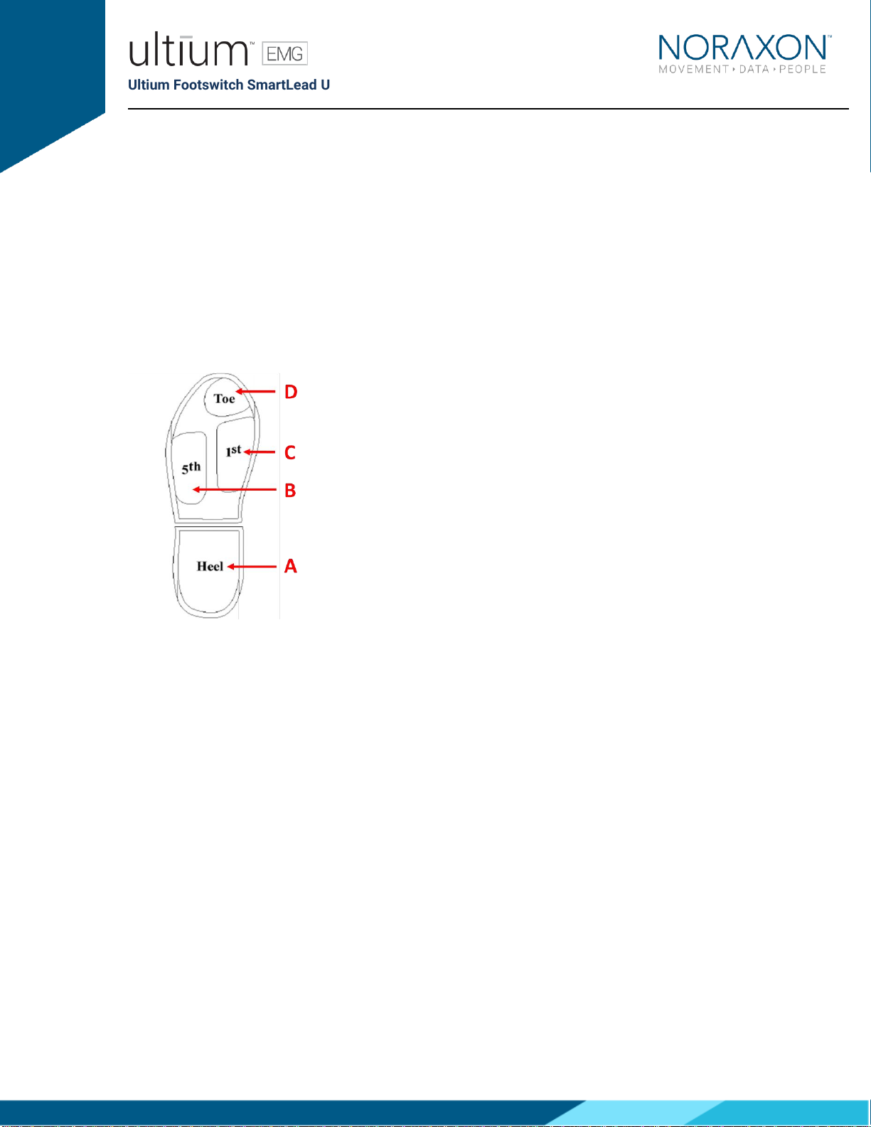
Quick Testing:
To ensure that the Footswitch SmartLead is measuring properly when connected to the Ultium Sensor,
firmly press on the center of each of the four regions (heel, 5th metatarsal, 1st metatarsal, and toe)
shown below:
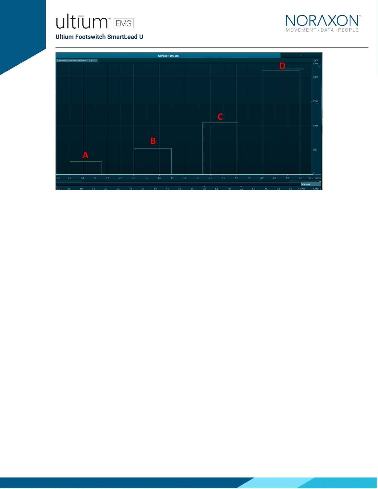
In the example below, the heel (A), 5th metatarsal (B), 1st metatarsal (C) and toe (D) regions are pressed
in order. Ensure that the voltage outputs are as follows:
•Heel - 0.266V
•M5 - 0.533V
•M1 - 1.066V
•Toe - 2.133V
Ultium Footswitch SmartLead User Manual
20
(Rev C May 2019)
A similar protocol can be used when testing the FSRs. This will ensure that each FSR is functioning
properly and help identify their corresponding placement on the foot.
Other manuals for Ultium EMG System
5
Table of contents
Popular Medical Equipment manuals by other brands


Getinge
Getinge Arjohuntleigh Nimbus 3 Professional Instructions for use

Mettler Electronics
Mettler Electronics Sonicator 730 Maintenance manual

Pressalit Care
Pressalit Care R1100 Mounting instruction

Denas MS
Denas MS DENAS-T operating manual

bort medical
bort medical ActiveColor quick guide

AccuVein
AccuVein AV400 user manual


