manuals.online logo
Brands
  1. Home
  2. •
  3. Brands
  4. •
  5. novotechnik
  6. •
  7. Transducer
  8. •
  9. novotechnik Z-TF1-PO1 User manual

novotechnik Z-TF1-PO1 User manual

Page 1
1General description 2
2Safety instructions 2
2.1 Intended conditions of use 2
2.2 Installation & startup 2
2.3 Check connections 2
2.4 Turning on the system 2
2.5 Check measured values 2
2.6 Check functionality 2
2.7 Failure malfunction 2
3Electrical data 3
4Instructions for Wiring 3
5Mounting and installation 4
5.1 Transducer 4
5.2 Position marker 5
5.2.1 Z-TF1-P01 5
5.2.2 Z-TF1-P02 5
5.2.3 Z-TF1-P03 5
6
Interfaces and Connection Assignment
6
6.1 Analog outputs 6
6.2 SSI interface 6
6.3 IO-Link interface 7
6.4 CANopen interface 7
6.5 Cable break detection 8
7Teach-In function 8
8LED Functionality 10
9Error conditions 10
10 Optional accessories 11
11 Ordering code 11
12 Product identication 11
1 概要 2
2安全上の注意 2
2.1 使用目的 2
2.2 インストールと起動 2
2.3 接続を確認する 2
2.4 システムの電源を入れる 2
2.5 測定値を確認する 2
2.6 機能を確認する 2
2.7 故障誤動作 2
3電気的データ 3
4配線手順 3
5取付とインストール 4
5.1 トランスデューサー 4
5.2 ポジションマーカー 5
5.2.1 Z-TF1-P01 5
5.2.2 Z-TF1-P02 5
5.2.3 Z-TF1-P03 5
6
インターフェースと接続の割り当て
6
6.1 アナログ出力 6
6.2 SSI インターフェース 6
6.3 IO-Link インターフェース 7
6.4 CANopen インターフェース 7
6.5 ケーブル断線検出 8
7ティーチイン機能 8
8LED 機能 10
9エラー状態 10
10 オプションのアクセサリ 11
11 注文コード 11
12 商品の識別 11
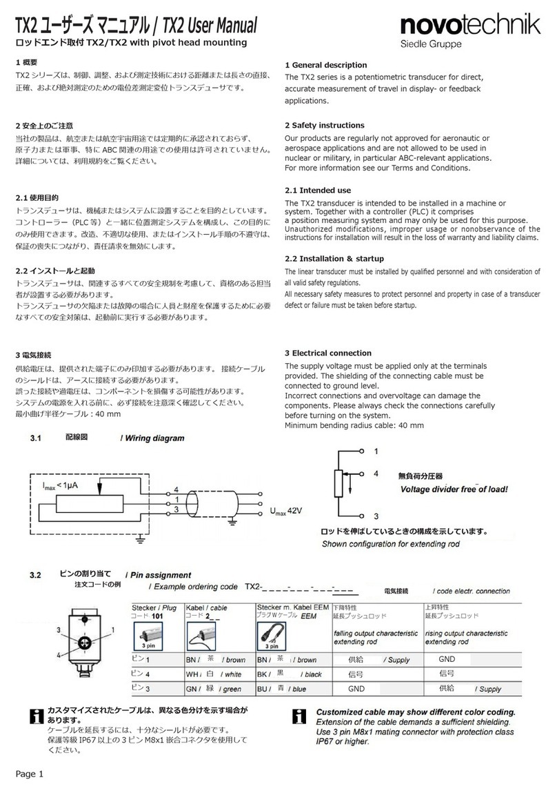
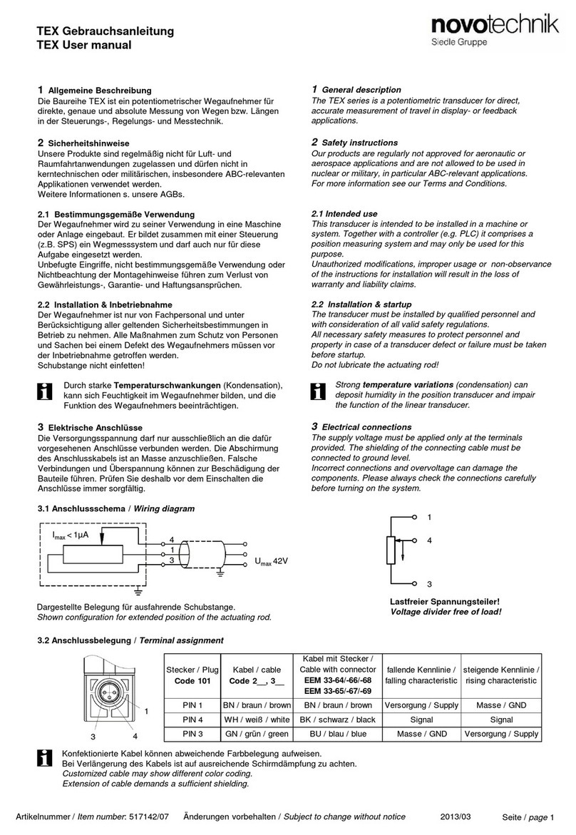
TF1 ユーザーズマニュアル / TF1 User manual
1 General description
The TF1 series is an inductive transducer for direct,
accurate measurement of travel in display- or feedback
applications.
2 Safety instructions
Our products are regularly not approved for aeronautic or
aerospace applications and are not allowed to be used in
nuclear or military, in particular ABC-relevant applications.
For more information see our Terms and Conditions.
2.1 Intended use
The transducer is intended to be installed in a machine or system. Together with a controller it
comprises a rotary position measuring system and may only be used for this purpose.
Unauthorized modifications, improper usage or non-observance of the instructions for
installation will result in the loss of warranty and liability claims.
2.2 Installation & startup
The transducer must be installed only by qualified personnel in consideration of all
relevant safety regulations.
All necessary safety measures to protect personnel and property in case of a transducer
defect or failure must be taken before startup.
    Only very strong magnetic elds in the immediate
proximity of the position marker can cause incorrect signals!
2.3 Check connections
Improper connections and overvoltage can damage the transducer.
Check the connections always carefully before turning-on system.
     Potential dierences between supply voltage
     GND and signal GND must be avoided.
     With dierent potentials between supply voltage
     GND and signal GND the transducer can be destroyed!
2.4 Turning on the system
   The system may execute uncontrolled movements during rst  
   turning-on mainly when the transducer is part of a control system
whose parameters have not yet been set. Therefore make sure that
hereof no dangers for personnel and property can result.
2.5 Check measured values
After replacement of a transducer, it is advisable to verify the output
values for start- and end position of the position marker in manual mode.
(Transducers are subject to modication or manufacturing tolerances)
2.6 Check functionality
The functionality of the transducer system and all its associated
components should be regularly checked and recorded.
2.7 Failure malfunction
If the transducer system doesn ‘t operate properly, it should be taken
out of service and protected against unauthorized use.
1 概要
TF1 シリーズは、制御、測定に用いられる高精度アブソリュートタイプの
誘導変位トランスデューサです。
2 安全上の注意
当社の製品は、航空または航空宇宙用途では定期的に承認されておらず、原
子力または軍事、特に ABC 関連の用途での使用は許可されていません。
詳細については、利用規約をご覧ください。
2.1 使用目的
トランスデューサは、機械またはシステムに設置することを目的としています。
コントローラー(PLC 等)と一緒に位置測定システムを構成し、この目的に
のみ使用できます。
改造、不適切な使用、またはインストール手順の不遵守は、
保証の喪失につながり、責任請求を無効にします。
2.2 インストールと起動
トランスデューサは、関連するすべての安全規制を考慮して、資格のある担当
者のみが設置する必要があります。
トランスデューサの欠陥または故障の場合に人員と財産を保護するために必要
なすべての安全対策は、起動前に実行する必要があります。
   ポジションマーカーのすぐ近くに非常に強い磁場があると、信号障害や
危険な状態を引き起こす可能性があります。
2.3 接続を確認する
不適切な接続と過電圧は、トランスデューサを損傷する可能性があります。
システムの電源を入れる前に、必ず接続を注意深く確認してください。
供給電圧 GND と信号 GND の電位差は避けてください。
供給電圧 GND と信号 GND の間の電位が異なると、
トランスデューサーが破壊される可能性があります。
2.4 システムの電源を入れる
   システムは、特にトランスデューサのパラメータがまだ設定されていな  
   い制御システムの一部である場合、最初の電源投入時に制御されていな
い動作を実行する場合があります。 したがって、これが人員や財産に危険が
及ばないようにしてください。
2.5 測定値を確認する
トランスデューサの交換後は、手動モードでポジションマーカーの開始位置と
終了位置の出力値を確認することをお勧めします。(トランスデューサは変更
または製造公差の対象となります)
2.6 機能を確認する
トランスデューサとそれに関連するすべてのコンポーネントの機能を定期的に
チェックしてください。
2.7 故障誤動作
トランスデューサが適切に動作しない場合は、使用を停止し、不正使用から保
護してください。
Page 2
TF1 ユーザーズマニュアル / TF1 User manual
Page 3
TF1 ユーザーズマニュアル / TF1 User manual
3 電気的データ / Electrical data
供給電圧 /Supply voltage: 24 VDC ( データシートも参照 /see also data sheet)
負荷 / Load R : ≥ 5 ㏀ 電圧出力 / voltage output
          ≤ 500Ω 電流出力 / current output
消費電力 /Power consumption: ≤ 2.4 無負荷 /without load
4 Instructions for Wiring
Note the following when making electrical connection:
System (supply voltage GND) and control cabinet (signal GND) must
be at the same potential.
To ensure the electromagnetic compatibility (EMC), the following
instructions must be strictly followed*:
• Transducer and controller must be connected by using a
shielded cable.
• Shielding: Copper lament braided, 85% coverage.
• On the controller side the cable shield must be grounded,i.e. be
connected with the protective earth conductor.
*) Sensors with IO-Link interface may be connected using
an unshielded cable. Max. cable length is 20 m.
     Elongation of the cable connection to more than 30 m  
     results in loss of CE compliance !
4 配線手順
電気接続を行うときは、次の点に注意してください:
システム(供給電圧 GND)と制御盤(信号 GND)は同じ電位でなければなり
ません。電磁両立性(EMC)を確保するには、次の指示に厳密に従う必要が
あります *: 
• トランスデューサーとコントローラーは、シールドケーブルを使用して接続
する必要があります。
• シールド:単一の銅線で作られた編組、85%の被覆率。
• コントローラー側では、ケーブルシールドを接地する必要があります。
つまり、保護アースに接続します。
*)IO-Link インターフェースを備えたセンサー場合は、シールドされていな
いケーブルを使用して接続できます。 最大 ケーブル長は 20m です。
 
 ケーブル接続を 30m 以上に延長すると、CE 承認が失われます。
供給電圧 GND/
信号 GND/
信号 /
供給電圧 Ub/
シールドケーブル /
保護アースに接続されたシールド(両側)/
電気接続 例えば M12 × 1 プラグコネクタ /
取付クランプ(絶縁)
保護アースに接続された機械ハウジング
供給電圧
24VDC
L
5 インストール / Installation
Page 4
TF1 ユーザーズマニュアル / TF1 User manual
5.1 トランスデューサ / Transducer
納品に含まれるもの:取り付けクランプ Z-46(ヘッドキャップネジ M5x20 を含む)
Included in delivery: mounting clamps Z-46 incl. head cap screws M5x20
注文コードの例
必要なアクセサリ :ポジションマーカー
取り付けクランプを使用した取り付けの代わり
に、トランスデューサーは、溝に挿入された M8
ナット(DIN 439、厚さ 4.0 mm)で固定できます。
最大締付 200 Ncm
取り付けクランプ
• フランジに取り付けないでください
 (ハウジングプロファイルのみに)
• いくつかの取り付けクランプ:等距離に配置
•
2 つの取り付けクランプ:相互の距離約ハウジングの長さの 2/3
Page 5
TF1 ユーザーズマニュアル / TF1 User manual
5.2 ポジションマーカー
ポジションマーカー(アクセサリ)は、プロファイル面から定義された距離に
設置します。トランスデューサの精度を確保するために、フローティングポジ
ションマーカーはプロファイル面と平行に設置する必要があります。
5.2 Position marker
The position marker (accessory) is installed at a dened distance to the
prole surface .
In order to ensure the accuracy of the transducer, the oating position
marker must be guided parallel to the prole surface.
5.2.1 Z-TF1-P01 P/N 400104343 フローティングポジションマーカー /oating position marker
電気的ゼロ点
電気的ゼロ点
ポジションマーカーは両方向に取付することが
できます。
動作距離 A    0…4mm *
公称距離     1.5mm
取付距離 B    49…53mm
許容横方向芯ずれ ± 2mm
*)温度での膨張挙動に注意してください
Working distance A   0…4 mm *
Nominal distance    1,5 mm
Mounting distance B   49 … 53 mm
Permitted lateral oset ± 2 mm
*)
Pay attention to expansion behaviour at temperature
動作距離 A
Working distance A
信号の変化
signal change
1.3 … 1.7 mm
なし /no
作動距離内の公称距離からの偏差
Deviation from nominal distance within
working distance
0...4mm
50mm
横方向の芯ずれ
Lateral oset
信号の変化
signal change
± 1mm
なし /no
± 2mm
50mm
±4mm
(動作範囲外)
(Outside the working range)
測定長寸法図 .B
Measuring length Dim. B
≤ 400 mm: 50 µm/mm
> 400 mm: > 50 µm/mm
5.2.2 Z-TF1-P02 P/N 400104344 アキシャルジョイント付きポジションマーカー / guided position marker with axial joint
5.2.3 Z-TF1-P03 P/N 400104345 アングルジョイント付きポジションマーカー / guided position marker with angle joint
電気的ゼロ点 電気的ゼロ点
電気的ゼロ点
ポジションマーカーは両方向に取付することが
できます。
ポジションマーカーは両方向に取付することが
できます。(5.2.2 を参照)
M5、10 深さ、回転 18°
M5、10 深さ、回転 18°
Page 6
TF1 ユーザーズマニュアル / TF1 User manual
6 インターフェースと接続の割り当て / Interfaces and Connection Assignment
プラグコード /
Plug Code 102
コネクターケーブル EEM/
connector w.cable EEM
信号電圧 /
Voltage Code 41_
信号電流 /
Current Code 42_
ピン 1/PIN 1
WH 白 / white 接続なし /do not
connect
4 … 20 mA
ピン 2/PIN 2 BN 茶 / brown 信号 GND/
Signal GND
信号 GND/
Signal GND
ピン 3/PIN 3 GN 緑 / green
接続なし /
do not connect
接続なし /
do not connect
ピン 4/PIN 4 YE 黄 / yellow  PROG_L * PROG_L *
ピン 5/PIN 5 GY 灰 / grey   0 … +10 VDC
接続なし /
do not connect
ピン 6/PIN 6 PK 桃 / pink 供給電圧 GND/
supply voltage GND
供給電圧 GND/
supply voltage GND
ピン 7/PIN 7 BU 青 / blue + 24 VDC + 24 VDC
ピン 8/PIN 8 RD 赤 / red PROG_H * PROG_H *
6.1 アナログ出力 / Analog Output
ノイズを最小限に抑えるための推奨測定帯域幅 / Recomm. measuring bandwidth for noise reduction < 100kHz
注文コードの例 /Example ordering code: 電圧出力 / Voltage output: TF1- _ _ _ _ - _ _ _ -41_ - 102 
注文コードの例 /Example ordering code: 電流出力 / Current output: TF1- _ _ _ _ - _ _ _ -42_ - 102
コネクターコード 102 の正面図
*)ティーチイン機能でのみ接続し、通常の操作では接続しないでください(第 9 章も参照)。
Connect only for Teach-In function, do not connect in normal operation (see also chapter 9).
6.2 SSI インターフェース / SSI Interface
注文コードの例 /Example ordering code: TF1- _ _ _ _ - _ _ _ -2_ _ - 102 
プラグコード /
Plug Code 102
コネクターケーブル EEM/
connector w.cable EEM
信号 SSI コード 2_ _/
Signal SSI Code 2_ _
ピン 1/PIN 1 WH 白 / white
CLK +
ピン 2/PIN 2 BN 茶 / brown DATA +
ピン 3/PIN 3 GN 緑 / green
CLK -
ピン 4/PIN 4 YE 黄 / yellow 
接続なし /
do not connect
ピン 5/PIN 5 GY 灰 / grey   DATA -
ピン 6/PIN 6 PK 桃 / pink GND
ピン 7/PIN 7 BU 青 / blue + 24 VDC
ピン 8/PIN 8 RD 赤 / red
接続なし /
do not connect
コネクターコード 102 の正面図
不適切な接続と過電圧は、トランスデューサーを損傷する可能性があります。
カスタマイズされたケーブルは異なる色分けを示す場合があります!
シールド付きツイストペアケーブル(STP)をお勧めします。
SSI グレー:エンコーディングには、位置および診断データ
(Data + E + W)が含まれます。
データレンジ
クロック
データ
タイムアウト時間 tm / Timeout time tm 20 µs 
クロック周波数 / clock frequency min. 60 kHz, max. 1500 kHz
コード出力信号 /
Code Output signal
分解能(LSB)/
Resolution (LSB)
TF1-_ _ _ _ -_ _ _ -221 / 221 / 227-_ _
1 µm
TF1-_ _ _ _ -_ _ _ -222 / 225 / 228-_ _ _ 5 µm
TF1-_ _ _ _ -_ _ _ -223 / 226 / 229-_ _ _ 10 µm
エラービット
  ワーニングビット
ケーブルの長さ /
Cable length[m]
< 3 < 10 < 50 < 100 < 200 < 400
クロック周波数 /
Clock frequency CLK [kHz]
< 1400 < 1000 < 600 < 350 < 200 < 100
最大 ケーブル長に応じた伝送速度
ビット
ビット
Page 7
TF1 ユーザーズマニュアル / TF1 User manual
プラグコード /
Plug Code 107
コネクターケーブル EEM/
connector w.cable EEM
信号 IO-Link/
Signal IO-Link
コード A_ _
ピン 1/PIN 1 BN 茶 / brown
+ 24 VDC (L+)
ピン 2/PIN 2 WH 白 / white 接続なし */
do not connect *
ピン 3/PIN 3 BU 青 / blue GND (L-)
ピン 4/PIN 4 BK 黒 / black  C/Q
6.3 IO-Link インターフェース
Example ordering code: TF1- _ _ _ _ - _ _ _ -A_ _ - 107
*)GND の代わりに / alternatively to GND
6.3.2 分解能(LSB)/ Resolution (LSB)
コード出力信号 /
Code Output signal
分解能(LSB)/
Resolution (LSB)
TF1-_ _ _ _ -_ _ _ -A3_-_ _ _
1 µm
TF1-_ _ _ _ -_ _ _ -A1_-_ _ _ 5 µm
6.3 IO-Link Interface
Example ordering code: TF1- _ _ _ _ - _ _ _ -A_ _ - 107
The description of IO-Link interface
(…IO-Link_Detail) and the device description le
(IODD) can be downloaded from
Novotechnik website, see Downloads/Operating
manuals
=> Click on TF1
IO-Link インターフェースの説明(…IO-Link_Detail)とデバイス説明ファイル(IODD)
は、Novotechnik の Web サイトからダウンロードできます。
ダウンロード / 操作マニュアルを参照してください
=> TF1 をクリックしてください。
6.3.1 ピン割り当て / Pin assignment
コネクターコード 107 の正面図
6.4 CANopen インターフェース
Example ordering code: TF1- _ _ _ _ - _ _ _ -6_ _ - 106
6.4 CANopen Interface
Example ordering code: TF1- _ _ _ _ - _ _ _ -6_ _ - 106
CANopen インターフェースの説明(…CANopen_Detail)と
電子データシート(EDS)は、Novotechnik の Web サイトから
ダウンロードできます。
ダウンロード / 操作マニュアルを参照
=> TF1 をクリックしてください。
The description of CANopen interface (…CANopen_Detail)
and the electronic data sheet (EDS) can be downloaded
from Novotechnik website,
see Downloads/Operating manuals
=> Click on TF1
6.4.1 ピン割り当て / Pin assignment
プラグコード /
Plug Code 106
コネクターケーブル EEM/
connector w.cable EEM
信号 CANopen/
Signal CANopen
コード 6_ _
ピン 1/PIN 1
CAN シールド /  shield * CAN シールド / shield
ピン 2/PIN 2 RD 赤 / red + 24 VDC
ピン 3/PIN 3 BK 黒 / black
GND
ピン 4/PIN 4 WH 白 / white
CAN high
ピン 5/PIN 5 BU 青  / Blue   CAN low
*)内部でハウジングに接続 / internally connected to housing
コネクターコード 106 の正面図
6.4.2 分解能(LSB)/ Resolution (LSB)
コード出力信号 /
Code Output signal
分解能(LSB)/
Resolution (LSB)
TF1-_ _ _ _ -_ _ _ -63_-_ _ _
1 µm
TF1-_ _ _ _ -_ _ _ -61_-_ _ _ 5 µm
44
55
Page 8
TF1 ユーザーズマニュアル / TF1 User manual
6.5 ケーブル断線検出 / Cable break detection
インターフェース /
Interface
コード /
Code
ケーブル断線時の出力 /
Output at cable
SSI TF1-_ _ _ _ -_ _ _-2_ _-102 接続なし /no communication
0 …10 V TF1-_ _ _ _ -_ _ _-41_-102 < 100 mV
4 … 20 mA TF1-_ _ _ _-_ _ _-42_-102 < 3.5 mA
IO-Link TF1-_ _ _ _-_ _ _-A_ _-107 接続なし /no communication
CANopen TF1-_ _ _ _-_ _ _-6_ _-106 接続なし /no communication
7 アナログモデルのティーチイン機能 7 Teach-In function for analog models
7.1 説明
カスタムの設定範囲を定義するために、アナログ出力を備えたトランスデュー
サ TF1 の開始位置および / または最終位置を追加で調整できます。
7.1 Description
Starting and/or final position of the transducer TF1 with
analog output can additional be adjusted, in order to dene
the setting range(s) custom-specic.
機械の操作中にティーチインをアクティブにしないでください。
ティーチインをアクティブにする前に、
マシンを停止する必要があります。
Do not activate Teach-In during machine operation.
Machine must be put out of operation before
activating Teach-In.
7.2 重要な詳細
プログラミング中に出力信号を監視するには、デジタル電圧計を使用します。
ティーチインの際は前述の項目 2 にあるように、関連するすべての安全規制を
考慮する必要があります。
最後にプログラムされた値は、電源をオフにした後でもメモリに保存されたままに
なります。
プログラミングには PROG_L と PROG_H を使用します。
ティーチインは、電源投入後 30 秒以内に開始する必要があります。
7.2 Important details
Use a digital volt meter to monitor output signal during
programming.
After Teach-In all relevant safety regulations as in item 2
mentioned must be considered.
The last programmed values remain stored in memory, even
after power-o.
Use PROG_L and PROG_H for programming.
The Teach-In must be started within 30 s after poweron.
ティーチイン手順内およびティーチインの完了後の記載された
プログラミング時間に従って、両方のラインを GND から切断する
必要があります。
ティーチイン手順の前と最中は、ポジションマーカーが有効な
測定範囲内にある必要があります。
(変更前:ステータス LED が緑色に点灯します)
完全なプログラミングは 180 秒以内に完了する必要があります。
According to the stated programming times within
the Teach-In procedure as well as after completion of
Teach-In both lines have to be removed from GND.
Before and during the teach-in procedure the position
marker must be within the valid measuring range
(before:Status LED glows green).
Complete programming must be nal within 180 s.
7.3 位置プログラミング
(ゼロおよび / またはエンドポイントの設定)
7.3 Position Programming
(setting up zero and/or end point)
  出力
前
後
 測定経路
パワー LED
ステータス LED
図 1:ゼロおよび / またはエンドポイントの設定。(例:0 ... 50mm ではなく 5 ... 45 mm)
1 位置ティーチインのアクティブ化
PROG_L と PROG_H を同時に GND で、
ステータス -LED が黄色に点滅します。(3 ... 6 秒)
=> 位置ティーチインモードがアクティブになります。
Page 9
TF1 ユーザーズマニュアル / TF1 User manual
7.4 ゼロ点オフセット
(完全な出力特性がシフトされます)
7.4  Zero Point Oset
(the complete output characteristic is shifted)
  出力
  前
   後
パワー LED
ステータス LED
図 2:特性の設定。(例:1 V 増加)
2 ゼロポイントの設定
2a ポジションマーカーを使用して新しいプログラミング位置を起動します。
2b ステータス LED の点滅が停止するまで PROG_L を GND へ(3…6 秒)
=> 新しいゼロ点セット、出力は 0.1 V / 4mA で点灯
=> 以前に設定されたゼロ点オフセットがクリアされます
=>-3 秒の中断後、ステータス LED が黄色で再び点滅し始めます
3 エンドポイントの設定
3a ポジションマーカーを使用して新しいプログラミング終了位置を起動します。
3b ステータス LED の点滅が停止するまで PROG_H を GND へ(3…6 秒)
=> 新しいエンドポイントセット、出力は 10 V / 20mA で点灯
=> 以前に設定されたエンドポイントオフセットがクリアされます
=>-3 秒の中断後、ステータス LED が黄色で再び点滅し始めます
4 ティーチインを確定する
PROG_L と PROG_H は、StatusLED が永続的に緑色に点灯するまで(少なく
とも 6 秒間)、または 180 秒が経過するまで PROG_L と PROG_H を GND に接
続します。
=> ステータス LED が緑色に点灯
ゼロおよび / またはエンドポイントのプログラミングシーケンスは、任意の順序
で、必要に応じて何度でも作成できます。
また、ゼロまたは終点のみのプログラミングが可能です。開始位置よりも小さ
い終了位置をプログラミングすると、出力曲線が反転します。
2 Setting up Zero Point
2a Start-up new programming position with the position marker.
2b PROG_L on GND until Status-LED stops ashing(3…6 s)
=> New zero point set, output glows 0,1 V / 4 mA
=> A previously set zero point oset is cleared
=> Status-LED begins to ash again in yellow after interruption of 3 s
3 Setting up End Point
3a Start-up new programming end position with the position marker.
3b PROG_H on GND until Status-LED stops ashing(3…6 s )
=> New end point set, output glows 10 V / 20 mA
=> A previously set end point oset is cleared
=> Status-LED begins to ash again in yellow after interruption of 3 s
4 Finalize Teach-In
PROG_L & PROG_H at the same time on GND until StatusLED glows
permanently green (at least for 6 s ) or after 180 s
has elapsed => Status-LED glows green.
The programming sequence of zero and/or end point can be
made in any order and as often as desired.
Also a programming of only zero or end point is possible.
When programming end position less than start position, the
output curve is inverted.
1 ゼロポイントオフセットのアクティブ化
ステータス LED が黄色に点滅するまで(3 ... 6 秒)、GND で PROG_L と
PROG_H を同時に GND に接続します。
=> ゼロ点オフセットティーチインモードがアクティブ化
2 ゼロポイントの設定
2a ポジションマーカーを使用して新しいプログラミング位置を起動します。
2b ステータス LED が 1 回赤く点滅するまで PROG_L と PROG_H を GND に
接続します。(最小 3 秒と最大 5 秒)
=> 新しいゼロ点が設定され、特性がシフトされ、出力は 0.1 V / 4 mA =>
ステータス -LED が黄色に点滅
=> 以前に設定されたゼロまたはエンドポイントがクリアされます。
ゼロ点オフセットのプログラミングシーケンスは、必要に応じて何度でも作成
できます。
3 ティーチインを確定する
ステータス LED が永続的に緑色に点灯するまで(少なくとも 6 秒間)、
または 180 秒が経過するまで PROG_L と PROG_H を GND へ接続します。
=> ステータス -LED が緑色に点灯します。
7.5 出荷時設定へのリセット(マスターリセット)
ティーチインを完了する必要があります。
ステータス -LED が黄色に点滅するまで(3 秒後)GND に PROG_H と PROG_L
を同時に接続し、Status-LED が緑色に点滅したら GND からラインを切断します
=> ステータス -LED は緑色に点灯します。
1 Activation of Zero Point Oset
PROG_L & PROG_H at the same time on GND until StatusLED ashes
yellow (3...6 s).
=> Zero point oset Teach-In Mode activated
2 Setting up Zero Point
2a Start-up new programming position with the position marker.
2b PROG_L & PROG_H on GND until Status-LED ashes 1xred
(min. 3 and max. 5 s).
=> New zero point set and characteristic is shifted, output is
0,1 V / 4 mA => Status-LED ashes yellow
=> A previously set zero or end point is cleared.
The programming sequence of zero point offset can be made as
often as desired.
3 Finalize Teach-In
PROG_L & PROG_H at the same time on GND until StatusLED glows
permanently green (at least for 6 s) or after 180 s
has elapsed => Status-LED glows green.
7.5 Reset to factory setting (master reset)
Teach-In must be completed.
Connect PROG_H & PROG_L at the same time on GND until Status-
LED flashes yellow (after 3 s) and remove lines from GND when
Status-LED ashes green
=> Status-LED glows permanently green.
8 LED 機能
パワー LED/Pow er LED ステータス LED/Status-LED 意味 /Meaning
オフ /OFF オフ /OFF センサが動作していません(供給なし)/
Sensor out of operation (no supply)
緑 /Green 緑 /Green
センサが作動中、ポジションマーカーが動作範囲内にある(両側≥ 1mm オーバートラベル)/
Sensor in operation, position marker is within working range (both sides ≥ 1 mm overtravel)
緑 /Green 赤点滅 /Red ashing
センサエラー、ポジションマーカーが測定外にある、または 作業エリア /
Sensor error, position marker is outside measuring or working range
緑 /Green 赤 /Red
センサエラー、内部診断で有効な信号が許可されない(ポジションマーカーがないなど)
Sensor error, internal diagnosis allows no valid output (f.e. absence of position marker)
緑 /Green 黄 /Yellow 設定モード(ティーチイン機能)
Setting mode (Teach-in function)
緑 /Green 赤 1 回点滅 /Red single ash センサが動作中、CANopen:警告制限に達しました
緑 /Green 赤 / Red センサが動作中、CANopen:CAN コントローラーはバスオフです
緑 /Green 緑 1 回点滅 /Green single ash センサが動作中、CANopen:デバイスは STOPPED 状態です
緑 /Green 緑の点滅 /Green blinking センサが動作中、CANopen:デバイスは動作前の状態です
緑 /Green 緑 /Green センサが動作中、CANopen:デバイスは動作状態です
緑 /Green 速い赤点滅(チカチカと)/fast red ashing 
(ickering) etc.
センサが動作中、CANopen:DS303-3 に準拠したバスの状態
Sensor in operation, CANopen: further bus status information according to DS303-3
オフ /OFF 赤 /Red センサエラー => Novotechnik サービス部門に連絡してください
Sensor error => please contact Novotechnik service department
オフ /OFF 黄 /yellow ユーザー設定データのセンサエラー(ティーチイン、CAN 設定 ...)=> 要確認
試運転前にセンサー設定を確認し、必要に応じて新しい構成を実行します
Sensor error in the user- congured data (Teach-in, CAN settings...) => please check
the sensor settings before start-up and and carry out a new parametrization if
Page 10
TF1 ユーザーズマニュアル / TF1 User manual
8. LED Functionality
Power LED for operating mode indication
Status-LED
for measuring range indication and functional test
パワー LED  動作モード表示用
ステータス -LED  範囲表示と機能テストの測定用
9 エラー状態 / Error conditions
コード /
Code
ポジションマーカーの場合の信号 ... / Signal if position marker...
... ポジションマーカーがない     …ポジションマーカーが電気測定または動作範囲外   
...missing              …out of electrical measuring or working range
TF1-_ _ _ _ -_ _ _-2_ _-102 エラービット 24 = 1、信号= -1
(BFFFFF)
警告ビット 23 = 1
TF1-_ _ _ _ -_ _ _-41 _-102 > 10.2 V
TF1-_ _ _ _ -_ _ _-42 _-102 > 20.4 mA
TF1-_ _ _ _ -_ _ _-A_ _-107 マニュアル Linear_IO-Link_Detail 第 5 章(別のドキュメント)を参照してください
See manual Linear_IO-Link_Detail Chapter 5 (separate document)
TF1-_ _ _ _ -_ _ _-6_ _-106 使用説明書 Linear_CANopen_Detail、第 1.8 章(別のドキュメント)を参照してください
See manual Linear_CANopen_Detail Chapter 1.8 (separate document)
パワー LED
ステータス LED
Page 11
10 Optional accessories
• Actuating rod Z-TP1-S01- _ _ _ _ for guided position
markers Z-TF1-P02 and Z-TF1-P03 in standard nominal
lengths from 0075 up to 2000mm.
Environmental conditions, length of actuating rod,
acceleration etc. have a direct inuence on life time and
accuracy of the whole system; it must be qualied by
the user in the real application.
10 オプションのアクセサリ
• ガイドポジションマーカー Z-TF1-P02 および Z-TF1-P03 用の作動ロッド
Z-TP1-S01-_ _ _ _ は、0075 から 2000mm までの標準公称長さです。
環境条件、作動ロッドの長さ、加速などは、システム全体の寿命と精度に
   直接影響します。 実際のアプリケーションでは、ユーザーが考慮する必要
   があります。
■各種お問合せ
㈱ビー・アンド・プラス
〒 355-0311
埼玉県比企郡小川町高谷 2452-5
E-mail:
[email protected]
T621301Aj 2021.03.03
㈱ビー・アンド・プラスは novotechnik 社の正規日本代理店です。
TF1 ユーザーズマニュアル / TF1 User manual
ポジションゲーバー / ポジションマーカー
電気的測定範囲
機械的構成 電気的インターフェース
電気接続
ネームプレート
注文コード
バッチコード
連番
ミリ単位
プロファイルデザイン 電圧出力
電流出力
コネクタ、8 ピン
コネクタ、5 ピン
コネクタ、4 ピン
11 注文コード /Ordering code
12 商品の識別 /Product Identication

This manual suits for next models

2

Other novotechnik Transducer manuals

novotechnik TLH User manual

novotechnik

novotechnik TLH User manual

novotechnik TIM Series User manual

novotechnik

novotechnik TIM Series User manual

novotechnik TP1 Series User manual

novotechnik

novotechnik TP1 Series User manual

novotechnik TLM 102 Series User manual

novotechnik

novotechnik TLM 102 Series User manual

novotechnik T Series User manual

novotechnik

novotechnik T Series User manual

novotechnik LWX Series User manual

novotechnik

novotechnik LWX Series User manual

novotechnik TIM Series User manual

novotechnik

novotechnik TIM Series User manual

novotechnik TM1 Series User manual

novotechnik

novotechnik TM1 Series User manual

novotechnik TH1 Series User manual

novotechnik

novotechnik TH1 Series User manual

novotechnik LS1 Series User manual

novotechnik

novotechnik LS1 Series User manual

novotechnik TM1 Series User manual

novotechnik

novotechnik TM1 Series User manual

novotechnik TH1 Series User manual

novotechnik

novotechnik TH1 Series User manual

novotechnik PTP Series User manual

novotechnik

novotechnik PTP Series User manual

novotechnik LWG Series User manual

novotechnik

novotechnik LWG Series User manual

novotechnik TEX Series User manual

novotechnik

novotechnik TEX Series User manual

novotechnik RSC-2800 User manual

novotechnik

novotechnik RSC-2800 User manual

novotechnik TH1 CANopen User manual

novotechnik

novotechnik TH1 CANopen User manual

novotechnik RSM-2800 User manual

novotechnik

novotechnik RSM-2800 User manual

novotechnik TX2 Series User manual

novotechnik

novotechnik TX2 Series User manual

novotechnik TMI Series User manual

novotechnik

novotechnik TMI Series User manual

novotechnik RSM-2800 User manual

novotechnik

novotechnik RSM-2800 User manual

novotechnik RFC-4800 CAN User manual

novotechnik

novotechnik RFC-4800 CAN User manual

Popular Transducer manuals by other brands

Simrad OUTLINE DIMENSIONS - SCHEMA REV B Dimensions

Simrad

Simrad OUTLINE DIMENSIONS - SCHEMA REV B Dimensions

HBM Z4A Mounting instructions

HBM

HBM Z4A Mounting instructions

M-system HVPN instruction manual

M-system

M-system HVPN instruction manual

Induction Dynamics SolidDrive SD1 Installation & use guide

Induction Dynamics

Induction Dynamics SolidDrive SD1 Installation & use guide

JBL Professional Series Technical manual

JBL

JBL Professional Series Technical manual

Amprobe ACF-3000 SR operating instructions

Amprobe

Amprobe ACF-3000 SR operating instructions

Setra Systems 223 operating instructions

Setra Systems

Setra Systems 223 operating instructions

M-system 18RP instruction manual

M-system

M-system 18RP instruction manual

Siemens Echomax XCT Series Operation manual

Siemens

Siemens Echomax XCT Series Operation manual

TR-Electronic LMP-30-750 PB manual

TR-Electronic

TR-Electronic LMP-30-750 PB manual

turck IME-AIA-11Ex-Hi/24VDC quick start guide

turck

turck IME-AIA-11Ex-Hi/24VDC quick start guide

Seneca T201DC100 Installation and user guide

Seneca

Seneca T201DC100 Installation and user guide

Electro-Voice DH3 Technical specifications

Electro-Voice

Electro-Voice DH3 Technical specifications

Simrad ES38-12 -  REV C Installation

Simrad

Simrad ES38-12 - REV C Installation

JUMO 907020/11 operating manual

JUMO

JUMO 907020/11 operating manual

Balluff BTL7 Series user guide

Balluff

Balluff BTL7 Series user guide

M-system LT-UNIT Series quick start guide

M-system

M-system LT-UNIT Series quick start guide

Balluff BTL6-U110-M****-PF-S4 series user guide

Balluff

Balluff BTL6-U110-M****-PF-S4 series user guide

manuals.online logo
manuals.online logoBrands
  • About & Mission
  • Contact us
  • Privacy Policy
  • Terms and Conditions

Copyright 2025 Manuals.Online. All Rights Reserved.