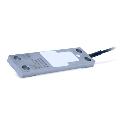
HBM SLB700A/06VA1 User manual

A3253-2.0 en/de/fr
Strain transducer
Dehnungsaufnehmer
Extensomètre
SLB700A/06VA1
SLB700A/06VA2
Montageanleitung
Mounting Instructions
Notice de montage

English Page 3 - 18.................................................
Deutsch Seite 19 - 34...............................................
Français Page 35 - 50...............................................

3
SLB700A/06VA1, SLB700A/06VA2
A3253-2.0 en/de/fr HBM
Contents Page
English
Safety instructions 4..............................................
1 Scope of delivery 8............................................
2 General application instructions 8..............................
3 Structure and mode of operation 9..............................
3.1 Transducer 9.............................................
3.2 Strain gage and integrated electronics cover protection 9.......
4 Conditions on site 10...........................................
4.1 Ambient temperature 10.....................................
4.2 Moisture and chemical effects 10.............................
4.3 Deposits 11................................................
5 Mechanical installation 12.......................................
5.1 Important precautions during installation 12....................
5.2 General installation guidelines 12.............................
5.3 Installation of the SLB 700A/06VA1 and SLB 700A/06VA2 12.....
6 Electrical connection 14.........................................
6.1 Pin assignment 14..........................................
6.2 Shortening the cable 14.....................................
6.3 Cable extension 14.........................................
6.4 Calibration 15..............................................
6.5 Zero setting 16.............................................
7 Specifications 17...............................................
8 Dimensions 18.................................................

SLB700A/06VA1, SLB700A/06VA2
4
A3253-2.0 en/de/frHBM
Safety instructions
Proper use
The SLB700A/06VA1 and SLB700A/06VA2 strain transducers are solely de-
signed for measuring static and dynamic strains within the load limits specified
by the technical data for the respective maximum capacities. Any other use is
not the designated use. The strain transducers work with force shunt mea-
surements. It is therefore necessary to screw the strain transducer to the
structure, on which strain is to be measured, in compliance with the specifica-
tions in these mounting instructions. The SLB700VA1 and SLB700VA2 strain
transducers are not suitable for force flow measurements.
To ensure safe operation, the regulations in the mounting and operating in-
structions, together with the following safety rules and regulations, and the
data specified in the technical data sheets, must be complied with. It is also
essential to observe the applicable legal and safety regulations for the ap-
plication concerned, e.g. accident prevention regulations.
The strain transducers are not intended for use as safety components. Please
also refer to the section: ”Additional safety precautions”. Proper and safe op-
eration of the strain transducer requires proper transportation, correct storage,
siting and mounting, and careful operation.
Load limits
The data in the technical data sheet must be complied with when using the
strain transducer. In particular, the respective maximum loads specified must
never be exceeded. The following limits set out in the technical data sheets
must not be exceeded
Limit strains,
Breaking strains,
Permissible dynamic strains,
Temperature limits,
Limits of electrical loading capacity.
Please note that when several strain transducers are interconnected, the
strain distribution is not always uniform.
Use as a machine element
The strain transducers can be used as machine elements. When used in this
manner, it must be noted that, to favor greater sensitivity, the strain transduc-
ers are not designed with the safety factors usual in mechanical engineering.
Please refer here to the section ”Loading limits” and the technical data.

5
SLB700A/06VA1, SLB700A/06VA2
A3253-2.0 en/de/fr HBM
Additional safety precautions
The strain transducers cannot (as passive transducers) implement any (safe-
ty-relevant) cutoffs. This requires additional components and constructive
measures for which the installer and operator of the plant is responsible.
In cases where a breakage or malfunction of the transducer would cause in-
jury to persons or damage to equipment, the user must take appropriate addi-
tional safety measures that meet at least the requirements of applicable safety
and accident prevention regulations (e.g. automatic emergency shutdown,
overload protection, catch straps or chains, or other fall protection).
The layout of the electronics conditioning the measurement signal should be
such that measurement signal failure does not cause damage.
General dangers of failing to follow the safety instructions
The strain transducers are state-of-the-art and reliable. T ransducers can
give rise to residual dangers if they are incorrectly operated or inappropriately
mounted, installed and operated by untrained personnel. Every person in-
volved with siting, starting-up, operating or repairing a strain transducer must
have read and understood the mounting instructions and in particular the
technical safety instructions. The strain transducers can be damaged or de-
stroyed by non-designated use of the strain transducer or by non-compliance
with the mounting and operating instructions, these safety instructions or any
other applicable safety regulations (BG safety and accident prevention regula-
tions) when using the strain transducers. The strain transducers can break
apart, especially when overloaded. A strain transducer breakage could injure
persons in the vicinity of the strain transducer or cause damage to equipment.
If strain transducers are not used according to their designated use, or if the
safety instructions or specifications in the mounting and operating instructions
are ignored, it is also possible that the strain transducer may fail or malfunc-
tion, with the result that persons or property may be affected (due to the loads
acting on or being monitored by the strain transducer).
The scope of supply and performance of the transducer covers only a small
area of measurement technology, as measurements with (resistive) strain
gage sensors presuppose the use of electronic signal processing. In addition,
equipment planners, installers and operators should plan, implement and re-
spond to safety engineering considerations in such a way as to minimize re-
maining dangers.
The markings used in this document
The marking below warns of a potentially dangerous situation in which failure
to comply with safety requirements can result in death or serious physical in-
jury.

SLB700A/06VA1, SLB700A/06VA2
6
A3253-2.0 en/de/frHBM
WARNING
Description of a potentially dangerous situation
Measures to avoid/prevent the danger
The marking below warns of a situation in which failure to comply with safety
requirements could lead to damage to property.
NOTE
Description of a situation that could lead to damage to property
The marking below draws your attention to important information about the
product or about handling the product.
Important
Important information
The marking below contains application tips or other information that is useful
to you.
Tip
Information/Application instructions
Conversions and modifications
The transducer must not be modified from the design or safety engineering
point of view except with our express agreement. Any modification shall ex-
clude all liability on our part for any damage resulting therefrom.
Maintenance
The SLB‐700A/06VA1 and SLB‐700A/06VA2 strain transducers are mainte-
nance-free.

7
SLB700A/06VA1, SLB700A/06VA2
A3253-2.0 en/de/fr HBM
Disposal
In accordance with national and local environmental protection and material
recovery and recycling regulations, old transducers that can no longer be
used must be disposed of separately and not with normal household waste.
If you need more information about waste disposal, please contact your local
authorities or the dealer from whom you purchased the product.
Qualified personnel
Qualified personnel means persons entrusted with siting, mounting, starting
up and operating the product, who possess the appropriate qualifications for
their function.
This includes people who meet at least one of the three following require-
ments:
- Knowledge of the safety concepts of measurement and automation
technology is a requirement and as project personnel, you must be familiar
with these concepts.
- As measurement and automation plant operating personnel, you have been
instructed how to handle the machinery. You are familiar with the operation
of the equipment and technologies described in this documentation.
- As commissioning engineers or service engineers, you have successfully
completed the training to qualify you to repair the measurement and au-
tomation systems. You are also authorized to activate, ground and label cir-
cuits and equipment in accordance with safety engineering standards.
It is also essential to comply with the legal and safety requirements for the ap-
plication concerned during use. The same applies to the use of accessories.
The strain transducers must only be installed by qualified personnel, strictly in
accordance with the specifications and with the safety requirements and regu-
lations listed below.

SLB700A/06VA1, SLB700A/06VA2
8
A3253-2.0 en/de/frHBM
1 Scope of delivery
1 strain transducer SLB‐700A/06VA1 (version with voltage output 0 to 10V)
or SLB‐700A/06VA2 (version with current output 4 to 20mA)
1 Mounting instructions
2 General application instructions
The SLB‐700A/06VA1 and SLB‐700A/06VA2 strain transducers are suitable
for the measurement of positive and negative strains. They provide highly ac-
curate static and dynamic force measurements and must therefore be han-
dled very carefully. Particular care must be taken when transporting and
installing the devices. Dropping or knocking the transducers may cause per-
manent damage.
The specifications list the permissible limits for mechanical, thermal and elec-
trical stress. It is essential that these are taken into account when planning the
measuring set-up, during installation and, ultimately , during operation.

9
SLB700A/06VA1, SLB700A/06VA2
A3253-2.0 en/de/fr HBM
3 Structure and mode of operation
3.1 Transducer
A solid connection is formed between the strain transducer and the measure-
ment object with the four screws. Mechanical loading causes a change in
length of the measurement object which is then transferred to the strain trans-
ducer. The change in length changes the electrical resistance of the installed
strain gage proportional to the strain. This is converted into the output signal
by the integrated DC amplifier. The SLB‐700A/06VA1 outputs a voltage be-
tween 0 and 10V, the SLB‐700A/06VA2 a current between 4 and 20mA.
3.2 Strain gage and integrated electronics cover protection
The strain transducer is potted with a special silicone mass at appropriate
points to protect the strain gages and the integrated amplifier electronics. This
securely protects the sensitive components against environmental influences.
The silicone must not be damaged or removed.
Strain link
XXXXXXX
Un=19...30V
1Wmax
#xxxxxxxxx
Top
Bottom
Silicone cover
Fig. 3.1: Silicone cover

SLB700A/06VA1, SLB700A/06VA2
10
A3253-2.0 en/de/frHBM
4 Conditions on site
4.1 Ambient temperature
Temperature changes lead to an expansion of the structure and therefore to a
change in the zero point. The strain transducers are therefore compensated
so that they can equalize and not display the thermal strain of the structure.
This compensation is implemented for standard construction and tool steels ,
e.g. C45, 1.1730, with a thermal expansion coefficient of 12 10‐6/C.
If mounted on a structure with a different thermal expansion coefficient, a tem-
perature-dependent signal is output that corresponds to the temperature ex-
pansion of the material less 12 10‐6/C.
Tip
If it is possible to reset (zero setting) the zero signal at short intervals, the in-
fluence of the temperature change on the zero signal can be ignored.
The influence of the temperature on the sensitivity is low. The influence re-
sults mainly from the change in the E modulus of the object on which the
strain transducer is mounted. The E modulus becomes smaller under the in-
fluence of heat and therefore a greater strain and higher measured value will
result when the same force is applied to the component. The reverse effect
occurs under the influence of cold.
To obtain optimum measurement results, the nominal (rated) temperature
range must be complied with.
4.2 Moisture and chemical effects
The transducers reach the protection class IP65 as per DIN EN 60529 (test
conditions: 0.5 hours under 1m water column) and are therefore briefly wa-
tertight. Nevertheless, the transducers must be protected against long-term
effects of moisture or weather such as rain, snow, etc.
The transducers must be protected against chemicals that could attack the
transducer body steel, silicone or the cable.
With stainless steel transducers, please note that acids and all materials
which release ions will also attack stainless steels and their welded seams.
Should there be any corrosion, this could cause the transducer to fail. In this
case, appropriate protective measures should be implemented.

11
SLB700A/06VA1, SLB700A/06VA2
A3253-2.0 en/de/fr HBM
4.3 Deposits
Dust, dirt and other foreign matter must not be allowed to accumulate suffi-
ciently to divert some of the measuring force onto the housing, thus invalidat-
ing the measured value (force shunt). Foreign matter should not be allowed to
collect on top of or underneath the strain transducer.

SLB700A/06VA1, SLB700A/06VA2
12
A3253-2.0 en/de/frHBM
5 Mechanical installation
5.1 Important precautions during installation
Handle the transducer with care.
Make sure that the transducer cannot be overloaded.
WARNING
There is a danger of the transducer breaking if it is overloaded. This can
cause danger for the operating personnel of the system in which the
transducer is installed.
Implement appropriate safety measures to avoid overloads or to protect
against resulting dangers.
5.2 General installation guidelines
The strain/compression of the structure (measurement object) to be recorded
by the transducer is transferred to the transducer via the two screwed on
mounting surfaces. Therefore a perfectly flat, distortion-free contact surface is
decisive for reproducible measurement results. To measure the strain of
500m/m, the contact surface must be able to generate a force of approx.
3000N in the measuring body.
5.3 Installation of the SLB 700A/06VA1 and SLB 700A/06VA2
The strain transducer SLB700A is screwed onto the measurement object with
four standard M6 hexagon socket screws (e.g. DIN 912). We recommend, for
the best measurement results, screws with property class 12.9, that can be
tightened with a tightening torque of 16 Nm in a diagonally opposed se-
quence.
Remove any coatings, paint or paint residues from the mounting area for
the transducer.
The surface of the measurement object must be sufficiently flat (roughness
Ra 3.2).
The strain transducer must not touch in the central lower area (see
Fig. 5.1) and must be mounted without tension.
Mount the strain transducer as shown in Fig. 5.1.

13
SLB700A/06VA1, SLB700A/06VA2
A3253-2.0 en/de/fr HBM
Cover the transducer with a housing if there is a risk of exposure to
weather or danger of mechanical damage. Also protect against
condensation.
Measurement
object
Fig. 5.1: Installation of the strain transducer
Load the transducer before calibration several times with the maximum load
so that the mounting area can settle. Then tighten the fixing screws with the
nominal torque.

SLB700A/06VA1, SLB700A/06VA2
14
A3253-2.0 en/de/frHBM
6 Electrical connection
The strain transducers are equipped with a 6 m long, six-wire connection
cable. The transducers must be calibrated after being mounted in the applica-
tion. The output signal characteristic curve is factory preset to approx.
330m/m for a signal spread of 1 to 9V or from 5.5 to 18.5mA.
6.1 Pin assignment
Connection Wire color SLB‐700A/06VA1 SLB‐700A/06VA2
Supply voltage blue 19 30V 19 30V
Supply voltage black 0V 0V
Output signal white 0 10V 4 20mA
Output signal 0V gray 0V No function
Control input IN1 (zero setting) red
Control input IN2 (calibration) green
Cable shield connected to housing
Important
In the SLB‐700A/06VA1, the supply voltage 0V (black) and output signal 0V
(gray) are connected internally.
Tip
The inputs/outputs of the SLB‐700A/06VA1 and SLB‐700A/06VA2 are pro-
tected against short circuits and reverse polarity.
6.2 Shortening the cable
The cable can be shortened without restrictions.
6.3 Cable extension
Only use shielded, low-capacitance measurement cables for extension. En-
sure that connection is perfect, with a low contact resistance. Please note that
the total cable length should not exceed 30 m.

15
SLB700A/06VA1, SLB700A/06VA2
A3253-2.0 en/de/fr HBM
6.4 Calibration
During calibration, a specific strain is initially assigned the output signal of 1V
or 5.5mA. This is the ”lower range value” or zero point of the characteristic
curve. You can assign the output signal of 9V or 18.5mA to any other strain.
This is the ”upper range value” or end point of the characteristic curve. This
procedure is also possible if you are working with negative strains, i.e. with
the appropriate adjustment compressions (negative strains) will lead to posi-
tive voltage or current changes at the output.
Settlement, running in and overshooting or temperature drift can lead to sig-
nals below or above the calibrated zero or full scale. The electronics are
therefore set so that 10% of the measurement range is still available above
and below the calibrated range.
To use the digital calibration function of the transducer, the control input IN2
must be controlled with appropriate switching levels. You can either use a
pushbutton or the digital outputs of a programmable control unit. The switch-
ing level for inactive lies between 0 and 4V, for active between 10 and 30V.
Important
Please note the mechanical limit values in the specifications during calibra-
tion, particularly the maximum operating strain of 750mm/m. Please also note
that very small strain differences between the start and end point (under
50mm/m) will lead to a very high amplification and therefore to an ”unsteady”
signal.
Procedure
1. Set up the starting condition for your measurement object.
2. Apply the switching level for active for minimum 2 seconds at the control
input IN2 (10 30V).
The characteristic curve is reset to the factory setting and the signal for the
zero point of 1 V or 5.5 mA is output.
3. Raise the strain for the planned end value.
4. Apply the switching level for active for maximum 1 second at the control in-
put IN2 (10 30V).
The new characteristic curve is calculated and permanently stored in the
device. The signal for the end point of 9V or 18.5mA is output.

SLB700A/06VA1, SLB700A/06VA2
16
A3253-2.0 en/de/frHBM
6.5 Zero setting
Apply the switching level for active at the control input IN1 (10 30V) for
zero setting. The output signal is then set to the start point of the characteris-
tic curve (1V or 5.5mA) for the strain currently present.
Important
The determined zero value is not permanently stored. This means that the
zero value determined during zero setting is deleted when the operating volt-
age is switched off. Zero and end point of the calibration are however perma-
nently stored.

17
SLB700A/06VA1, SLB700A/06VA2
A3253-2.0 en/de/fr HBM
7 Specifications
Type SLB‐700A/06VA1 SLB‐700A/06VA2
Nominal (rated) measuring range m/m 0 500 0 500
Minimum operating range m/m 0 50 0 50
Zero signal (signal at zero point) 1V 5.5mA
End signal (signal for end point) 9V 18.5mA
Output signal spread 8V 13mA
Output signal range -0.3 11V 3 21mA
Relative linearity error % 0.5
Cut-off frequency (‐1dB) Hz 1000
Matched to material with a thermal expansion
coefficient of 1/C12 10‐6
Level control inputs IN1/IN2 Vactive (high): 10V; inactive (low): 4V
Reference excitation voltage V 24
Nominal (rated) range of the excitation voltage V DC 19 30
Max. current consumption mA 20
Nominal temperature range C-10 50
Operating temperature range C-20 60
Storage temperature range C-40 85
Maximum operating strain m/m 750
Breaking strain m/m 1500
Restoring force Napprox. 3200
Vibration
as per DIN EN60068‐2‐6
Hz 10 500
Maximum shock loading
as per DIN EN60068‐2‐27
g 50
Degree of protection
as per DIN EN60529
IP65
Tightening torque of mounting screws
minimum
Nominal (rated) value
Nm
Nm
8
16
Cable sheath PUR
Cable length m 6
Cable diameter mm 3.5

SLB700A/06VA1, SLB700A/06VA2
18
A3253-2.0 en/de/frHBM
8 Dimensions
6,6
14,3
76,2
6070
25,4
89
10
Dimensions in mm

19
SLB700A/06VA1, SLB700A/06VA2
A3253-2.0 en/de/fr HBM
Inhalt Seite
Deutsch
Sicherheitshinweise 20.............................................
1 Lieferumfang 24................................................
2 Allgemeine Anwendungshinweise 24.............................
3 Aufbau und Wirkungsweise 25...................................
3.1 Aufnehmer 25..............................................
3.2 Abdeckung der DMS und der integrierten Elektronik 25..........
4 Bedingungen am Einbauort 26...................................
4.1 Umgebungstemperatur 26...................................
4.2 Feuchtigkeit und chemische Einwirkung 26....................
4.3 Ablagerungen 27...........................................
5 Mechanischer Einbau 28........................................
5.1 Wichtige Vorkehrungen beim Einbau 28.......................
5.2 Allgemeine Einbaurichtlinien 28..............................
5.3 Einbau des SLB‐700A/06VA1 und SLB‐700A/06VA2 28.........
6 Elektrischer Anschluss 30.......................................
6.1 Anschlussbelegung 30......................................
6.2 Kabelkürzung 30...........................................
6.3 Kabelverlängerung 30.......................................
6.4 Kalibrierung 31.............................................
6.5 Nullsetzen 32..............................................
7 Technische Daten 33............................................
8 Abmessungen 34...............................................

SLB700A/06VA1, SLB700A/06VA2
20
A3253-2.0 en/de/frHBM
Sicherheitshinweise
Bestimmungsgemäße Verwendung
Die Dehnungsaufnehmer SLB700A/06VA1 und SLB700A/06VA2 sind aus-
schließlich für die Messung statischer und dynamischer Dehnungen im
Rahmen der durch die technischen Daten spezifizierten Belastungsgrenzen
konzipiert. Jeder darüber hinausgehende Gebrauch ist nicht bestimmungs-
gemäß. Die Dehnungsaufnehmer arbeiten durch Messung im Kraftneben-
schluss. Hierzu ist es notwendig, die Dehnungsaufnehmer nach den
Vorgaben dieser Montageanleitung an die Konstruktion zu schrauben, an der
die Dehnungen gemessen werden sollen. Die Dehnungsaufnehmer
SLB700VA1 und SLB700VA2 sind nicht geeignet zur Messung im Kraftfluss.
Zur Gewährleistung eines sicheren Betriebes sind die Vorschriften der
Montage‐ und Betriebsanleitung sowie die nachfolgenden Sicherheitsbestim
mungen und die in den technischen Datenblättern angegebenen Daten unbe-
dingt zu beachten. Zusätzlich sind die für den jeweiligen Anwendungsfall zu
beachtenden Rechts‐ und Sicherheitsvorschriften zu beachten, z.B. die
Unfallverhütungsvorschriften der Berufsgenossenschaften.
Die Dehnungsaufnehmer sind nicht zum Einsatz als Sicherheitsbauteile
bestimmt. Bitte beachten Sie hierzu den Abschnitt „Zusätzliche Sicherheits-
vorkehrungen“. Der einwandfreie und sichere Betrieb der Kraftaufnehmer
setzt sachgemäßen Transport, fachgerechte Lagerung, Aufstellung und
Montage sowie sorgfältige Bedienung voraus.
Belastungsgrenzen
Beim Einsatz der Dehnungsaufnehmer sind die Angaben in den technischen
Datenblättern unbedingt zu beachten. Insbesondere dürfen die jeweils
angegebenen Maximalbelastungen keinesfalls überschritten werden. Nicht
überschritten werden dürfen die in den technischen Datenblättern angege-
benen
Grenzdehnungen,
Bruchdehnungen,
Zulässige dynamische Dehnungen,
Temperaturgrenzen,
Grenzen der elektrischen Belastbarkeit.
Beachten Sie bei der Zusammenschaltung mehrerer Dehnungsaufnehmer,
dass die Dehnungsverteilung nicht immer gleichmäßig ist.
Einsatz als Maschinenelemente
Die Dehnungsaufnehmer können als Maschinenelemente eingesetzt werden.
Bei dieser Verwendung ist zu beachten, dass die Dehnungsaufnehmer zu
This manual suits for next models
1
Table of contents
Languages:
Other HBM Transducer manuals
Popular Transducer manuals by other brands

Humminbird
Humminbird PIRANHAMAX 4 install guide

Thinkrace
Thinkrace VT460 user manual

Spectris
Spectris HBM U2B Mounting instructions

Gems Sensors & Controls
Gems Sensors & Controls 4000K Series Operating & installation instructions

Gems
Gems 2200 Series Operating & installation instructions

Emerson
Emerson Rosemount 3051 Reference manual