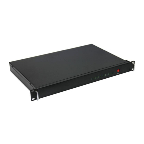
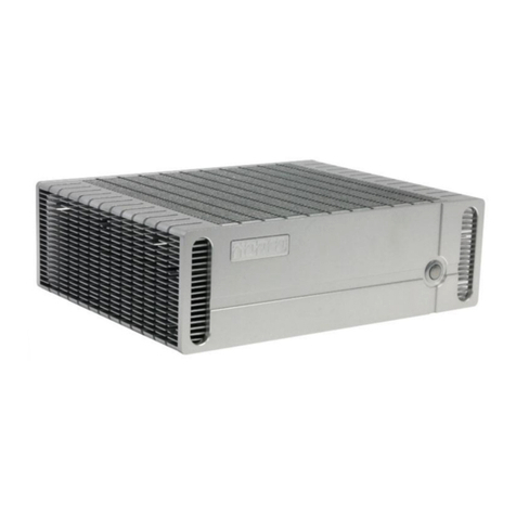
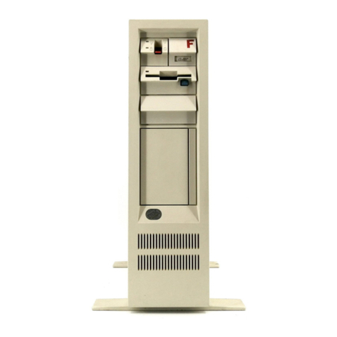
Norco BIS-6620 User manual

BIS-6620
Mini PC
USER' Manual V1.0

BIS-6620
Mini PC
USER' Manual V1.0
Shenzhen NORCO Intelligent Technology Co., Ltd.:0755-27331166
Beijing:010-82671166
Shanghai:021-61212088
Nanjing: 025-58015489
Chengdu:028-85259319
Shenyang:024-23960846
Xi’an:029-88338386
Nanjing: 025-58015489
Wuhan:027-87858983
Tianjin:022-23727100
Singapore:65-68530809
Netherlands:31-040-2668554
Web:www.norco.cn

Shenzhen NORCO Intelligent Technology Co.,Ltd.
BIS-6620 Mini PC
Place/Data: HONG KONG/2009

Trade Name:Shenzhen NORCO Intelligent Technology Co.,Ltd.
Model Name:BIS-6620
Responsible Party:Shenzhen NORCO Intelligent Technology Co.,Ltd.
Equipment Classification:FCC Class B Subassembly
Type of Product:BIS-6620 Mini PC
Manufacturer:Shenzhen NORCO Intelligent Technology Co.,Ltd.
Date: 2009

Copyright
With the exception of showing the accessories of product configuration, this
manual does not create any commitment of our company. We retained the rights to
change it without prior notice. We will not be responsible for any installation, the
result of improper use of direct, indirect, intentional or unintentional damage or
hidden dangers.
Before buying products, please learn about product performance from the seller
to see if it is in line with your needs. NORCO is a registered trademark of Shenzhen
NORCO Intelligent Technology CO., Ltd. Other trademarks involved in this manual,
their ownership are owned by its respective owners. The contents of this manual are
protected by copyright law. All rights are strictly reserved. Any form of unauthorized
reproduction including but not limited to carbon copy, facsimile transmission and
electronic copy or email should be destroyed immediately.

Safety Instructions
1. Please read the safety instructions carefully.
2. Before inserting or removing expansion cards, re-assembling or re-configuring,
disconnect the computer and peripherals from their power sources to prevent
electric shock or system board damage.
3. Before attempting to move the product, the system must be powered-down and
the power cord must be disconnected from the power source.
4. Before connecting or disconnecting any signal line, first turn off all power
resources and disconnect the power cord from power source.
5. To help avoid possible damage to system boards, wait at least 30 seconds after
turning off the computer before re-turning on the computer.
6. Use cross head screwdriver to operate. A magnetic screwdriver is recommended
(magnet to collect screws).Do not leave any tools or components inside the chassis.
7. Assure abundant cooling and streamline ventilation.
8. If anything unexpected exists during Equipment used, please contact the
professionals.

Contents
Chapter 1 Product Introduction .................................................................................1
1.1 Brief Introduction.................................................................................................1
1.2 Features.............................................................................................................. 1
1.3 Hardware Specification .......................................................................................2
1.4 Product Dimension.............................................................................................. 7
Chapter 2 Hardware Functions ................................................................................. 5
2.1 External Interface Direction.................................................................................5
2.2 Jumper Setting.................................................................................................... 5
2.2.1 CMOS Content Clearing and Saving Settings(JCC) ................................... 6
2.2.2 COM2 Jumper Function Setting(J1、J2、J3) ............................................. 7
2.3 Interface Instruction ............................................................................................ 8
2.3.1 CF Card Slot(CF) ........................................................................................ 8
2.3.2 SD Reader Slot(SD)....................................................................................8
2.3.3 USB Port(USB1,USB2,USB3)................................................................8
2.3.4 Audio(SPK OUT,MIC)............................................................................... 9

2.3.5 Ethernet Port(LAN)......................................................................................9
2.3.6 Keyboard & Mouse Interface(Ms/Kb) ........................................................ 10
2.3.7Power Interface(DC 12V) ........................................................................... 11
2.3.8 SATA Port(SATA) ..................................................................................... 12
2.4 BIS-6620I Expansion board interface ............................................................... 12
2.4.1 VGA port(VGA) ......................................................................................... 12
2.4.2 SVIDEO Port(SVIDEO) ............................................................................. 13
2.5 BIS-6620IIExpansion board interface ............................................................... 14
2.5.1 DVI interface(DVI) ..................................................................................... 14
2.5.2 Serial Port(COM)....................................................................................... 15
Chapter 3 Hardware installation..............................................................................13
3.1 Remove machine upper cover ..........................................................................13
3.2 Memory Module Replacement/Installation ........................................................ 13
3.3 Hard drive replacement/installation................................................................... 14
3.4 Wall mounting/Displayer installtion.................................................................. 15
3.5 Power Connection ........................................................................................... 16

Chapter 4 BIOS Setup ............................................................................................ 17
4.1 Main Menu ........................................................................................................ 18
4.2 Advanced.......................................................................................................... 19
4.2.1 CPU Configuration ......................................................................................... 20
4.2.2 IDE Configuration........................................................................................... 22
4.2.3 Hardware Health Configuration...................................................................... 23
4.2.4 ACPI Configuration ........................................................................................ 24
4.2.5 MPS Configuration......................................................................................... 27
4.2.6 PCI Express Configuration............................................................................. 28
4.2.7 Smbios Configuration..................................................................................... 29
4.2.8 USB Configuration ......................................................................................... 30
4.3 PCI PnP ............................................................................................................ 34
4.4 Boot .................................................................................................................. 36
4.5 Security............................................................................................................. 38
4.6 Chipset.............................................................................................................. 41
4.6.1 North Bridge Configuration ............................................................................ 41
4.6.2 South Bridge Configuration............................................................................ 43
4.7 Exit.................................................................................................................... 45
Appendix................................................................................................................. 45
Appendix 1: Driver Installation ................................................................................ 45
Appendix 2: Embed SATA HDD Drivers into Windows XP Installation Disc ........... 47
Appendix 3: Watchdog Programing Instruction....................................................... 50
Appendix 4: Glossary.............................................................................................. 53

Packing List
Thank you very much for choosing our products. Please check your package
completely as the following item checklist first, if you find any components lost or
damaged, please contact your retailer.
■ BIS-6620 1pcs
1pcs
1pcs
1pcs
1set
1pcs
1bag
■User’s Manual
■Drive Disk
■Power Cord
■Power Adapter
■1 to 4 serial port(optional)
■Screw

Chapter 1
Product Introduction

BIS-6620 Fanless Embedded Mini Box PC
Chapter 1 Product Introduction
1.1 Brief Introduction
BIS-6620 is a compact thin client pc based on Intel Menlow platform which
combines prowerful logical abilities with low power consumption of 5.5W. The
various storage modes including SATA, SD and CF card and diverse display
terminals provide customers with more choices. Besides, the customized expansion
slots make it’s an easy-to-expand product.
BIS-6620 can be effectively applied to digital signage system, high-definition
media player, advertising machine, LCD large screen controller, set-top boxes,
medical instruments, finance, education and other terminal markets and industrial
solutions.
1.2 Features
● Mini-size, ultra-low noise, fanless radiating system
BIS-6620 is designed with fanless radiating system which makes it possible to
reduce the noise to 30db when it operates. It is fixed in 120mm×120mm×40mm---
tiny and compact enough to operate in tight space.
1

BIS-6620 Fanless Embedded Mini Box PC
● Onboard Intel Atom processor
The onboard Intel Atom Z5XX processor with a lower-power-consumption of
2.5W and high-performance can be effectively combined with the Poulsbo SCH
chipset to form an excellent solution for embedded platform.
● Multiple Interfaces
BIS-6620 I/O ports include:Line-out ,Mic-out,USB2.0 port,RJ-45 network
ports。BIS-6620 also provide VGA+S-Video or DVI+4COM output (VGA & DVI is
optional)
●Convenient Installation
BIS-6620 meets VESA MOUNT MIS-D standard which makes it convenient to
be installed on the back of liquid crystal equipment or placed on the desk.
1.3 Hardware Specification
System
Model BIS-6620I BIS-6620II BIS-6620III BIS-6620IV
Motherboard
BPC-7652+AFC-4
40V
BPC-7652+AFC
-340
BPC-7652+
AFC-341V
BPC-7652+
AFC-450H
2

BIS-6620 Fanless Embedded Mini Box PC
Processor Intel Atom Z510(1.1GHz FSB400MHz)/Z530(1.6GHz FSB400MHz)
Chipset Intel poulsbo SCH
Interface
VGA+
S-VID
EO
DVI
VGA HDMI
Controlle
r
Intel Poulsbo Integrated GMA500
Display
Memory Dynamic sharing 256MB as video memory
System
Memory
Onboard 1x200Pin SO-DIMM supports DDRII up to 2GB
Remark:SO-DIMM can support 2 Rank,the capacity is 512Mb,1Gb
&2Gb,suggest use RAM of x16 memory chips
SSD 1x CF slot supports Type II CompactFlash,1x SD socket
Storage
HDD
1x1.8” HDD tray supports Ultra DMA 100/66/33&SATA II
HDD
Chip Winbond W83627DHG I/O
PS/2 1x MS/KB
3

BIS-6620 Fanless Embedded Mini Box PC
COM -- 4xCOM 4xCOM --
USB
4x
USB2
.0 (2
on
front
panel
)
2x USB2.0 (front
panel)
4x USB2.0(2
on front panel)
5x USB2.0(2
on front panel)
Audio 1x Mic-in, 1x Line-out
LPT ---
Ethernet Realtek RTL8111C, 10/100/1000Mbps, 1x RJ45
WIFI USB mode
Extension
interface
--
System
Control
Switch Button
4

BIS-6620 Fanless Embedded Mini Box PC
LED Indicator Power supply , hard disk LED
Power supply DC +12V
Cooling
System
Fanless
OS Windows Vista/XP/CE/XPE,Linux
Mechanical &
Environmenta
l
Operating
Temperature
0℃~60℃
Storage
Temperature
-40℃~85℃
Relative
Humidity
5%~95%, 40℃, no-condensation
Vibration 0.5g rms/5~500Hz/ random assignment
EMC CE/FCC Class B
5

BIS-6620 Fanless Embedded Mini Box PC
Product
Dimension
120mm×120mm×40mm (W×D×H)
Package
Dimension
275mm×255mm×115mm (W×D×H)
Net Weight 0.7KG
Gross Weight 1.5KG
Material High-tensile steel
Surface
Treatment
Sand blast and oxidation
Installation Wall-mount or Desktop
Color Silver gray/Black
6

BIS-6620 Fanless Embedded Mini Box PC
1.4 Product Dimension
Dimension:120mmx120mmx40mm(WxDxH)
7

Chapter 2
Hardware Functions
Other manuals for BIS-6620
1
Table of contents
Other Norco Desktop manuals

Norco
Norco BIS-6622 II User manual

Norco
Norco BIS-6680H User manual

Norco
Norco EMB-7535 User manual

Norco
Norco BIS-1280 User manual

Norco
Norco BIS-1280A40 User manual

Norco
Norco BIS-6660C User manual

Norco
Norco BIS-6540HD User manual

Norco
Norco EMB-7570 User manual

Norco
Norco EMB-3531 User manual

Norco
Norco BIS-6620 User manual