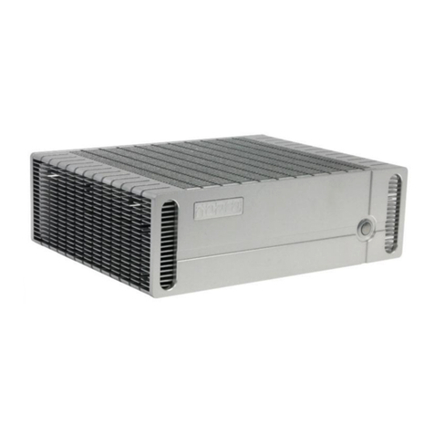
Norco BIS-6622 II User manual

BIS-6622
Mini PC
USER' Manual V1.0

Announcement
With the exception of showing the accessories of product configuration, this manual
do not create any commitment of our company. We retained the rights to change it
without prior notice and will not be responsible for any direct, indirect, intentional or
unintentional damage or hidden dangers caused by any improper installation or use.
Before ordering products, please learn about the product performance from the
distributors to see if it is in line with your needs. NORCO is a registered trademark of
Shenzhen NORCO Intelligent Technology CO.,LTD.The ownership of other
trademarks involved in this manual is owned by its respective owners. The contents
of this manual are protected by copyright law. All rights are strictly reserved. Any
form of unauthorized reproduction including but not limited to carbon copy, facsimile
transmission and electronic copy or email is prohibited.

Safety Instructions
1. Before using this product, please read this user’s manual carefully;
2. Before moving the host, please make sure to unplug the AC
power cords out of the sockets;
3. Before you connect or unplug any equipment, please make sure that all
power cords are unplugged in advance;
4. To prevent any unnecessary damage to the products due to frequent power on/off.
Please wait at least 30 seconds to restart the unit.
5. Please use cross screwdriver to operate the unit, a consolidated one for better.
( with magnetism, to avoid leaving screws inside the chassis). Never leave any tools
or parts inside chassis.
6. Before cleaning the host, please disconnect the power supply first.
Pleaes use wet cloth to clean, don’t use liquid or spray cleanser.
7. When the host is operating, please make sure that no liquid poured into
it,which may cause fire or damage.
8. If any exceptions occurred during the operating, please look for help from
professionals.

Content
Chapter 1. Product Introduction ................................................................................................. 1
1.1 Overview .........................................................................................错误!未定义书签。
1.2 Features ........................................................................................................................ 1
1.3 Specification.................................................................................................................. 1
1.4 Product Dimension Diagram ......................................................................................... 3
Chapter 2. Hardware Features................................................................................................... 4
2.1 External Interface Index Map ........................................................................................ 4
2.2Jumper Setting............................................................................................................... 5
2.2.1 LVDS Voltage Jumper Setting(J2).................................................................. 5
2.3 Interface Specification................................................................................................... 5
2.3.1 USB Ports(USB1, USB2, USB3).................................................................... 5
2.3.2 Audio Interface(SPKOUT, MIC)...................................................................... 6
2.3.3 Ethernet Port(LAN)........................................................................................ 6
2.3.4 COM and CAN(COM1,J1)........................................................................... 6
2.3.5 LVDS Connector ............................................................................................... 7
2.3.6 LVDS Backlight Control(J1)............................................................................ 7
2.3.7 Expansion(MINIPCIE).................................................................................... 8
3.2.8 Power Interface(DC 12V)............................................................................... 8
2.4 BIS-6622 Expansion Board(AFC-442V,AFC-450H)Interface ................................ 8
2.4.1 SATA Interface(SATA).................................................................................... 8
2.4.2 VGA Interface(VGA)....................................................................................... 8
2.4.3 HDMI Interface(HDMI)................................................................................... 9
2.4.4 USB Interface(USB1, USB2, USB3).............................................................. 9
Chapter 3. Hardware Installation.............................................................................................. 10
3.1 Dismount Host Cover.................................................................................................. 10
3.2 HDD Replacement/Installation.................................................................................... 10
3.3 Power Connection....................................................................................................... 10
Chapter 4. BIOS Setup..............................................................................................................11
4.1 Main Menu .................................................................................................................. 12
4.2 Advanced Menu .......................................................................................................... 13

4.2.1 ACPI Configuration ........................................................................................... 14
4.2.2 CPU Configuration ............................................................................................ 15
4.2.3 Wake On Lan Configuration.............................................................................. 16
4.2.4 USB Configuration ............................................................................................ 17
4.3 Chipset Menu.............................................................................................................. 18
4.3.1 North Bridge...................................................................................................... 19
4.3.2 South Bridge ..................................................................................................... 20
4.4 Boot Menu................................................................................................................... 21
4.5 Security Menu ............................................................................................................. 22
4.6 Save&Exit Menu ......................................................................................................... 23
Appendix .................................................................................................................................. 23
Appendix 1: Glossary........................................................................................................ 23

Chapter 1. Product
Introduction

BIS-6622 Mini PC Based on Intel Atom E6XX Processor
1
Chapter 1 Product Introduction
1.1 Overview
BIS-6622II is a type of embedded barebone system developed around Intel® Atom™ E6xx
0.6G, 1G, 1.3G, 1.6GHz processor. This platform is featured by its ultra low power consumption
and excellent 2D/3D image display performance, supporting hardware decode of MPEG4,
H.263, H.264 and hardware acceleration of MPEG2, MPEG4, VC1, WMV9, H.264.
BIS-6622II supports 1x 1.8” SATA HDD , 5×USB 2.0 and onboard 1 GB DDR2 800 MHz RAM.
The board supports 2×Gigabit Ethernet as well as the WiFi functions with an optional external
WiFi antenna connector. With 12V DC power input, this embedded board can work effectively
under a wide range temperature( -10°C ~ 50°C)
With the great performance, low power consumption and an ultra compact enclosure with the
dimension of only 122mm×122 mm×45 mm , BIS-6622II is the best solution for high graphic
display performance, low power consumption and space restricted applications. This board can
be used in a wide range of applications such as digital signage, in-vehicle infotainment,
multi-media devices, kiosk, surveillance and POS, ect.
1.2 Features
●Based on Intel Atom E6XX+EG20T chipset; featured by its high-performance &
low-power-consumption
●With super display performance, supporting HD video encoding and decoding
●VESA MOUNT ready for easy installation and mounting, supporting desktop and wall
mounting
●5×USB, 2×Gigabit Ethernet, 1× RJ 45, WiFi function supported
●Ultra compact fanless design with the dimension of only 122 mm×122 mm×45 mm
1.3 Specification
System
Model BIS-6622II BIS-6622IV

BIS-6622 Mini PC Based on Intel Atom E6XX Processor
2
Mainboard BPC-7672+AFC-442V BPC-7672+AFC-450H
Chipset Intel Atom E6XX+EG20T
Processor
Intel Atom E6XX(0.6G,1G,1.3GHz). Power consumption around
2.7W,3.3W,3.3W,3.9W
Memory Onboard 1G
Display
Display
Interface
1xVGA 1xHDMI
Controller Intel Atom E6XX Integrated
Videio
Memory
Dynamic shared 512M system memory as graphic memory
Storage
SSD Optional
HDD Inbuilt 1x1.8”HDD bay, supporting SATA II
I/0
PS/2 --
COM -- 4
Console 1xRJ45
USB 5x USB2.0( preposition 2*USB)
Audio 1x Mic-in, 1x line-OUT
Ethernet RTL8211CL+RTL8111D,10/100/1000Mbps, 2x RJ45
Expansion 1xMini PCIE, providing an external WIFI antenna interface
System Control Power On/Off button
LED Indicator Power, HDD LED indicator
Power Supply DC +12V
Cooling
System
Fanless
Operating
System
Windows 7/ Vista/xp/xpe/wince/Linux
Environment & Mechanical
Operating
Temperature
0℃~50℃
Storage
Temperature
-40℃~60℃

BIS-6622 Mini PC Based on Intel Atom E6XX Processor
3
Relative
Humidity
5%~95%,40℃, non-condensing
Anti-shock
Te s t
0.5g rms/5~500Hz/random operating
EMC CE/FCC Class B
Product
Dimension
121.5 mm×121.5 mm×44.5 mm (W×L×H)
Net Weight 500g
Material Aluminum Ally
Surface
Treatment
Sandblasting and Oxidation
Mounting Compliant with VESA MOUNT standard, Desktop and wall monuting supported.
Color Black
1.4 Product Dimension Diagram
Dimension: 120mmx120mmx40mm(LxWxH)

Chapter 2.
Hardware Features

BIS-6622 Mini PC Based on Intel Atom E6XX Processor
4
Chapter 2 Hardware Features
2.1 External Interface Index Map
1:BIS-6622 Front View:
2:BIS-6622II Rear View:
3:BIS-6622IV Rear View:

BIS-6622 Mini PC Based on Intel Atom E6XX Processor
5
2.2Jumper Setting
Please refer to the following jumper setting guide before installing your hareware devices
installation.
Remark: How to identify jumper and PIN1 of interface: Please observe the word mark of plug
socket, it will use “1”or bold line or triangular symbols; and please look at the back of
PCB,each interface weld spot has a squar point, which is PIN 1; and all the jumper PIN1 have a
white arrow on the side.
2.2.1 LVDS Voltage Jumper Setting(J2)
Before using the chosen LVDS, please make clear of its rated voltage, then choose the proper
voltage for this chosen LVDS via J2 jumper setting.
Pin Signal Name
2-4 3.3V
4-6 5V
2.3 Interface Specification
2.3.1 USB Ports(USB1, USB2, USB3)
Motherboard provides 2 standard USB interface ( USB 1and USB2 on the front panel) and one
4Pin USB(USB3).
USB1,2:
Pin Signal Name
1 VCC
2 USB_D-
3 USB_D+
4 GND
5 GND
6 GND
:

BIS-6622 Mini PC Based on Intel Atom E6XX Processor
6
Pin Signal Name
1 VCC
2 USB3-
3 USB3+
4 GND
2.3.2 Audio Interface(SPKOUT, MIC)
BIS-6622II adopts ALC887 audio decoding chip with one SPEAKOUT and one MIC on the front
panel.
2.3.3 Ethernet Port(LAN)
BIS-6622Ⅱadopts RTL8211CL+RTL8111D chip for its network, providing 2* RJ-45 Gigabit
Ethernet Port with one LED on both sides of the interface. The yellow one indicates data
transfer status,while the green one indicates network connection status.
LED State Description:
LILED(GREEN) Funcion ACTLED(YELLOW) Function
On Effective On Data transferring
Off Ineffective/close Off No data
2.3.4 COM and CAN(COM1, J1)
Board provides 4*COM. COM1 is the interface of RJ45, providing standard RS232 signal.
Another three COM only provide TX or RX signal via 2×5Pin, CAN signal is included.
COM1:
Pin Signal Name
1 RTS#
2 DTR#
3 SOUT

BIS-6622 Mini PC Based on Intel Atom E6XX Processor
7
4 GND
5 GND
6 SIN
7 DSR#
8 CTS#
J1:
Signal Name Pin Signal Name
COM1_RX 1 2 COM1_TX
COM2_RX 3 4 COM2_TX
COM3_RX 5 6 COM3_TX
GND 7 8 GND
CANH 9 10 CANL
2.3.5 LVDS Connector
Motherboard provides one 20PIN single channel 24bit LVDS connector.
Signal Name Pin Signal Name
VCC 1 2 VCC
GND 3 4 GND
LA_DATA_N0 5 6 L_DDC_DATA
LA_DATA_P0 7 8 L_DDC_CLK
GND 9 10 GND
LA_DATA_N1 11 12 LA_CLK_N
LA_DATA_P1 13 14 LA_CLK_P
GND 15 16 GND
LA_DATA_N2 17 18 NC
LA_DATA_P2 19 20 NC
2.3.6 LVDS Backlight Control(J1)
J1is used to adjust the brightness of LVDS backlight

BIS-6622 Mini PC Based on Intel Atom E6XX Processor
8
Pin Signal Name
1 +12V
3 BKLT_EN
5 GND
7 BKLT_CLT
9 VCC
2.3.7 Expansion(MINIPCIE)
Board provides one Mini PCIE port also provides an external antena connector for WIFI.
3.2.8 Power Interface(DC 12V)
BIS-6622Ⅱadopts +12V single power input.
Pin Signal Name
1 +12V
2 GND
3 NC
2.4 BIS-6622 Expansion Board(AFC-442V,AFC-450H)Interface
2.4.1 SATA Interface(SATA)
Board provides one built-in 1x1.8” HDD tray, supporting SATAII HDD.
2.4.2 VGA Interface(VGA)
Board provides standard 15Pin VGA interface, able to connect all the displays with standard
VGA interface.
Pin Signal Name Pin Signal Name Pin Signal Name

BIS-6622 Mini PC Based on Intel Atom E6XX Processor
9
1 Red 6 GND 11 NC
2 Green 7 GND 12 SDA
3 Blue 8 GND 13 HSYNC
4 NC 9 +5V 14 VSYNC
5 GND 10 GND 15 SLC
2.4.3 HDMI Interface(HDMI)
Signal Name Pin Signal Name
D2+ 1 2 D2 Shield
D2- 3 4 D1+
D1 Shield 5 6 D1-
D0+ 7 8 D0 Shield
D0- 9 10 CK+
CK Shield 11 12 CK-
CE Remote 13 14 NC
DDC CLK 15 16 DDC DATA
GND 17 18 +5V
HP DET 19 20 SHELL0
SHELL1 21 22 SHELL2
SHELL3 23 24 SHELL4
SHELL5 25 26 SHELL6
SHELL7 27 28 SHELL8
SHELL9 29 30 SHELL10
SHELL11 31
2.4.4 USB Interface(USB1, USB2, USB3)
This expansion board provides 3*standard USB interfaces(rear panel)

Chapter 3. Hardware
Installation

BIS-6622 Mini PC Based on Intel Atom E6XX Processor
10
Chapter 3 Hardware Installation
Install Computer Accessories
Please follow the instructions below:
1. Please make sure your computer doesn’t connect to power supply.
2. Please wear anti-static wrist strap or gloves when touching some integrated curcuit
components(such as RAM, etc)
3. Prepare a compact cross screwdriver.
3.1 Dismount Host Cover
1. Use the cross screwdriver to unscrew the four screws on BIS-6622II chassis base
2. Hold both sides of the host cover and lift the cover upward and dismount it
3.2 Hardware Replacement and Installation
The host interior expansion board provides one 1.8” HDD tray, supporting SATAII. Users can
shoose the proper hardware to install. When installing hardware, please follow the steps below:
1. Power off and pull out the power connecting cable
2. Use the screwdriver to unscrew and dismount the chassis cover
3. Take down the expansion board and choose proper 1.8” HDD and insert into the SATA
interface onboard.
4. Then after installing the hardware , users can reInstall the expansion board onto the
motherboard.
3.3 Power Connection
1. Insert one plug of the power adapter into the power connector on the computer rear panel
2. Then Insert the connecting plug of this adapter into the trislot power strip.

Chapter 4. BIOS
Setup

BIS-6622 Mini PC Based on Intel Atom E6XX Processor
11
Chapter 4 BIOS Setup
AMI BIOS Upgrading
BIOS functions as a bridge connecting hardware and operating system. Hardware and
software are upgrading all the time, so when your system encounters problems, for example,
your system can not support the newest CPU, you need to upgrade BIOS to keep up with the
latest technology.
Specific operational order :FTP/f 7672V104.bin
Remarks:
1. BIOS upgrading is only executed when your system goes wrong.
2. Please use the upgrading program in the CD-ROM provided by us or download the latest
version of the upgrading program on-line
3. Please do not power off or reboot the system when upgrading, otherwise, the BIOS maybe
be damaged or system may not be able to boot again.
4. After upgrading, users need to manually optimize the Load Default
5. Please backup your BIOS before upgrading
BIOS Configuration
When the computer is power on, BIOS will conduct self-diagnosis to its hardware on
motherboard and configure hardware parameter, finally the operating system will take control.
BIOS is the communication bridge between hardware and O/S. Correct configuration of BIOS
is critical for maintaining system stability.
1. Power on or reset the computer, then press <Del>, system will enter into BIOS
Configuration.
2. Use the “←↑→↓”to choose the option which your want to modify, press <Enter> and then
system will enter into the sub-menu under the chosen option.
3. Use the “←↑→↓”and <Enter> to modify the value of the chosen item and then
press<Enter> again to choose BIOS options to modify.
4. At any time, press<Esc> can go back to the father-menu.
NOTE: BIOS configuration will directly affect the computer peformance and the wrong
Table of contents
Other Norco Desktop manuals

Norco
Norco BIS-6620 User manual

Norco
Norco BIS-1280 User manual

Norco
Norco BIS-6620 User manual

Norco
Norco EMB-7535 User manual

Norco
Norco EMB-7570 User manual

Norco
Norco BIS-6540HD User manual

Norco
Norco BIS-6660C User manual

Norco
Norco BIS-6680H User manual

Norco
Norco EMB-3531 User manual

Norco
Norco BIS-1280A40 User manual
Popular Desktop manuals by other brands

Lenovo
Lenovo ThinkCentre A63 Ghidul utilizatorului

Compaq
Compaq 239158-999 - Mini Tower - Power Supply 250... manual

Fujitsu
Fujitsu Esprimo P2 Series operating manual

Hatteland
Hatteland HT 403P4 STD user manual

Lenovo
Lenovo ThinkStation P510 Hardware Maintenance Manual

HP
HP D530 - Compaq Business Desktop Getting started guide