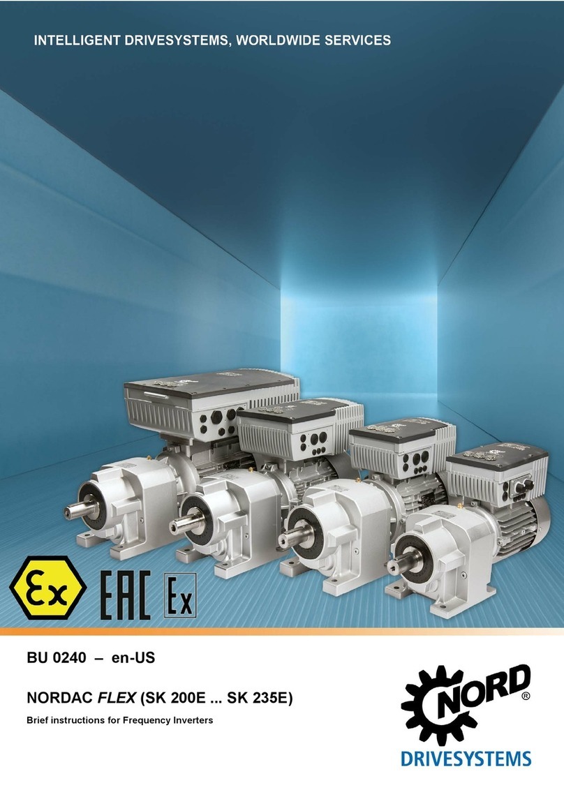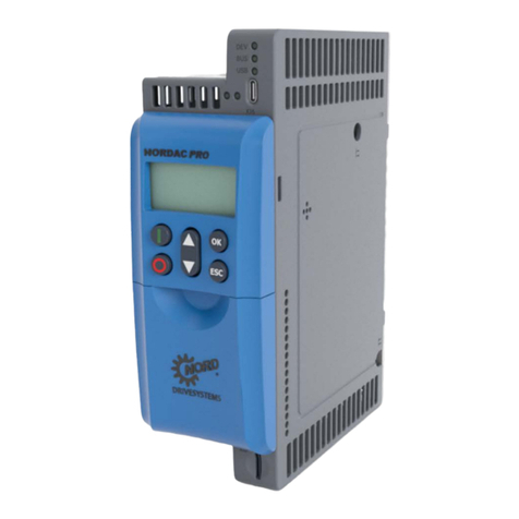
NORDAC FLEX (SK 200E ... SK 235E) – Users Manual for Frequency Inverters
6 BU 0200 en-US-3118
Pos: 10 /Al lg e mei n/S te u erm odul e/In hal ts ver z eic hnis @ 0\mod_1317978518480_14638.docx@ 14771@ @ 1
Table of Contents
=== En de der List e f ür T e xt mar ke I nh alt s ver z eic h nis == =
1General.......................................................................................................................................................11
1.1 Overview ..........................................................................................................................................13
1.2 Delivery............................................................................................................................................16
1.3 Scope of supply ...............................................................................................................................17
1.4 Safety, installation and operating instructions..................................................................................22
1.5 Warnings and hazard information ....................................................................................................27
1.5.1 Warnings and hazard information on the product...............................................................27
1.5.2 Warnings and hazard information in the document ............................................................28
1.6 Standards and approvals .................................................................................................................28
1.6.1 UL and CSA approval.........................................................................................................30
1.7 Model code/nomenclature................................................................................................................32
1.7.1 Nameplate ..........................................................................................................................32
1.7.2 Variable Frequency Drive model code - basic device.........................................................33
1.7.3 Variable Frequency Drive model code - connection unit ....................................................33
1.7.4 Model code for optional modules........................................................................................34
1.7.5 Model code, connection unit for technology unit.................................................................34
1.7.6 Extensions model code ......................................................................................................35
1.8 Output/size assignment....................................................................................................................35
1.9 Version with IP55/IP66 rating...........................................................................................................35
2Mounting and installation.........................................................................................................................37
2.1 Mounting SK 2xxE............................................................................................................................37
2.1.1 Installation of insulating plate – size 4 ................................................................................39
2.1.2Motor installation steps.......................................................................................................40
2.1.2.1 Adapters for motor size 41
2.1.2.2 Dimensions, SK 2xxE mounted on motor 42
2.1.3 Wall mounting.....................................................................................................................43
2.1.3.1 Wall mounting kit without fan 43
2.1.3.2 Wall mounting kit with fan 45
2.1.3.3 Variable Frequency Drive mounting positions with wall mounting kit 47
2.2 Installation of optional modules........................................................................................................48
2.2.1 Optional slots on the device................................................................................................48
2.2.2 Mounting of internal customer unit SK CU4-… (installation)...............................................50
2.2.3 Installation of external technology units SK TU4-… (attachment).......................................51
2.3 Braking resistor (BW) - (from size 1)................................................................................................52
2.3.1 Internal braking resistor SK BRI4-…...................................................................................52
2.3.2 External braking resistor SK BRE4-... / SK BRW4-… / SK BREW4-…...............................55
2.3.3 Braking resistor assignments..............................................................................................57
2.4 Electrical connection ........................................................................................................................58
2.4.1 Wiring guidelines ................................................................................................................59
2.4.2 Electrical connection of power unit .....................................................................................60
2.4.2.1 Power supply connection (L1, L2(/N), L3, PE) 61
2.4.2.2 Motor cable (U, V, W, PE) 63
2.4.2.3 Braking resistor (+B, -B) – (from size 1) 63
2.4.2.4 Electromechanical brake 64
2.4.3 Electrical connection of the control unit ..............................................................................65
2.4.3.1 Power supply unit SK xU4-24V-… - connection example 72
2.5 Color and contact assignments for the incremental encoder (HTL) .................................................74
2.6 Operation in potentially explosive environments..............................................................................75
2.6.1 Operation in potentially explosive environments - ATEX zone 22 3D.................................76
2.6.1.1 Modification of the device for compliance with category 3D 76
2.6.1.2 Options for ATEX zone 22, category 3D 77
2.6.1.3 Maximum output voltage and torque reduction 79
2.6.1.4 Commissioning information 79
2.6.1.5 EU conformity declaration - ATEX 81
2.6.2 Operation in potentially explosive environments - EAC Ex.................................................82
2.6.2.1 Modification of the device 82
2.6.2.2 Further information 83
2.6.2.3 EAC Ex Certificate 83
2.7 Outdoor installation ..........................................................................................................................84


