NORD-LOCK Boltight Typhoon+ User manual
Typhoon+ Hydraulic
Bolt Tensioners
USER MANUAL
Health & Safety Instructions 4Operating Instructions 8Maintenance & Storage 25 Technical Information 27
Boltight Limited
Tel: +44 4(0) 1922 669 222
www.nord-lock.com/boltight

FOREWORD
Thank you for choosing Boltight hydraulic bolt tensioning equipment.
Before using the equipment you are advised to study this manual carefully.
Boltight Limited is an ISO 9001:2015 company and our bolt tensioning equipment has
been designed to comply with the European Pressure Equipment Directive and the UK
Pressure Equipment Regulations and is CE marked and UKCA marked respectively. The
pressures and forces involved with the use of this equipment are high and it is
therefore imperative that users of the equipment read and understand the operating
manual, paying particular attention to the safety information in Section 1.
COPYRIGHT STATEMENT & DISCLAIMER
This Health & Safety, Operating and Maintenance Manual has been prepared by Boltight Limited. All material in this manual is the
property of Boltight and is subject to Copyright. No part of this manual may be copied or reproduced without prior written consent.
Please note that the scope of this document covers the safety, operation and maintenance instructions concerned with the
equipment supplied ONLY. Safe handling, usage and storage of this equipment on customer applications and installations is the
responsibility of the customer. This document should only be considered a part of the customer’s wider procedure for installation
of plant and therefore Boltight cannot accept any responsibility for any actions arising as a result of misuse of this equipment.
The contents of this manual may periodically be subject to alteration. Boltight reserves the right to alter or modify this
manual without prior notification.
Further copies of this manual can be downloaded from the website www.nord-lock.com/boltight

CONTENTS
SECTION 1 – HEALTH & SAFETY INSTRUCTIONS 4
1.1 Safety notes 4
1.2 European Pressure Equipment Directive 5
1.3 Using quick connectors 5
1.4 Hoses 6
1.5 Hydraulic bolt tensioning tools 7
1.6 Personal protective equipment (PPE) 7
SECTION 2 – OPERATING INSTRUCTIONS 8
2.1 Main Component Parts 9
2.2 Recommended practices 9
2.3 Tensioning a bolt 10
2.4 De-tensioning a bolt 17
2.5 Simultaneous bolt tensioning 23
SECTION 3 – MAINTENANCE & STORAGE 25
3.1 Storage 25
3.2 Maintenance 25
3.3 Parts List 26
SECTION 4 – TECHNICAL INFORMATION 27
4.1 Oil pressure calculations 27
4.1 Pressure load graphs 27

SECTION 1 – HEALTH & SAFETY
INSTRUCTIONS
1.1 SAFETY NOTES
Hydraulic bolt tensioning tools are very powerful and capable of inducing very high
bolt stresses. This equipment will give many years of safe tensioning when used in
accordance with these instructions.
Anyone using hydraulic bolt tensioning equipment must be properly trained to use the
equipment and must take adequate steps to ensure their own safety and the health
and safety of others where bolt tensioning operations are being performed. Boltight
can offer training courses either at its UK base or on site anywhere in the world.
Please read the manual before attempting to use the equipment. Do not use the
equipment if you are not already an experienced user of hydraulic bolt tensioning
equipment. Your attention is particularly drawn to the notes in RED.
When using hydraulic bolt tensioners, loads of many
hundreds of tonnes or even thousands of tonnes can
be induced. If the bolt material is incorrect or faulty
or the tool is incorrectly installed, the broken bolt
could be propelled at high speed along the axis of
the bolt. This is a very rare occurrence. If there is a
failure, anyone standing near the bolt tensioning tool
or in line with the axis of the bolt during the
tensioning operation will suffer critical, possibly
fatal, injury. It is therefore essential that anyone
operating this equipment is properly trained and
takes every precaution to ensure that nobody is
allowed to stand, work or stray near to or in line with
the axis of any hydraulic bolt tensioning tool during
the bolt tensioning operation.
At no time should anyone allow any part of their
body to be positioned over the bolt tensioning tool,
whilst the pressure is rising or when it is
pressurised. In the case of studbolts with nuts at
each end it is important that nobody stands in line
with the long axis of the bolt at either end during
the tensioning operation.
Do not approach a bolt tensioning tool whilst it is
being pressurised. Remember a damaged bolt or
tool is most likely to fail at this critical time. When
the operating pressure has been reached, approach
a pressurised bolt tensioning tool only for as long as
it takes to turn the permanent nut always keeping
away from the axis of the bolt and the bolt
tensioning tool.
Bolt Tensioning tools MUST always be used with a
hydraulic pump which has a pressure limiting
device. Always check that the pump stall pressure
is set at or below, the maximum working pressure
for the tool being used.
Clear all personnel from the area where the bolt
tensioning operation is to be performed. Position
the pump a safe distance away from the bolt
tensioning tools. Set up barriers and warning signs,
or make other adequate arrangements to prevent
unauthorised personnel from accidentally straying
into the bolt tensioning area.
Never leave a pressurised bolt tensioning tool
unattended. Keep the bolt tensioning tools under
pressure for the minimum time necessary to
complete the bolt tightening job. The tools should
only be used as a bolt tensioning tool. DO NOT use
the tools as hydraulic jacks or for any other purpose.
Take care when handling the tools. Large tools may
be heavy and require the use of lifting equipment.
The bridge and load cell of the larger tools are not
held together. The load cell and bridge are easily
taken apart.
Do not try to tighten a leaking hydraulic connection
when it is under pressure. First release the pressure
then repair the leak.
4HEALTH & SAFETY INSTRUCTIONS IBOLTIGHT – TYPHOON+ USER MANUAL
1
4
2
5
3
6
DO NOT pressurize the connectors
when they are disconnected.
Check that there is no pressure in
the system before attempting to
connect or disconnect the couplings.
1.2 EUROPEAN PRESSURE EQUIPMENT DIRECTIVE
The Typhoon+ range of hydraulic bolt tensioners are designed to operate at pressures up to 1350 bar
with Group 2 liquid (hydraulic oil ISO 32 or ISO 46) with a volume less than 10 litres. This equipment
aligns with:
• Category 1:- 2014/68/EU European Pressure Equipment Directive
• Category 1:- UK Pressure Equipment (Safety) Regulations 2016.
Under these regulations the equipment must therefore:
a) be safe;
b) meet the essential safety requirements covering design, manufacture and testing;
d) be accompanied by adequate instructions for use;
e) be marked to identify the manufacturer and CE marked and the UKCA mark respectively.
The regulations call for pressure equipment to be pressure tested at 1.43 times the maximum pressure.
However the regulations recognise that in some cases this may be harmful or impractical. Due to the
very high bolt stresses developed, it is impractical to pressure test the equipment at 1.43 times the
maximum pressure. It would also be harmful to the seals if the equipment was tested at these
pressures. All equipment has been tested to 1.1 times the maximum pressure where appropriate and a
test certificate has been issued.
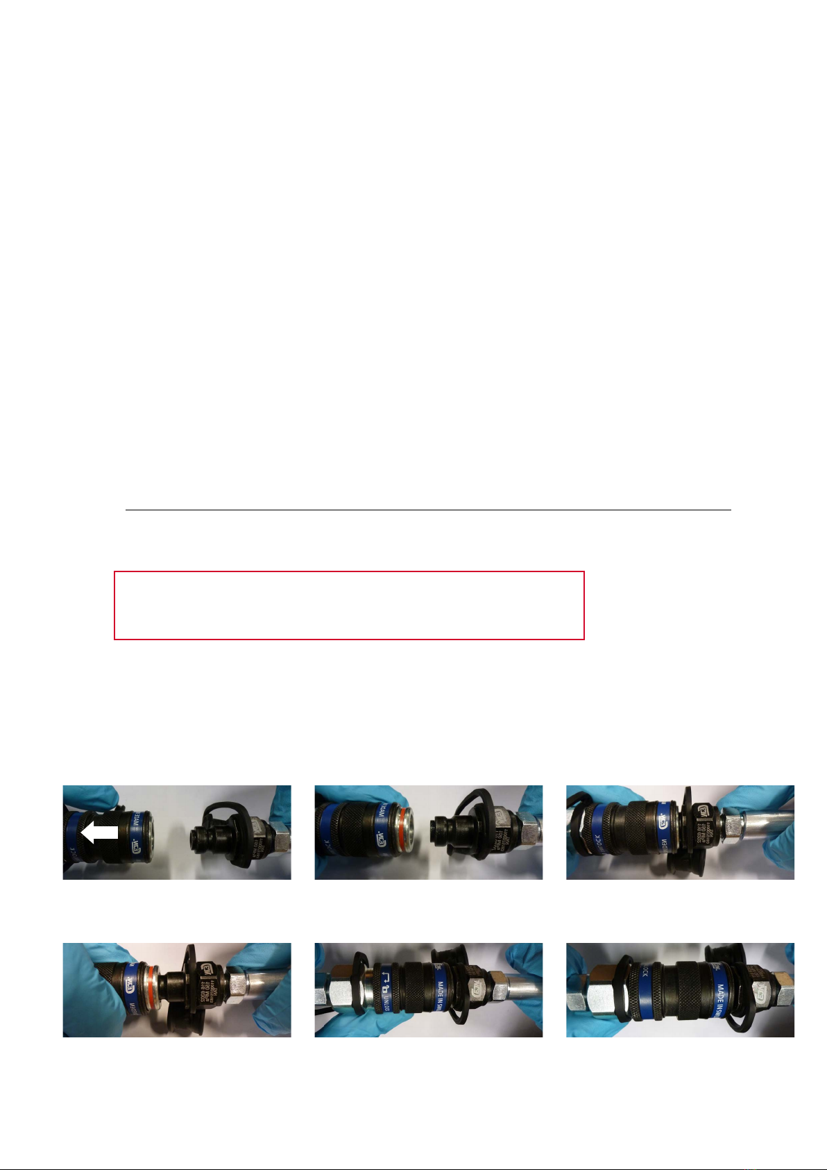
1.3 USING QUICK CONNECTORS
To connect the quick connect coupling and nipple, first check there is no pressure in the system.
Pull back the shroud by hand and push the coupling onto the nipple. When together, release the
shroud which will spring back to connect the coupling and nipple together. The coupling should
now be locked using the safety locking sleeve (SLS). To disconnect, again check there is no
pressure in the system. Pull back the shroud by hand, and pull the coupling and nipple apart. Once
apart release the shroud.
Pull the shroud into the retract position Insert the nipple into the coupling whilst
the shroud is in the retract position
Allow the shroud to spring back into the
forward position
Check the red line is not visible – if red
line is visible the connection is not safe
to use
To close the safety locking sleeve (SLS)
push the shroud forward to the back of
the collar and rotate – release to lock
This image shows the SLS in the locked
position – this joint is now safe to use
5BOLTIGHT – TYPHOON+ USER MANUAL IHEALTH & SAFETY INSTRUCTIONS

1.4 HOSES
Boltight supply flexible hydraulic hoses which have a small plastic core tube surrounded by multiple high
tensile steel spiral windings. The outside of the hose is molded with a coloured plastic coating. Most hoses
also have a clear plastic cover which provides additional protection against damage when in use. Each hose
is identified with a serial number. All hoses are pressure tested and test certificates are issued.
Three types of hose are available which are identified by the colour of the molded plastic coating beneath the
clear plastic cover. The maximum working pressure for the hose is sometimes marked on the outside of the
coloured plastic coating; however this is the working pressure of the hose ONLY and not the hose ASSEMBLY.
The maximum working pressure of a hose assembly is often limited by the pressure rating of the quick
connect couplings and/or the fittings on the end of the hose. Although the hose may be capable of operating
at higher pressures the limit you must observe is shown below along with the minimum bend radius.
COLOUR MAX WORKING PRESSURE MIN BEND RADIUS
GREEN 1000 bar 95 mm
BLUE 1500 bar 130 mm
RED 2500 bar 200 mm
Hoses are fitted with self sealing quick connect couplings at one or both ends.
If in doubt contact your representative for further information.
— Discard and do not use any hose that does not
have an identifying serial number.
— Discard and do not use any hose that shows
any sign of damage:
-to the coloured molded plastic coating;
-where the spiral windings are exposed;
-where the spiral windings are damaged
or broken;
-where there is damage to the swaged
metal ends;
-do not allow any hose to be kinked
or knotted.
— Hoses which have been kinked or knotted will
have suffered damage and must be discarded.
— Do not allow heavy objects to fall on, rest on, or
roll over the hoses.
— Do not allow hoses to be subjected to
temperatures higher than 60°C.
— Discard and do not use any hose which has
been subjected to heat or fire.
— Do not bend the hose tighter than the minimum
bend radius of the hose or it will be kinked.
— Do not exceed the maximum working pressure
of the hoses.
— Only use the hoses for their intended purpose –
for use with Boltight hydraulic equipment.
— After use check the hoses for damage, wipe to
remove dirt and oil, refit dust caps and prepare
for storage.
— When not in use store the hoses in a safe place
where they cannot easily be damaged.
— Do not mix the coloured hoses. The end fittings
/quick disconnect couplings have different
pressure ratings.
— Never move hose end connectors or quick
disconnects from one colour hose to another.
— All Boltight tools are marked with maximum
operating pressure - ensure tools are
compatible with the hoses you are using.
— Never use the hoses as a handle to carry or pick
up the bolt tensioning tools.
YOU MUST OBSERVE THE FOLLOWING HEALTH & SAFETY
INSTRUCTIONS WHEN USING HYDRAULIC HOSES:
6HEALTH & SAFETY INSTRUCTIONS IBOLTIGHT – TYPHOON+ USER MANUAL
1.5 HYDRAULIC BOLT TENSIONING TOOLS
This can be found etched directly onto the tensioner, on
the general assembly drawing for the tensioner or the
pressure vs load graph. The bolt being tensioned may
have a maximum load less than that generated by the
tensioner at maximum working pressure. The operator
needs to confirm and check what the maximum
pressure is for the particular application being
tensioned. See Section 4 for more information.
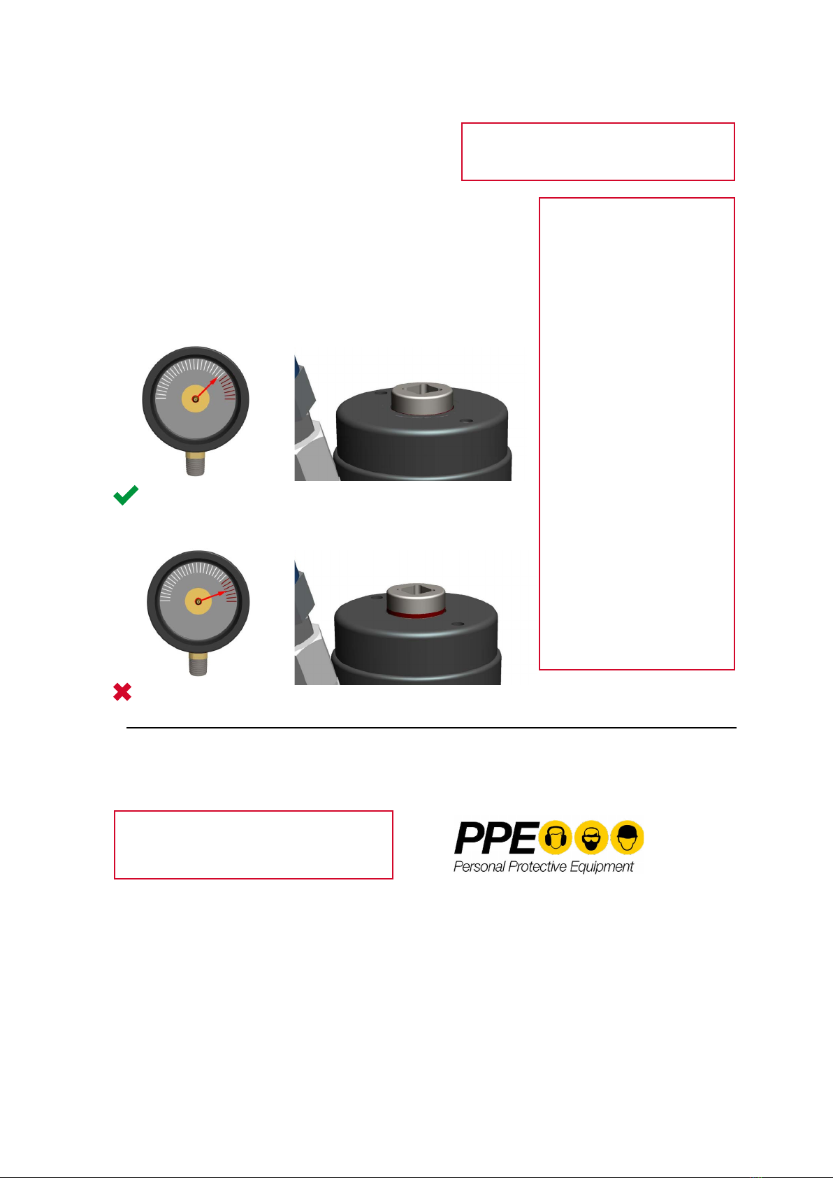
Maximum pressure Do not exceed the maximum working
pressure.
The operator is alerted that
maximum stroke has been
achieved by the indicator ring
which is mounted in the shaft
of the puller bar.
When the tool reaches
maximum stroke -when this
indicator is visible to the
operator, the operator should
stop the pump and tighten the
nut. No further benefit is
gained by increasing the
pressure at maximum stoke
as the bolt cannot be
stretched any further.
See Section 4 for more
information on pressure vs
initial bolt stress graph. The
tooling has been issued with a
pressure/load certificate.
Never exceed the tested load
or pressure, whichever is
lower.
1.6 PERSONAL PROTECTIVE EQUIPMENT (PPE)
This equipment includes (but is not limited to):
— eye protection;
— gloves;
— overalls;
— hard hat;
— steel toe-capped boots or shoes;
— any other site specific PPE required.
When using bolt tensioning tools the operator
should ensure that they are wearing the
correct Personal Protective Equipment (PPE).
<= Maximum
> Maximum
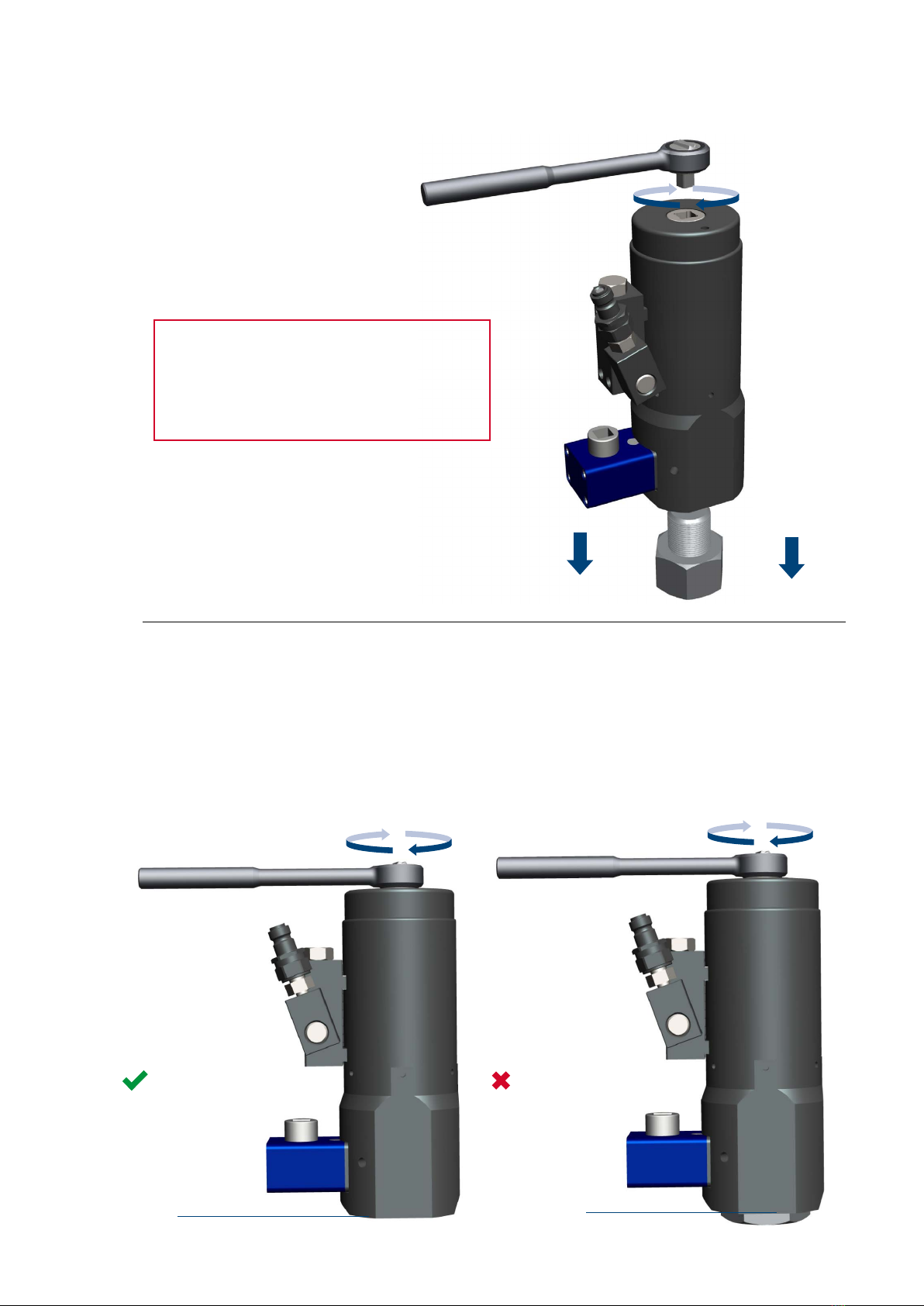
CORRECT AND SAFE
WRONG AND DANGEROUS
Indicator ring visible. Stop the pump.
Indicator ring not visible. Stroke available.
7BOLTIGHT – TYPHOON+ USER MANUAL IHEALTH & SAFETY INSTRUCTIONS

SECTION 2 – OPERATING INSTRUCTIONS
Introduction
A hydraulic bolt tensioner is simply an annular jack with a hollow bore. Much like a jack, a
hydraulic pushing force is generated, however instead of lifting a heavy object the force is
transferred into stretching a bolt. To allow the transfer of force into the bolt a hydraulic
tensioner utilises a threaded puller, bridge and nut rotating socket to effectively transfer and
lock in the tensioned load within a joint.
Unlike conventional tightening methods bolt tensioning does not use torque and does not
require any forceful turning of the nut or bolt, like impact wrenches, flogging spanners or
hydraulic torque wrenches. All of these methods have one common limitation, FRICTION.
Friction accounts for up to 80% of the energy lost when torque tightening a joint, giving only
20% transferable energy for bolt tension.
Bolt tensioning tools can be grouped together to enable multiple bolts to be tightened
simultaneously, to the same high and accurate pre-load. This is particularly useful when
compressing gaskets in pipeline or pressure vessel flanged connections. The high load
developed from the multiple bolt tensioning tools, is evenly distributed around the joint causing
the gasket to flow into the surface irregularities of the flange giving a much better seal.
Flexible hoses with self sealing quick connect couplings are used to group the bolt tensioning
tools together to form a hydraulic ring main. The ring main and tensioning tools are
pressurised using an air driven pump working from a compressed air supply or an electric
pump.
IMPORTANT NOTICE
The tools feature a safe failure mechanism. In the event that the fatigue life of the tool expires, it
has been engineered to fail safely and remain in-situ upon the bolt, posing no threat to adjacent
personnel or equipment.The maximum tool pressure cycle is indicated with the tool technical data.
A record of pressure cycles should be kept and the tool returned for puller replacement before
reaching this limit. A cycle counter can be fitted to the tensioner, to assist with quantifying the
number of cycles the tool has experienced.
The tools are subjected to a one-off pressure test prior to despatch, and a test certificate issued to
certify this. PLEASE NOTE this is not tested at the maximum operating pressure and it is strongly
advised that the tool is NEVER operated above its maximum. Re-testing is not required during its
working life, even after fitting new seals. If the user wishes to conduct a pressure test, the
tensioner should returned to the manufacturer for recertification.
Tool Description
The pressure equipment covered by this operating manual is a Typhoon+ Multi-Stage hydraulic
bolt tensioning tool. The Typhoon+ multi-stage range has been engineered to provide
maximum load capacity under minimal radial envelope conditions.
A multi-stage bolt tensioning tool comprises axially-stacked interlocking load cells (each
comprising a body, piston and inner/outer seal), a common central puller (comprising a
reaction nut and 1/2” drive socket), a spring retraction system and interconnecting bridge. The
bridge incorporates a gear-driven nut rundown mechanism for convenience, also incorporating
a ½” drive socket. The tensioner incorporates a mechanical anti-overstroke protection facility,
and also features a maximum stroke indicator. The load cells are pressurised simultaneously
via a radially mounted manifold block of vertical CEJN 116 nipple configuration.
The different sizes of multi-stage tools have different maximum strokes. Refer to the
information in Section 4 to confirm the maximum stroke, operating pressure and maximum
force for the equipment.
The tensioner must not be modified by any type of machining and no attachment can be made
to the tools by any form of welding or brazing.
8OPERATING INSTRUCTIONS IBOLTIGHT – TYPHOON+ USER MANUAL

1
2
3
4
6
2.1 MAIN COMPONENT PARTS
1 Hydraulic load cells
A multi-stage bolt tensioning tool comprises axially-stacked
interlocking load cells (each comprising a body, piston and
inner/outer seal), a common central puller (comprising a
reaction nut and 1/2” drive socket) and a spring retraction
system.
The load cells are pressurised via a radial manifold block,
using a CEJN 116 high pressure nipple. Within the tensioner,
the hydraulic load cells are interlocked for simultaneous
pressurisation and are supported by the bridge.
2Spring actuated piston
The tool features a spring actuated piston return facility. The
spring retraction system comprises heavy duty springs, which
are contained within the spring cap. The spring system should
not require attention during the working life of the tool. When
the pressure within the tool is returned to zero the spring force
will retract the pistons fully back into the outer bodies.
3 Seals
Each cell is fitted with red polymer lip seals with an anti-
extrusion ring.
4Bridge
The bridge incorporates a spring-loaded gear-driven nut
rundown mechanism for convenience, also incorporating a ½”
square drive socket.
5 Gear Driven socket
The gear driven socket within the bridge has been designed to
interface snugly with the across flats dimensions of nuts as
supplied by the customer, and nut rundown following
pressurisation is achieved by rotating the gear driven socket.
This is performed via the ½” square drive socket located at the
top of the gearbox. This gearbox and geared socket
mechanism can also be utilised to unwind nuts during de-
tensioning procedures.
6Nut and Bolt
Tensioners can be used with standard hex nuts, large width
hex nuts, round nuts or special nuts. The correct tool must be
selected in accordance with the application.
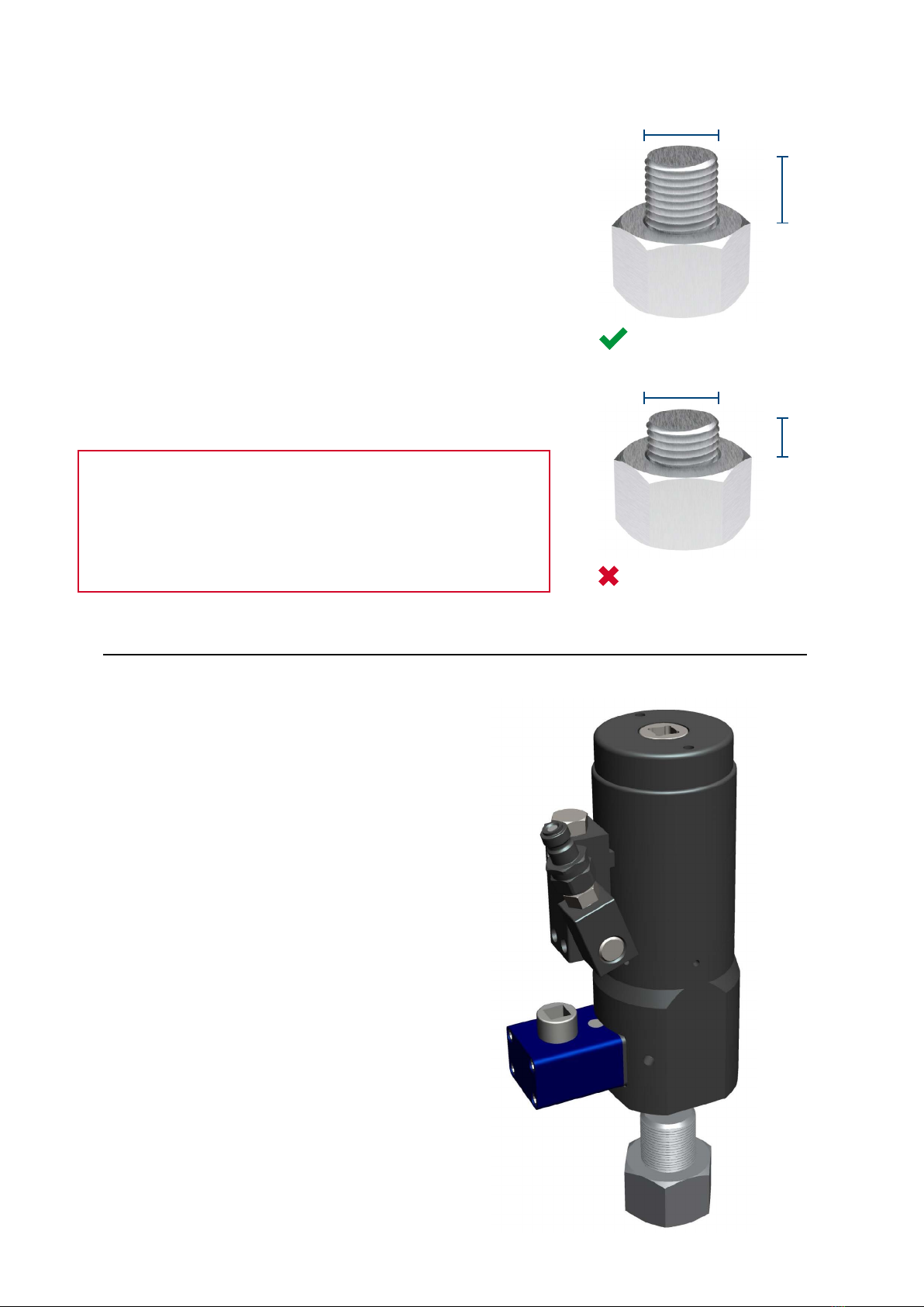
An extra length of thread must protrude through the nut for the
tensioner to screw onto and apply the bolt tension. The length
of the bolt is very important. Details are given in Section 2.3
Step 1. NOTE: Good quality bolts and nuts will make the
tensioning operation quicker and more accurate.
2.2 RECOMMENDED PRACTICES
To obtain the best results from your hydraulic bolt tensioning equipment you should carefully follow the
operating instructions given in the following pages. You should also observe the instructions given below.
DO NOT Do not try to pressurise the hydraulic tensioner unless it is properly seated on its bridge, the bridge
is in full contact with the application and the puller bar has been correctly engaged onto the bolt to be
tightened or released else the tensioner may be damaged beyond safe or repairable use.
9BOLTIGHT – TYPHOON+ USER MANUAL IOPERATING INSTRUCTIONS
Step 1
Please follow all safety instructions set out in Section 1. Ensure the
joint has been assembled using the correct nuts and bolts required
for tensioning.
To ensure the safe and effective use of the hydraulic bolt tensioner
ensure that a minimum of 2 x bolt diameters of bolt length is
protruding from the surface of the joint face. Bolt protrusion
should not exceed maximum stated on general arrangement
drawing.
It is imperative that the correct bolt length is available prior to the
hydraulic tensioner activation as failure to do so may result in the
threads stripping off the bolt and the bolt tensioner puller bar.
2.3 TENSIONING A BOLT
HEALTH & SAFETY WARNING
If only a few threads protrude and an attempt is made to apply
tension the bolt threads will strip and components of the tensioner
could be propelled with the possibility of serious injury and may
cause damage to the bolt and tensioner.
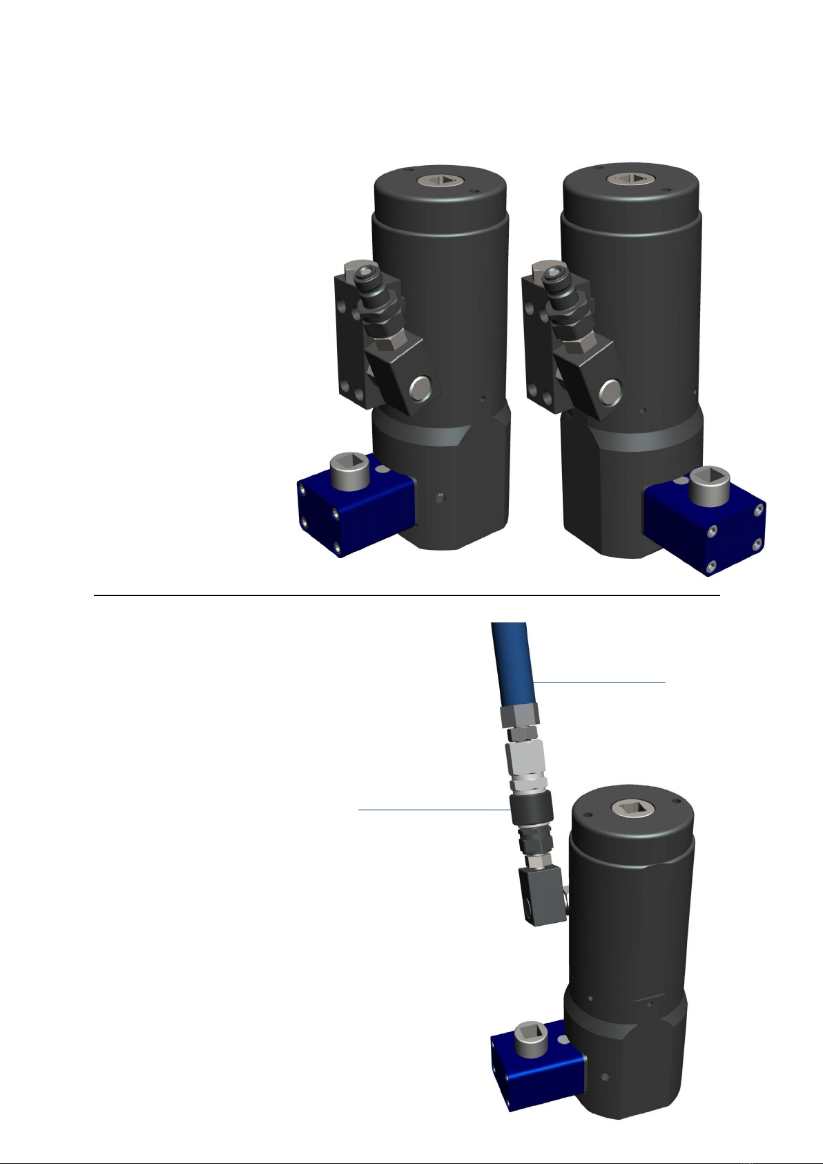
Step 2
Position the Tensioner over the bolt to be tightened.
Position the tensioner so that manifold is accessible,
and such that the bridge allows access to the gear box.
CORRECT AND SAFE
WRONG AND DANGEROUS
D
≥ D
< D
D
10 TENSIONING A BOLT IBOLTIGHT – TYPHOON+ USER MANUAL
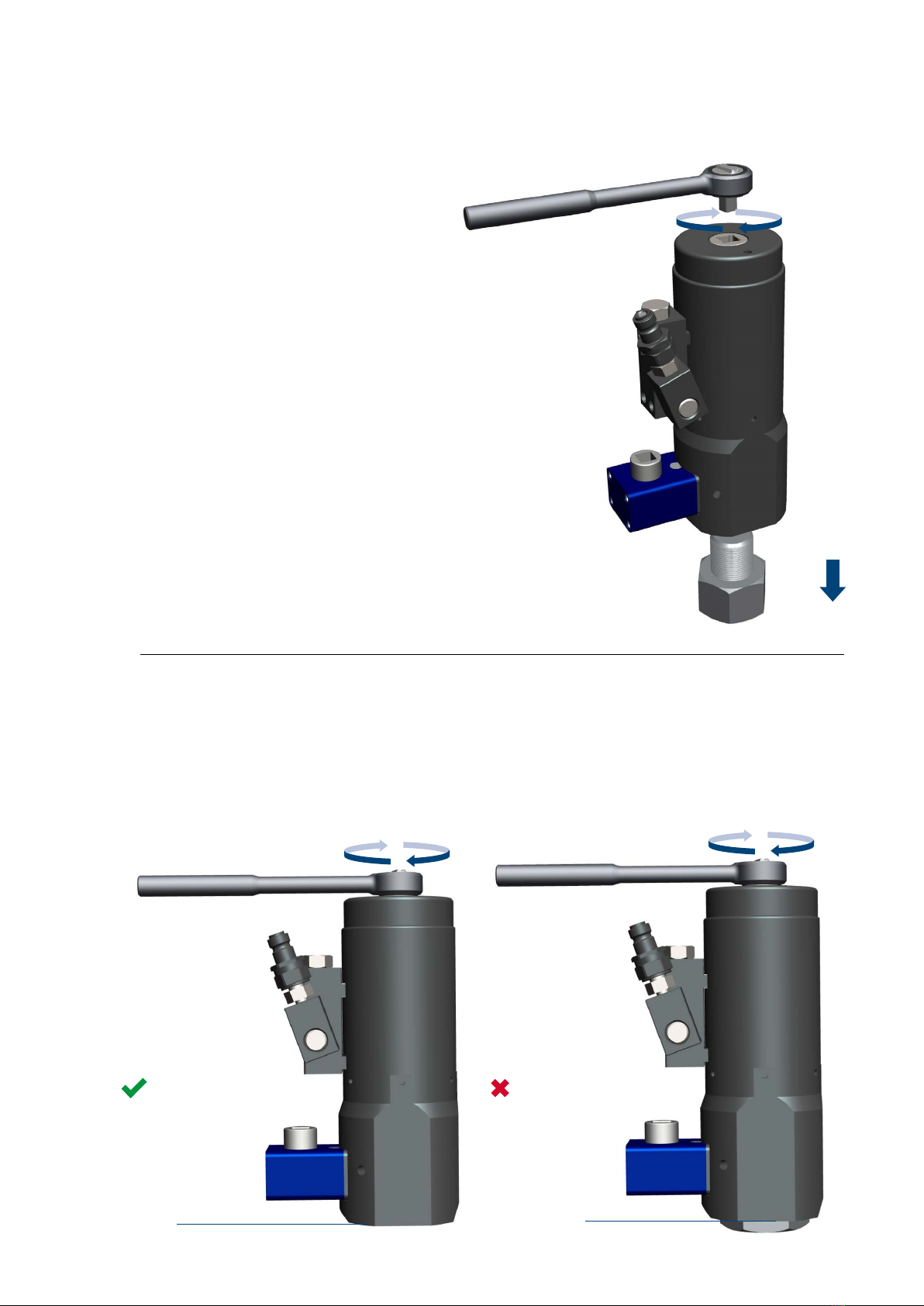
Step 4
Continue rotating the puller bar, increasing its engagement with the bolt until the bridge is flush
with the application surface. To ensure the tool is fully flush, it may be necessary to rotate the
gearbox slightly whilst lowering to fully engage the gear driven socket with the nut. Make sure
that the bridge is seated on a flat and level surface and avoids any adjacent nuts or application
obstructions.
Step 3
Engage the puller bar with the bolt. A ½”
square drive socket is provided - insert
into the top of the puller bar so that the
tensioner orientation can be maintained
whilst the puller bar engages the bolt.
FLUSH
CORRECT AND SAFE
NOT FLUSH
WRONG AND DANGEROUS
11BOLTIGHT – TYPHOON+ USER MANUAL ITENSIONING A BOLT
Step 5
Once the tensioner is in situ, it should still be
possible to rotate the bridge to a suitable
angle to access the bolt if required.
Step 6
Connect the tensioner to corresponding hydraulic
hose and pump unit.
Make sure the quick connect coupling is fully
engaged. See Section 1.3.
HYDRAULIC HOSE
QUICK CONNECT COUPLING
12 TENSIONING A BOLT IBOLTIGHT – TYPHOON+ USER MANUAL
TENSIONING A BOLT – HEALTH & SAFETY
The bolt tensioning tool is now ready to be pressurised. Before proceeding read the Health
& Safety Instructions given in Section 1 of this manual then proceed as follows:
— Ensure suitable PPE has been utilised prior to pressurisation.
— Clear all personnel from the area where the bolt tensioning operation is to be
performed. Position the pump a safe distance away from the bolt tensioning tools. Set
up barriers and warning signs, or make other adequate arrangements to prevent
unauthorised personnel from accidentally straying into the bolt tensioning area.
— Release the oil pressure immediately if any unauthorised person moves into the bolt
tensioning area and especially is anyone stands in front of a bolt tensioning tool under
pressure or stands in line with the long axis of a bolt being tensioned.
— Determine the correct working pressure for the bolts to be tightened. Proceed with the
following operations keeping the bolt tensioning tools under pressure for the minimum
time necessary to complete the bolt tightening operation.
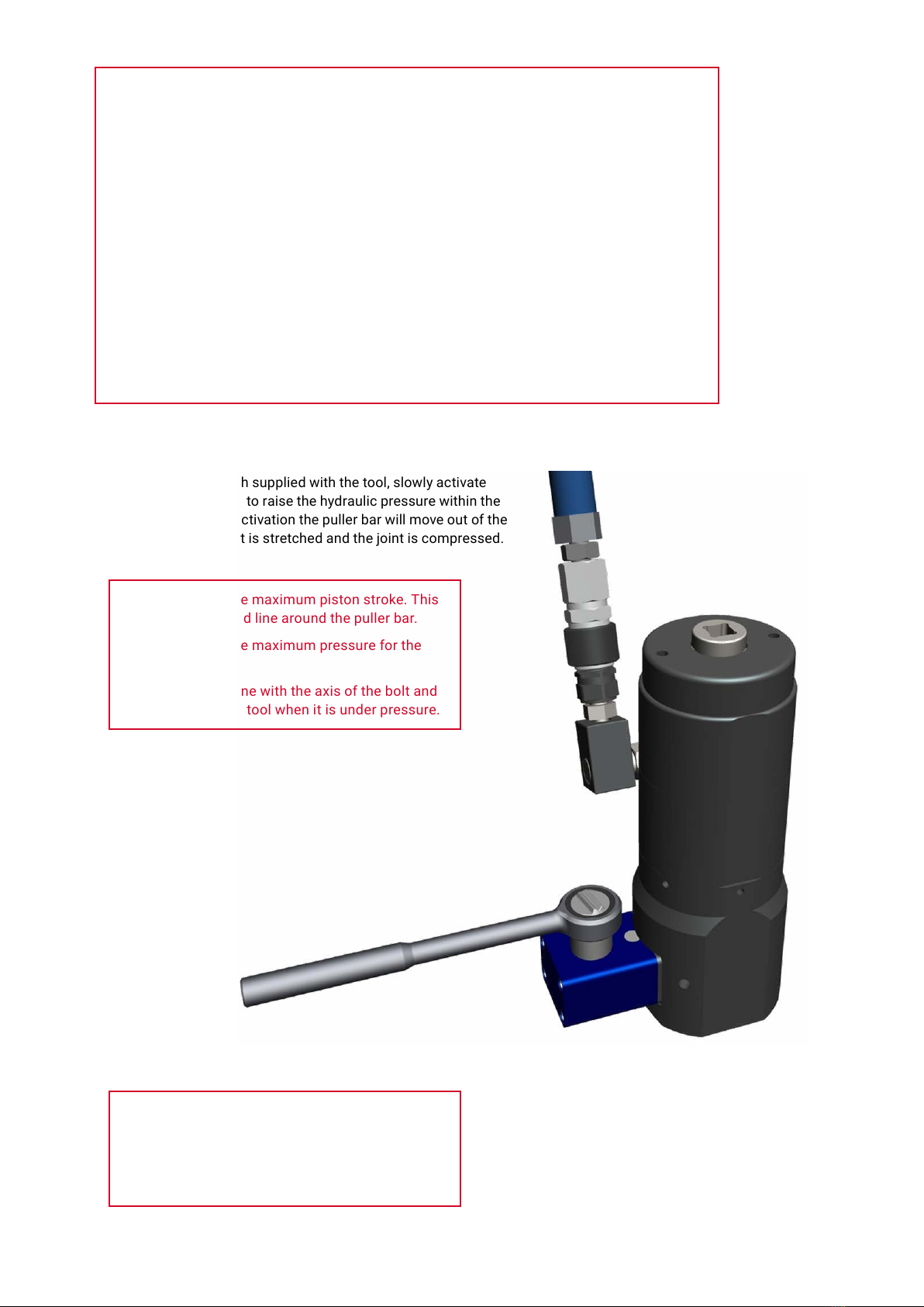
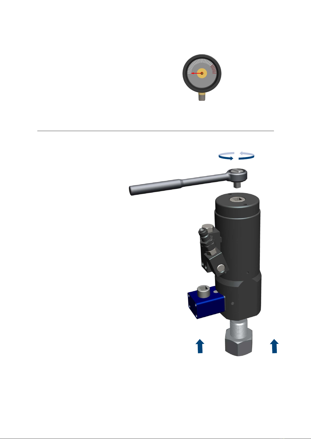
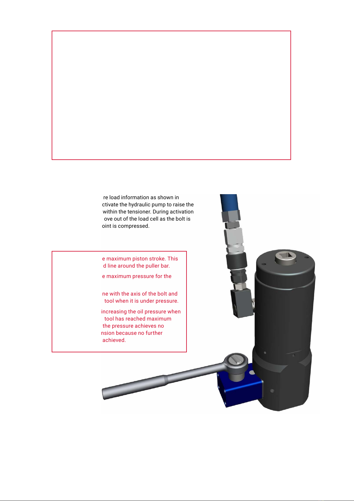
Step 7
Utilising the pressure load information as shown on the
pressure load graph supplied with the tool, slowly activate
the hydraulic pump to raise the hydraulic pressure within the
tensioner. During activation the puller bar will move out of the
load cell as the bolt is stretched and the joint is compressed.
DO NOT exceed the maximum piston stroke. This
is indicated by a red line around the puller bar.
DO NOT exceed the maximum pressure for the
tool.
DO NOT stand in line with the axis of the bolt and
the bolt tensioning tool when it is under pressure.
If the indicator shows the tensioner has reached
maximum stroke before the correct hydraulic pressure
has been achieved, stop the pump and proceed as
follows :-
Tighten the Nut
Release the Pressure
Allow the tensioner to retract fully
Reengage the tool
Apply the correct Pressure
If necessary repeat this sequence until the bolt
tensioning tool reaches the correct oil pressure
without reaching the maximum piston stroke.
DO NOT continue increasing the oil pressure when
the bolt tensioning tool has reached maximum
stroke. Increasing the pressure achieves no
increase in bolt tension because no further
elongation can be achieved.
13BOLTIGHT – TYPHOON+ USER MANUAL ITENSIONING A BOLT

Step 8
Using a ½” square drive socket insert into drive hole
situated on the top of the gearbox. Rotate the until
the nut is firmly seated on the application.
Step 9
Slowly release the hydraulic pressure by opening the
pressure release valve on the hydraulic pump.
The spring return system will now fully retract the
tensioning tool. The top of the puller bar will be flush with
the spring cap at zero stroke.
DO NOT disconnect the hose from the tensioner as this
will prevent the tool from retracting.
14 TENSIONING A BOLT IBOLTIGHT – TYPHOON+ USER MANUAL
Step 10
The Tensioner will have retracted upwards as the bolt will have
elongated. The tool will need reengaging onto the flange. Using
the ½” square drive socket, reengage the puller onto the stud
until the tool is flush with the flange.
FLUSH
THEN ONE ADDITIONAL
HALF TURN
NOT FLUSH
Step 11
Apply the correct hydraulic pressure and
wind the nut clockwise again once this
is achieved.
Do not exceed the maximum working
pressure for the tool.
The operator is alerted that maximum stroke
has been achieved by the indicator ring which
is mounted in the shaft of the puller bar.
15BOLTIGHT – TYPHOON+ USER MANUAL ITENSIONING A BOLT
Step 12
Slowly release the hydraulic pressure by opening the
pressure release valve on the hydraulic pump’
The spring return system will now fully retract the
tensioning tool. The top of the puller bar will be flush with
the spring cap at zero stroke.
DO NOT disconnect the hose from the tensioner as this
will prevent the tool from retracting.
Remove the hose once the stroke has returned to zero.
Step 13
Turning anti-clockwise remove the tensioner
using the ½” square drive socket in the top of
the puller.
16 TENSIONING A BOLT IBOLTIGHT – TYPHOON+ USER MANUAL

Step 1
De-tensioning of a bolt follows many of the steps as shown in the
previous section. There are however a few key differences in the
process which are explained within the following section.
Follow all safety instructions set out in Section 1 then visually
inspect the bolts to be de-tensioned. To ensure the safe and
effective use of the hydraulic bolt tensioner ensure that a minimum
of 2 x bolt diameter of bolt length is protruding from the surface of
the joint face. Bolt protrusion should not exceed maximum stated
on general arrangement drawing.
It is imperative that the correct bolt length is available prior to the
hydraulic tensioner activation as failure to do so may result in the
threads stripping off the bolt and the bolt tensioner puller bar.
Next ensure that the threads are clean and have not been
damaged. Any damage to the threads should be rectified with a
thread file or die nut before attempting to assemble the hydraulic
bolt tensioning tool onto the bolt.
2.4 DE-TENSIONING A BOLT
HEALTH & SAFETY WARNING
If only a few threads protrude and an attempt is made to apply
tension the bolt threads will strip and components of the tensioner
could be propelled with the possibility of serious injury and may
cause damage to the bolt and tensioner.
CORRECT AND SAFE
WRONG AND DANGEROUS
D
≥ D
< D
D
Step 2
Position the tensioner over the bolt to be loosened.
Position the tensioner so that manifold is accessible,
and that the bridge allows access to the gear box.
17BOLTIGHT – TYPHOON+ USER MANUAL IDE-TENSIONING A BOLT
Step 4
Continue rotating the puller, increasing its engagement with the bolt until the
bridge is flush with the application surface. To ensure the tool is fully flush, it
may be necessary to rotate the gearbox slightly whilst lowering to fully
engage the gear driven socket with the nut. Make sure that the bridge is
seated on a flat and level surface and avoids any adjacent nuts or application
obstructions. Ensure the bridge does not largely overhang or react off uneven
surfaces.
FLUSH
CORRECT AND SAFE
NOT FLUSH
WRONG AND DANGEROUS
Step 3
Engage the puller bar with the bolt. A ½”
square drive socket is provided - insert
into the top of the puller bar so that the
tensioner orientation can be maintained
whilst the puller bar engages the bolt.
During the rotation of the puller, ensure that
the bolt remains stationary as failure to do
so could result in a reduced thread
engagement in both the puller or application.
18 DE-TENSIONING A BOLT IBOLTIGHT – TYPHOON+ USER MANUAL

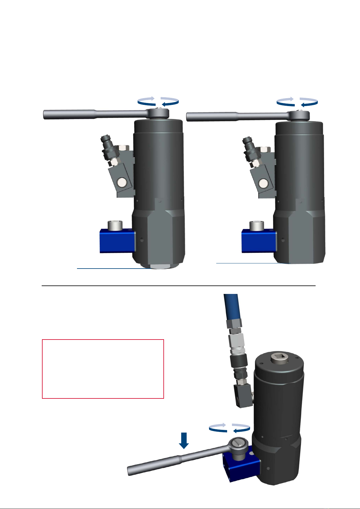
Step 5
Now rotate the Puller ANTI-CLOCKWISE BY
HALF A TURN
This is to prevent the Tensioner from locking
onto the stud. This will raise the tensioner
slightly so the bridge is no longer flush with
the application surface.
Once the Tensioner is in situ, it should still be
possible to rotate the bridge to a suitable angle to
access the bolt if required.
ANTI-CLOCKWISE
HALF A TURN
Step 6
Connect the tensioner to corresponding hydraulic
hose and pump unit.
Make sure the quick connect coupling is fully
engaged. See Section 1.3.
HYDRAULIC HOSE
QUICK CONNECT COUPLING
19BOLTIGHT – TYPHOON+ USER MANUAL IDE-TENSIONING A BOLT
Step 7
Utilising the pressure load information as shown in
Section 4, slowly activate the hydraulic pump to raise the
hydraulic pressure within the tensioner. During activation
the puller bar will move out of the load cell as the bolt is
stretched and the joint is compressed.
DO NOT exceed the maximum piston stroke. This
is indicated by a red line around the puller bar.
DO NOT exceed the maximum pressure for the
tool.
DO NOT stand in line with the axis of the bolt and
the bolt tensioning tool when it is under pressure.
DO NOT continue increasing the oil pressure when
the bolt tensioning tool has reached maximum
stroke. Increasing the pressure achieves no
increase in bolt tension because no further
elongation can be achieved.
TENSIONING A BOLT – HEALTH & SAFETY
The bolt tensioning tool is now ready to be pressurised. Before proceeding read the Health
& Safety Instructions given in Section 1 of this manual then proceed as follows:
— Ensure suitable PPE has been utilised prior to pressurisation.
— Clear all personnel from the area where the bolt tensioning operation is to be
performed. Position the pump a safe distance away from the bolt tensioning tools. Set
up barriers and warning signs, or make other adequate arrangements to prevent
unauthorised personnel from accidentally straying into the bolt tensioning area.
— Release the oil pressure immediately if any unauthorised person moves into the bolt
tensioning area and especially is anyone stands in front of a bolt tensioning tool under
pressure or stands in line with the long axis of a bolt being tensioned.
— Determine the correct working pressure for the bolts to be tightened. Proceed with the
following operations keeping the bolt tensioning tools under pressure for the minimum
time necessary to complete the bolt tightening operation.
20 DE-TENSIONING A BOLT IBOLTIGHT – TYPHOON+ USER MANUAL
Table of contents
Other NORD-LOCK Industrial Equipment manuals

Popular Industrial Equipment manuals by other brands


oventrop
oventrop Regudis W Installation passport

Tekelec
Tekelec EAGLE 5 Commands Error Recovery Manual

HEIDENHAIN
HEIDENHAIN M12 Mounting instructions

schmalenberger
schmalenberger fluvo CG700 rondo operating instructions

ITW Dynatec
ITW Dynatec DYNAMINI 4-HOSE Technical documentation

CRH
CRH Leviat HALFEN HDB-Z Assembly instructions