CRH Leviat HALFEN HDB-Z User manual

®
Assembly Instructions •Montageanleitung • Notice d‘utilisation • Instrukcja montażu
HALFEN HDB-Z INST_HDB-Z 01/21
D
F
Durchstanzbewehrung
für Fundamente
Armature de poinçonnement
pour fondations
Punching Shear Reinforcement
for Foundations
Zbrojenie na przebicie
dla fundamentów
GB
I
NST
_H
DB-Z 0
1/
2
1
b
ewehrun
g
e
nt
e
e
poinçonnemen
t
ion
s
h
ear Rein
f
orcement
ion
s
a
prze
b
icie
en
tó
w
PL

2© 2021 · INST_HDB-Z 01/21 · www.halfen.com
HALFEN HDB-Z Assembly Instructions
Deutsch EnglishFrançaisPolski
The HALFEN HDB-Z Elements are
approved by the DIBt*Berlin as punching
shear reinforcement for use in foundation
slabs and in pad foundations.
Approval no. Z-15.1-330.
Zul.-Nr.
Z-15.1-330
DIBt
A
E
C
D
Type classification
The HDB-Z Punching shear elements are manufactured
according to the specifications provided by the customer in
accordance with National Technical Approval no. Z-15.1-330.
These instructions apply to all types of HDB-Z. To ensure the
HDB-Z Punching shear reinforcement stays fixed in position,
the supplied spacers must be attached under the bar at the
bottom bend and to the end of the rear support T-bar.
DIBt* = Deutsches Institut für Bautechnik. German Institute of Construction Engineering
Order example: Dimensions in [mm] HDB-Z - 12 - 400 - 30 - 30
Product type
Anchor diameter Ø (A)
Footing (foundation slab) height hfooting (E)
Upper concrete cover cnom,o (C)
Bottom concrete cover cnom,u (D)
Spacers
Simple installation: The fibre cement spacer is slotted onto the end of the rear support bar
Spacer Fitting the spacer Final state before installing
the elements
Fitting the front spacers
Fibre cement spacer Wire-tie/fixing to the bottom bend Final state before installing
the elements
Cnom,u
(Standard
50mm)
20
35
H
(Standard
70mm)
Cnom,u

3
© 2021 · INST_HDB-Z 01/21 · www.halfen.com
HALFEN HDB-Z Assembly Instructions
Deutsch EnglishFrançaisPolski
Align the HDB-Z Elements using an auxilliary length of rebar
According to approval Z-15.1-330, it is not
permitted to use different diameters of
HDB-Z at one column!
Installation
The point of
measurement is
defined by the
vertical tangent of
the bending roll
diameter.
Point of measurement/
vertical tangent
For easy aligning, a length of
rebar is placed on the clamping
plate and pressed into the rear-
bend as shown. The correct
position of the element is checked
using a plumb line. See illustration.
We recommend this is done on
both sides of the HDB-Z element.
T-bar
T-bar
Cnom,u
Bend
Clamping plate
Element with correctly installed spacers — ready for
installation on a subbase or formwork Do not install the HDB-Z
Elements on the reinforcement
bars. The T-bar should always
be perpendicular, and the
clamping plate should always
be installed horizontal.
Ensure the longitudinal
reinforcement can be passed
over and across the lower
bend of the punching shear
zone on-site.
We advise against using
reinforcement mesh in the
punching shear area.
To ensure quick and error-free installation, the installation sequence shown on page 5 must be followed!
Leading edge
of the bolt
head
It is strictly recommended to use the
supplied spacers for installation.
plumb line/or spirit level
Auxilliary length of rebar
When placing the first row of HDB-Z
elements, the leading edge of the head
bolt must be aligned with the defined
marking for the column edge.
The second row must be placed at 0.5×d.
As a rough guidance, the bent bar of the
second elements can be pushed against
the T-bar before precise placement.
When transporting and installing the HDB-Z Elements make sure they are not damaged or deformed. The specifications
provided by the structural engineer must always be observed, especially those for the main reinforcement and for
reinforcement layout.
Refer to the reinforcement plan for the installation position for each element. Deviations from the specified position
and spacings between elements in the slab (when viewed from above) compared to the plans, of more than one
tenth of the slab thickness are not allowed.

4© 2021 · INST_HDB-Z 01/21 · www.halfen.com
HALFEN HDB-Z Assembly Instructions
Deutsch EnglishFrançaisPolski
Marking the column’s
position...
... and the installation
rows
Floor slab
planned column
subbase or formwork
first row
next row
Installation of the first two layers of main longitudinal reinforcement. The specifications provided by the structural
engineer must be observed.
Note: Consider enough spacings to allow for installing and concreting to avoid conflict with the main reinforcement, and
to ensure the concrete is properly compacted. Loosely place the longitudinal reinforcement first, and wire-tie to the
HDB-Z Elements only after the HDB-Z Elements have been correctly installed.

5
© 2021 · INST_HDB-Z 01/21 · www.halfen.com
HALFEN HDB-Z Assembly Instructions
Deutsch EnglishFrançaisPolski
Place the HDB-Z Elements onto the markings
(check the spacers are correctly placed),
if necessary rearrange the longitudinal
reinforcement. Make sure that the bottom
bends of the HDB-Z are level with the
lowermost reinforcement bars.
Note: it may be necessary to adjust the
spacing between the longitudinal
reinforcement bars when placing the HDB-Z
Elements. This must be agreed with the static
engineer. The postions of the elements and
the concrete cover are as specified in the
planning documents.
We recommend using the supplied concrete
spacers. We advise against using reinforcement
mesh in the punching shear zone.
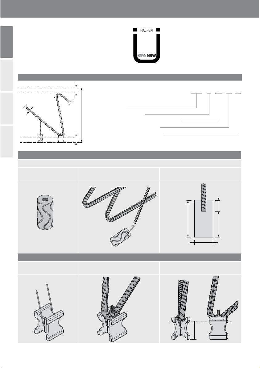
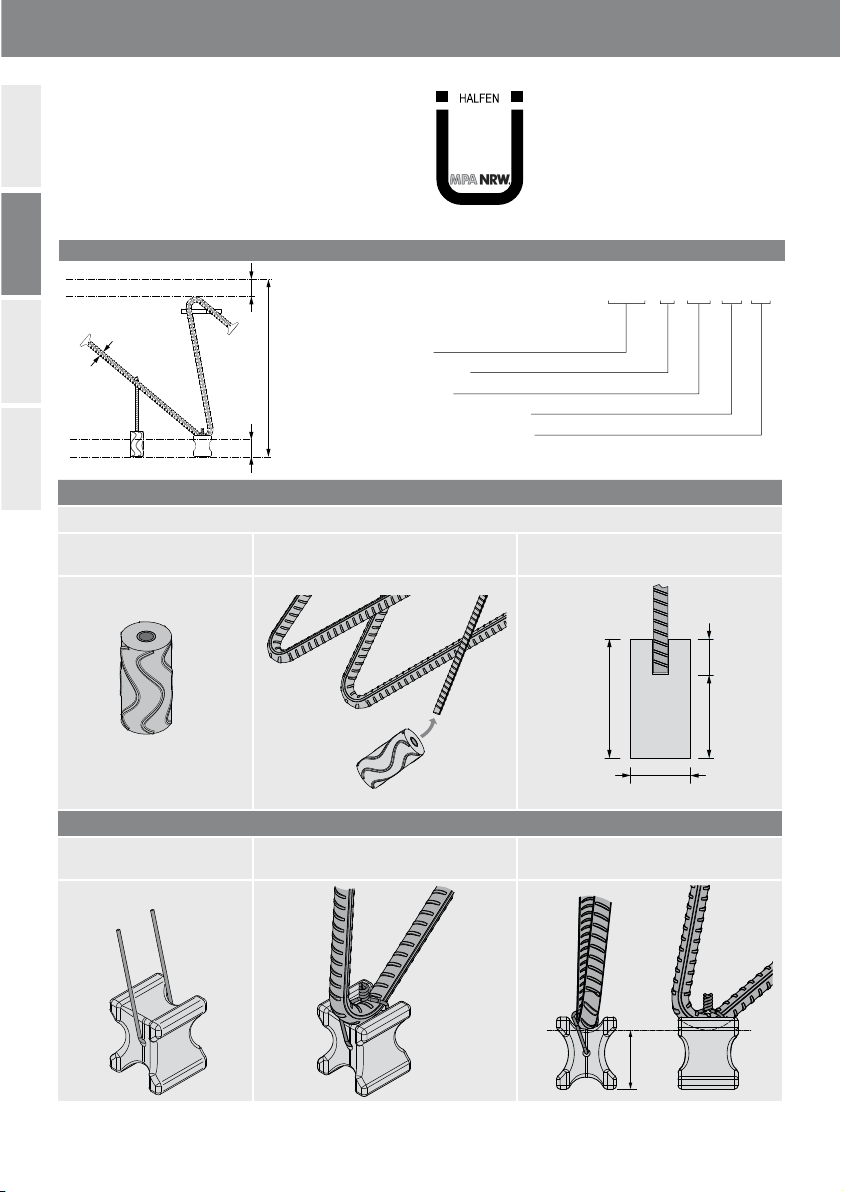
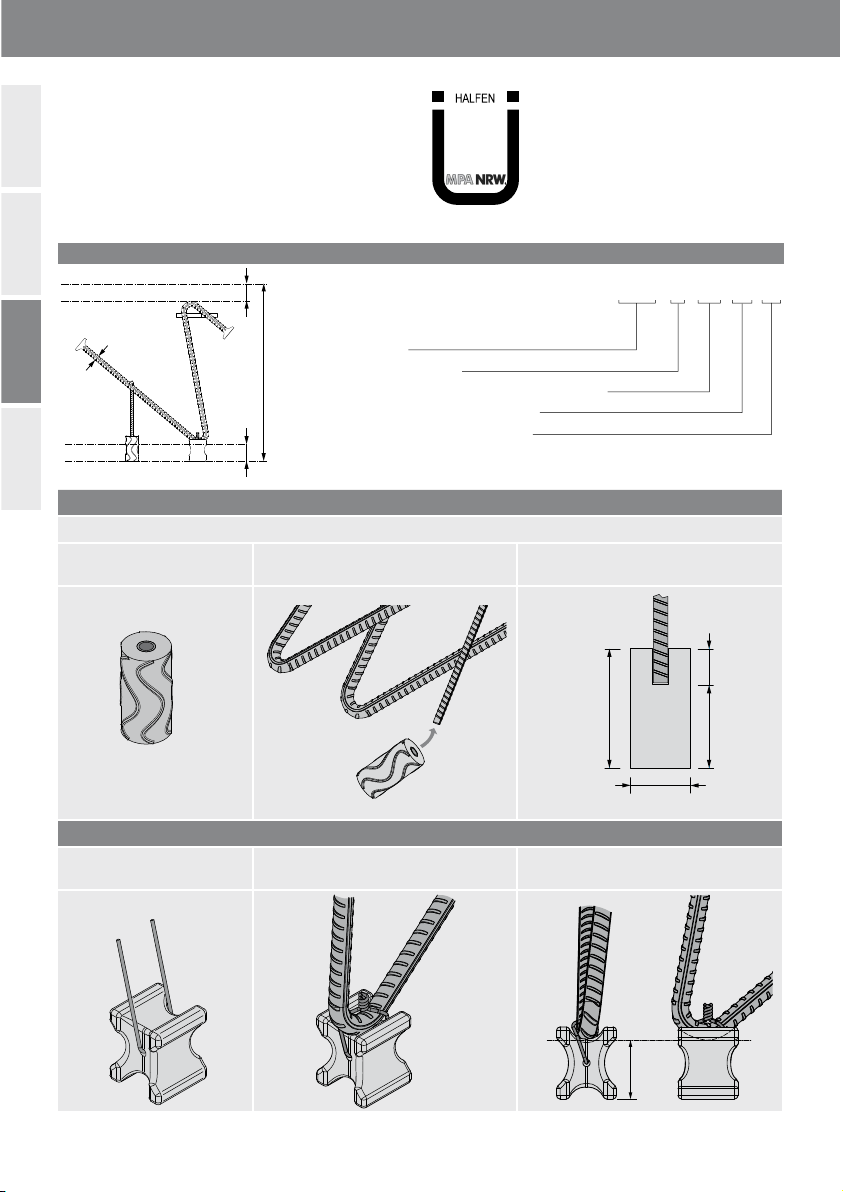
Column
0.3d 0.5d
d
h Fundation
cnom,u
cnom,o
Refer to the reinforcement plan for the
installation position for each element.
When placing the first row of HDB-Z elements,
the leading edge of the head bolt must be aligned
with the mark position for the column edge.
The second row must be placed with a
spacing of 0.5×d. As a rough guidance, the
bent bar of the second elements can be pushed
against the T-bar before precise placement.
Order of installation
1. Attach the spacers to the HDB-Z Elements
2. Install the bottom reinforcement layer — do not wire-tie!
3. Place the cross-layer of the bottom reinforcement loosely onto the first layer!
4. Install the HDB-Z Elements according to the reinforcement plan and the installation instructions.
5. Wire-tie the HDB-Z Elements and the previously installed reinforcement layers.
Finally, the remaining main longitudinal reinforcement is installed (upper reinforcement layer).
As before, ensure enough spacings to allow for installing and concreting to avoid conflict with the main
longitudinal reinforcement, and to ensure the concrete is properly compacted.
Correct position of the HDB-Z Elements Incorrect — elements too high Incorrect — elements too low
Do not install the HDB-Z Elements
on top of the reinforcement bars.
The T-bar should always be
perpendicular, and the clamping
plate should always be horizontal.
Make sure the main reinforcement can be
passed over and across the lower bend of
the HDB-Z Element on-site.

6© 2021 · INST_HDB-Z 01/21 · www.halfen.com
Deutsch EnglishFrançaisPolski
HALFEN HDB-Z Montageanleitung
Die HALFEN HDB-Z Bewehrungselemente
sind bauaufsichtlich zugelasssen, durch
das DIBt Berlin, als Durchstanzbewehrung
für Bodenplatten und Einzelfundamente.
Zulassung Nr.: Z-15.1-330
Zul.-Nr.
Z-15.1-330
DIBt
Bestellbeispiel: Maße in [mm] HDB-Z - 12 - 400 - 30 - 30
Typenbezeichnung
Ankerdurchmesser Ø (A)
Plattenhöhe hPlatte (E)
Betonüberdeckung oben cnom,o (C)
Betonüberdeckung unten cnom,u (D)
A
E
C
D
Kennzeichnung
Die gelieferten HALFEN HDB-Z Durchstanzelemente wur-
den nach den Angaben des Auftraggebers unter Beach-
tung der allgemeinen bauaufsichtlichen Zulassung Nr.
Z-15.1-330 hergestellt. Diese Montageanleitung gilt für
alle HDB-Z Typen. Die mitgelieferten Abstandhalter sind
zur Lagesicherung der HDB-Z Durchstanzbewehrung (wie
dargestellt) an der Unterseite der Biegungen bzw. an dem
Stützstab im hinteren Bereich zu befestigen.
Abstandhalter
Einfache Montage durch Aufstecken des Faserzementzylinder auf das Ende des T-Stücks.
Abstandhalter Aufstecken des Abstandhalters Endzustand vor dem Einbau der Elemente
Anbringen der vorderen Abstandshalter
Faserzementabstandhalter Anrödeln/Befestigen an den unteren Bie-
gungen
Endzustand vor dem Einbau der Elemente
Cnom,u
(Standard
50mm)
20
35
H
(Standard
70mm)
Cnom,u

7
© 2021 · INST_HDB-Z 01/21 · www.halfen.com
Deutsch EnglishFrançaisPolski
HALFEN HDB-Z Montageanleitung
Empfehlung: Hilfskonstruktion zum Einmessen
Eine Verwendung von HDB-Z mit unterschied-
lichem Durchmesser an einer Stütze ist nicht
zulässig!
Einbauhinweise
Der Messpunkt am
Bewehrungselement
befindet sich an der
vertikalen Tangente
des inneren Biegerol-
lendurchmessers.
Messpunkt/
Vertikale Tangente
Bei Transport und Verlegung der HDB-Z ist darauf zu achten, dass die Elemente nicht deformiert oder beschädigt werden. Bei
der Verlegung der HDB-Z sind die Vorgaben der Tragwerksplanung, insbesondere zur Längsbewehrung und zur Anordnung der
Bewehrungsstäbe zu berücksichtigen.
Die Position der Elemente ist dem Bewehrungsplan zu entnehmen. Abweichungen der Lage und der Abstände untereinander
im Grundriss der Platte gegenüber den Planungsunterlagen von mehr als einem Zehntel der Plattendicke sind nicht zulässig.
Zum Einmessen kann ein Monta-
geeisen auf die Klemmplatte und
an der hinteren Biegung angelegt
werden. Am Montageeisen kann
mit der Senkschnur oder der
Wasserwaage die genaue Positi-
on bestimmt werden. Wir emp-
fehlen eine Überprüfung auf bei-
den Seiten des HDB-Z Elements
vorzunehmen.
T-Stück
T-Stück
Cnom,u
Biegung
Klemmplatte
Element mit korrekt installierten Abstandhaltern –
fertig zur Installation auf der Sauberkeitsschicht Elemente nicht auf die Beweh-
rungsstäbe setzen! Das T-Stück
sollte immer lotrecht bzw. die
Klemmplatte immer horizontal
ausgerichtet werden.
Das Durchziehen der Längsbe-
wehrung durch die untere Bie-
gung muss bauseits gewährleistet
werden.
Von der Verwendung einer Mat-
tenbewehrung im Durchstanzbe-
reich wird abgeraten.
Zur Sicherstellung eines schnellen und fehlerfreien Einbaus beachten Sie die auf der Seite 9 vorgegebene
Arbeitsreihenfolge!
Kopfbolzen-
vorderkante
Der Einsatz der mitgelieferten Betonab-
standhalter wird dringend empfohlen.
Senklot oder Wasserwaage
Hilfsstab/Montageeisen
Bei der Ausrichtung der ersten Reihe der
HDB-Z Elemente muss die Kopfbolzenvor-
derkante in der Flucht der angezeichneten
Stützenkante liegen. Die zweite Elementrei-
he ist bei 0,5 × d anzusetzen. Zur Orientie-
rung kann das zweite Element vor dem ge-
nauen Einmessen mit dem gebogenen Stab
an das T-Stück gesetzt werden.

8© 2021 · INST_HDB-Z 01/21 · www.halfen.com
Deutsch EnglishFrançaisPolski
HALFEN HDB-Z Montageanleitung
Markieren der Stützen-
position...
... sowie der Verlege-
bereiche
Bodenplatte
geplante Stütze
ebener Untergrund
erste Reihe
folgende Reihe
Verlegen der ersten beiden Längsbewehrungslagen (Es sind die Angaben der Planungsunterlagen zu berücksichtigen)
Empfehlung: Verlege- und Rüttelgassen berücksichtigen um Kollisionen mit der Längsbewehrung zu vermeiden und um ein
ordnungsgemäßes Verdichten des Betons weiterhin zu gewährleisten. Längsbewehrung zuerst lose verlegen und erst nach
der Montage der HDB-Z Elemente mit den HDB-Z Elementen gemeinsam verrödeln!

9
© 2021 · INST_HDB-Z 01/21 · www.halfen.com
Deutsch EnglishFrançaisPolski
HALFEN HDB-Z Montageanleitung
HDB-Z Elemente in das erstellte Raster set-
zen (auf Betonabstandhalter achten) und
ggf. die Längsbewehrung ausrichten. Dabei
darauf achten, dass die unteren Biegungen
in einer Ebene mit der äußersten Beweh-
rungslage liegen.
Hinweis: zur Platzierung der Elemente sind
ggf. die Abstände der Längsbewehrungsstäbe
anzupassen. Dies ist in Absprache mit dem
Tragwerksplaner abzustimmen. Die Betonde-
ckung und die Anordnung ist den Planungs-
unterlagen zu entnehmen.
Der Einsatz der mitgelieferten Betonabstand-
halter wird dringend empfohlen. Von der Ver-
wendung einer Mattenbewehrung im Durch-
stanzbereich wird abgeraten.
Stütze
0,3d 0,5d
d
h Fundament
cnom,u
cnom,o
Die Position der Elemente ist dem Bewehrungs-
plan zu entnehmen.
Bei der Ausrichtung der ersten Reihe der HDB-Z
Elemente muss die Kopfbolzenvorderkante in der
Flucht der angezeichneten Stützenkante liegen.
Die zweite Elementreihe ist bei 0,5*d anzuset-
zen. Zur Orientierung kann das zweite Element
vor dem genauen Einmessen mit dem gebo-
genen Stab an das T-Stück gesetzt werden.
Arbeitsreihenfolge
1. Montage der Abstandshalter an den HDB-Z Elementen
2. Verlegung der untersten Bewehrungslage (nicht feströdeln!)
3. Die Kreuzlage der unterern Bewehrung nur lose darauflegen!
4. Platzierung der HDB-Z Elemente entsprechend der Verlege-Anordnung aus dem Bewehrungsplan
und unter Beachtung aller Montagehinweise
5. Befestigung der HDB-Z Elemente und der bereits verlegten Bewehrungslagen
Im letzten Schritt werden die restlichen Längsbewehrungen (obere Bewehrung) eingebaut. Hierzu sollten wie
zuvor Rüttel- und Verlegegassen vorgesehen werden.
Korrekte Lage der HDB-Z Bewehrung Unzulässig – Elemente zu hoch Unzulässig – Elemente zu tief
Elemente nicht auf die Beweh-
rungsstäbe setzen! Das T-Stück
sollte immer lotrecht bzw. die
Klemmplatte immer horizontal
ausgerichtet werden.
Das Durchziehen der Längsbewehrung
durch die untere Biegung muss bauseits
gewährleistet werden.

10 © 2021 · INST_HDB-Z 01/21 · www.halfen.com
Deutsch EnglishFrançaisPolski
HALFEN HDB-Z Notice d‘utilisation
Les armatures HALFEN HDB-Z sont
homologuées par le DIBt* Berlin comme
armatures de poinçonnement pour dalles
de fondation et dés de fondation.
Agrément n°Z-15.1-330.
Zul.-Nr.
Z-15.1-330
DIBt
A
E
C
D
Classification par type
Les armatures de poinçonnement HDB-Z sont fabriquées
conformément aux spécifications du client et à l’Agrément
Technique National (National Technical Approval)
n°Z-15.1-330.
Les présentes instructions s’appliquent à tous les types
d’armatures HDB-Z. Afin de garantir que l’armature de
poinçonnement HDB-Z reste bien en place, les distanceurs
fournis doivent être fixés sous le fer au niveau du cintrage
inférieur et à l’extrémité de l’armature en T arrière.
DIBt* = Deutsches Institut für Bautechnik.
(Institut allemand de la technologie de
construction)
Exemple de séquence : Dimensions [mm] HDB-Z - 12 - 400 - 30 - 30
Type de produit
Diamètre d’ancrage Ø (A)
Hauteur de semelle (dalle de fondation) hfooting (E)
Couche supérieure en béton Cnom,o (C)
Couche inférieure en béton Cnom,u (D)
Distanceurs
Installation simple : le distanceur fibrociment est inséré sur l’extrémité de l’armature de soutien arrière.
Distanceur Installation du distanceur Aperçu final avant installation des
armatures
Fitting the front spacers
Distanceur fibrociment Fixation au cintrage inférieur Aperçu final avant installation des
armatures
Cnom,u
(Standard
50mm)
20
35
H
(Standard
70mm)
Cnom,u

11
© 2021 · INST_HDB-Z 01/21 · www.halfen.com
Deutsch EnglishFrançaisPolski
HALFEN HDB-Z Notice d‘utilisation
Alignez les armatures HDB-Z en utilisant une section auxiliaire
de barre d’armature
Conformément à l’agrément Z-15.1-330, il est
interdit d’utiliser des armatures HDB-Z de
différents diamètres pour une même colonne !
Installation
Le point de mesure
est défini par la tan-
gente verticale au di-
amètre du rouleau
de cintrage.
Point de mesure/
tangente verticale
Pour faciliter l’alignement, une section
d’armature de renfort est placée sur
la plaque de fixation et appuyée
contre le cintrage arrière comme
illustré. La position correcte de
l’armature peut être contrôlée à l’aide
d’un fil à plomb. (voir illustration).
Nous recommandons d’effectuer ce
contrôle des deux côtés de l’armature
HDB-Z.
Armature de
soutien en T
Armature de
soutien en T
Cnom,u
Cintrage
Plaque de fixation
Armature avec distanceurs correctement installés — prête à être
installée sur une couche de fondation ou dans un coffrage N’installez pas les armatures de
poinçonnement HDB-Z sur les
armatures de renfort. L’armature
en T doit toujours être perpendi-
culaire et la plaque de fixation
toujours horizontale.
Assurez-vous que l’armature de
renfort longitudinale puisse
passer au-dessus et à travers le
cintrage inférieur de la zone de
poinçonnage sur site.
Nous déconseillons l’utilisation
de treillis d’armature dans la zone
de poinçonnement.
Pour une installation rapide et sans erreur, la séquence de pose présentée à la page 13 doit être suivie !
Bord en saillie
de la tête
d’ancrage
Il est vivement recommandé d’utiliser
les distanceurs fournis pour l’installation.
fil à plomb/ou niveau à bulle
Section auxiliaire
de barre
d’armature
Lors de la pose de la première rangée d’ar-
matures HDB-Z, le bord en saillie de la tête
d’ancrage doit être aligné avec le marquage
défini pour le bord de la colonne.
La seconde rangée doit être placée à 0,5
fois la valeur d.
Comme indication, la partie cintrée des se-
condes armatures peut être poussée contre
l’armature de soutien en T avant un place-
ment plus précis.
Lors du transport et de l’installation des armatures HDB-Z, veillez à éviter qu’elles ne soient endommagées ou déformées.
Les spécifications fournies par l’ingénieur de structures doivent toujours être suivies, en particulier celles concernant
l’armature de renfort principale et la disposition des armatures.
Reportez-vous au plan d’armature pour connaître la position d’installation de chaque élément. Les écarts par rapport
à la position et aux espacements spécifiés dans les plans entre les armatures dans la dalle (vue de dessus) et supérieurs
à 1/10 de l’épaisseur de la dalle ne sont pas autorisés.

12 © 2021 · INST_HDB-Z 01/21 · www.halfen.com
Deutsch EnglishFrançaisPolski
HALFEN HDB-Z Notice d‘utilisation
Marquage de la position
de la colonne...
... et des rangées
d’installation
Dalle de sol
emplacement
prévu de la
colonne
couche de fondation
ou coffrage
première
rangée
rangée suivante
Pose des deux premières rangées d’armatures de renfort longitudinales principales. Les spécifications fournies par
l’ingénieur de structures doivent être suivies.
Remarque : Prévoyez des espacements suffisants pour permettre l’installation et le coulage du béton, afin d’éviter tout pro-
blème avec l’armature de renfort principale et d’assurer un compactage correct du béton. Placez l’armature de renfort longitu-
dinale en premier sans la fixer, puis attachez-la aux armatures HDB-Z une fois que ces dernières ont été correctement installées.

13
© 2021 · INST_HDB-Z 01/21 · www.halfen.com
Deutsch EnglishFrançaisPolski
HALFEN HDB-Z Notice d‘utilisation
Placez les armatures HDB-Z sur les marquages (as-
surez-vous que les distanceurs soient correctement
installés), et réarrangez l’armature de renfort lon-
gitudinale si nécessaire. Assurez-vous que les cin-
trages inférieurs des armatures HDB-Z sont de ni-
veau avec les armatures de renfort les plus basses.
Remarque : il peut s’avérer nécessaire d’ajuster
l’espacement entre les armatures de renfort longi-
tudinales lors du placement des armatures HDB-Z.
Cela doit être discuté avec l’ingénieur de méca-
nique statique. Les positions des armatures et de
la couche en béton sont conformes aux spécifica-
tions des documents de planification. Nous re-
commandons d’utiliser les distanceurs pour béton
fournis. Nous déconseillons l’utilisation de treillis
d’armature dans la zone de poinçonnement.
Colonne
0.3d 0.5d
d
h Fondation
cnom,u
cnom,o
Reportez-vous au plan d’armature pour connaître
la position d’installation de chaque élément.
Lors de l’installation de la première rangée
d’armatures HDB-Z, le bord en saillie de la tête
d’ancrage doit être aligné avec le marquage défini
pour le bord de la colonne.
La seconde rangée doit être placée avec un es-
pacement de 0,5 fois la valeur d. Comme indica-
tion, la partie cintrée des secondes armatures peut
être poussée contre l’armature de soutien en T
avant un placement plus précis.
Ordre d’installation
1. Fixez les distanceurs aux armatures HDB-Z
2. Installez la rangée de renfort inférieure — ne la fixez pas !
3. Posez la rangée croisée de renfort inférieur sur la première rangée sans l’attacher !
4. Installez les armatures HDB-Z selon le plan d’armature et les instructions d’installation.
5. Fixez les armatures HDB-Z aux rangées d’armatures de renfort précédemment installées.
Pour terminer, l’armature de renfort longitudinale principale restante doit être installée (rangée de renfort
supérieure). Comme précédemment, ménagez suffisamment d’espacements pour permettre l’installation et
le coulage du béton, afin d’éviter tout problème avec l’armature de renfort longitudinale principale et
d’assurer un compactage correct du béton.
Correct position of the HDB-Z Elements Incorrect — elements too high Incorrect — elements too low
N’installez pas d’armatures HDB-Z
sur des armatures de renfort.
L’armature de soutien en T doit tou-
jours être perpendiculaire et la
plaque de fixation toujours horizontale.
Assurez-vous que l’armature de renfort princi-
pale puisse passer au-dessus et à travers le cin-
trage inférieur de l’armature HDB-Z sur site.

14 © 2021 · INST_HDB-Z 01/21 · www.halfen.com
Deutsch EnglishFrançaisPolski
HALFEN HDB-Z Instrukcja montażu
Elementy zbrojeniowe HALFEN HDB-Z są
dopuszczone do stosowania w budownict-
wie przez DIBt Berlin, jako zbrojenie na
przebicie dla płyt fundamentowych i stóp
fundamentowych. Aprobata techniczna nr
Z-15.1-330
Zul.-Nr.
Z-15.1-330
DIBt
Przykład: wymiary w [mm] HDB-Z - 12 - 400 - 30 - 30
Oznaczenie typu
Średnica pręta Ø (A)
Wysokość płyty fundamentowej hpłyta (E)
Otulina betonowa górą cnom,o (C)
Otulina betonowa dołem cnom,u (D)
A
E
C
D
Znakowanie
Dostarczone elementy na przebicie HALFEN HDB-Z
zostały wykonane według danych zamawiającego z
uwzględnieniem aprobaty technicznej nr Z-15.1-330.
Niniejsza instrukcja montażu obowiązuje dla wszystkich
typów HDB-Z. Dostarczone elementy dystansowe, do
zapewnienia właściwego położenia elementów HDB-Z
(jak na rysunku), mocowane są na dolnej stronie zagięć
prętów i na podpórce.
Element dystansowy
Montaż przez nasunięcie elementu dystansowego na końcówkę pręta podpórki.
Element dystansowy Nasunięcie elementu dystansowego Stan po zamontowaniu elementu
dystansowego
Przymocowanie przednich elementów dystansowych
Element dystansowy z
zaprawy cementowej
Przymocowanie drutem wiązałkowym do
dolnego łuku
Stan po zamocowaniu elementu
dystansowego
Cnom,u
(Standard
50mm)
20
35
H
(Standard
70mm)
Cnom,u

15
© 2021 · INST_HDB-Z 01/21 · www.halfen.com
Deutsch EnglishFrançaisPolski
HALFEN HDB-Z Instrukcja montażu
Zalecenie: konstrukcja pomocnicza do pomiaru
Zastosowanie elementów HDB-Z o różnych
średnicach przy jednym słupie jest niedopusz-
czalne!
Montaż
Punkt pomiarowy na
elemencie zbrojeni-
owym znajduje się
na pionowej stycznej
do średnicy rolki
gięcia
Punkt pomiarowy/
pionowa styczna
Przy transporcie i magazynowaniu elementów HDB-Z należy zwrócić uwagę, aby elementy nie uległy deformacji lub nie
zostały uszkodzone. Przy rozkładaniu elementów HDB-Z należy uwzględnić wytyczne projektu wykonawczego, w
szczególności odnoszące się do zbrojenia podłużnego i rozmieszczenia prętów zbrojeniowych.
Odchyłki położenia i odległości pomiędzy elementami w rzucie poziomym płyty w stosunku do dokumentacji o więcej niż
1/10 grubości płyty są niedopuszczalne.
Do pomiaru można wykorzystać
pręt oparty na płytce zaciskowej
przy łukach prętów. Przy pomocy
pionu lub poziomicy można
określić dokładne położenie.
Zaleca się sprawdzenie po obu
stronach elementu HDB-Z.
Podpórka
Podpórka
Cnom,u
Łuk zagięcia
Płytka zaciskowa
Właściwie zamocowane elementy dystansowe –
zestaw gotowy do montażu na warstwie wyrównawczej Nie opierać elementów na
prętach zbrojeniowych!
Po montażu podpórka powinna
być w pionie i płytka zaciskowa
w poziomie.
Należy zagwarantować
przewlekanie zbrojenia
podłużnego przez dolne
zbrojenie.
Odradza się stosowanie mat
zbrojeniowych w obszarze zbroje-
nia na przebicie.
Dla zapewnienia szybkiego i bezbłędnego montażu proszę zwracać uwagę na kolejność robót!
Czoło głowicy
Zaleca się zastosowanie dostarczonych
elementów dystansowych.
Pion lub poziomica
Pręt pomocniczy
Przy ustawianiu pierwszego rzędu
elementów HDB-Z czoło górnej głowicy
pręta musi pokrywać się w pionie z
krawędzią słupa. Drugi rząd elementów
należy umieścić w odległości 0,5*d.
W przybliżeniu można przed dokładnym
rozmierzeniem dosunąć drugi element do
podpórki T.

16 © 2021 · INST_HDB-Z 01/21 · www.halfen.com
Deutsch EnglishFrançaisPolski
HALFEN HDB-Z Instrukcja montażu
Oznaczenie lokalizacji
słupa…
…oraz obszarów
ułożenia
płyta fundamentowa
planowany słup
wyrównane podłoże
pierwszy rząd
kolejny rząd
Ułożenie pierwszych warstw zbrojenia podłużnego (należy uwzględnić dane projektu wykonawczego)
Zalecenie: w celu uniknięcia kolizji ze zbrojeniem podłużnym oraz dla zapewnienia właściwego zagęszczenia betonu,
należy uwzględniać wyznaczone pasy. Zbrojenie podłużne rozłożyć najpierw luźno i dopiero po montażu elementów
HDB-Z razem powiązać.

17
© 2021 · INST_HDB-Z 01/21 · www.halfen.com
Deutsch EnglishFrançaisPolski
HALFEN HDB-Z Instrukcja montażu
Elementy HDB-Z osadzić w przygotowany
raster (uważać na dystanse) i ewentualnie
wyregulować zbrojenie podłużne. Przy czym
zwracać uwagę, aby dolne łuki prętów leżały
w jednej płaszczyźnie z najniższą warstwą
zbrojenia.
Wskazówka: do umieszczenia elementów
należy dopasować odległości prętów
zbrojenia podłużnego. Należy uzgodnić to z
projektantem konstrukcji. Grubość otuliny
betonowej i rozmieszczenie należy odczytać
z projektu wykonawczego. Zaleca się
stosowanie dostarczonych elementów
dystansowych. Nie jest zalecane stosowanie
mat zbrojeniowych w obszarze przebicia.
Stütze
0,3d 0,5d
d
h Fundament
cnom,u
cnom,o
Położenie elementów należy odczytać z projektu
wykonawczego.
Przy ustawianiu pierwszego rzędu elementów
HDB-Z czoło górnej głowicy pręta musi
pokrywać się w pionie z krawędzią słupa.
Drugi rząd elementów należy umieścić w
odległości 0,5*d. W przybliżeniu można przed
dokładnym rozmierzeniem dosunąć drugi ele-
ment do podpórki T.
Kolejność montażu
1. Montaż dystansów na elementach HDB-Z
2. Rozłożenie najniżej leżącej warstwy prętów (nie wiązać!)
3. Warstwa krzyżująca się dolnego zbrojenia luźno rozłożyć!
4. Lokalizacja elementów HDB-Z odpowiednio do projektu wykonawczego z uwzględnieniem wszystkich
wskazówek montażowych.
5. Zamocowanie elementów HDB-Z i rozłożonych warstw zbrojenia.
W ostatnim kroku montowane jest pozostałe zbrojenie podłużne (zbrojenie górne). W tym celu tak jak
poprzednio należy zapewnić obszary do zagęszczenia i ułożenia.
Właściwe położenie zbrojenia HDB-Z Niedopuszczalne – elementy za
wysoko
Niedopuszczalne – elementy za
nisko
Nie opierać elementów HDB-Z na
prętach zbrojeniowych!
Po montażu podpórka powinna
być w pionie i płytka zaciskowa
w poziomie.
Należy zagwarantować przewlekanie
zbrojenia podłużnego przez dolne
zbrojenie.

18 © 2021 · INST_HDB-Z 01/21 · www.halfen.com

For more information on the products featured here, please contact Leviat:
Notes regarding this document
© Protected by copyright. The information in this publication is based on state-of-the-art technology
at the time of publication. In every case, project working details should be entrusted to appropriately
qualified and experienced persons. Leviat shall not accept liability for the accuracy of the information
in this document or for any printing errors. We reserve the right to make technical and design changes
at any time. With a policy of continuous product development, Leviat reserves the right to modify
product design and specification at any time.
Leviat.com
For information on certified management systems and standards, see www.halfen.com
Australia
Leviat
98 Kurrajong Avenue,
Mount Druitt, Sydney, NSW 2770
Tel: +61 - 2 8808 3100
Email: info[email protected]
Austria
Leviat
Leonard-Bernstein-Str. 10
Saturn Tower, 1220 Wien
Tel: +43 - 1 - 259 6770
Email: info.at@leviat.com
Belgium
Leviat
Borkelstraat 131
2900 Schoten
Tel: +32 - 3 - 658 07 20
Email: info[email protected]
China
Leviat
Room 601 Tower D,
Vantone Centre
No. A6 Chao Yang Men Wai Street
Chaoyang District
Beijing · P.R. China 100020
Tel: +86 - 10 5907 3200
Email: info.cn@leviat.com
Czech Republic
Leviat
Business Center Šafránkova
Šafránkova 1238/1
155 00 Praha 5
Tel: +420 - 311 - 690 060
Email: info.cz@leviat.com
Finland
Leviat
Vädursgatan 5
412 50 Göteborg / Sweden
Tel: +358 (0)10 6338781
Email: info[email protected]
France
Leviat
18, rue Goubet
75019 Paris
Tel: +33 - 1 - 44 52 31 00
Email: info[email protected]
Germany
Leviat
Liebigstrasse 14
40764 Langenfeld
Tel: +49 - 2173 - 970 - 0
Email: info.de@leviat.com
India
Leviat
309, 3rd Floor, Orion Business Park
Ghodbunder Road, Kapurbawdi,
Thane West, Thane,
Maharashtra 400607
Tel: +91 - 22 2589 2032
Email: info[email protected]
Italy
Leviat
Via F.lli Bronzetti 28
24124 Bergamo
Tel: +39 - 035 - 0760711
Email: info[email protected]
Malaysia
Leviat
28 Jalan Anggerik Mokara 31/59
Kota Kemuning,
40460 Shah Alam Selangor
Tel: +603 - 5122 4182
Email: info.my@leviat.com
Netherlands
Leviat
Oostermaat 3
7623 CS Borne
Tel: +31 - 74 - 267 14 49
Email: info[email protected]
New Zealand
Leviat
2/19 Nuttall Drive, Hillsborough,
Christchurch 8022
Tel: +64 - 3 376 5205
Email: info[email protected]
Norway
Leviat
Vestre Svanholmen 5
4313 Sandnes
Tel: +47 - 51 82 34 00
Email: info[email protected]
Philippines
Leviat
2933 Regus, Joy Nostalg,
ADB Avenue, Ortigas Center
Pasig City
Tel: +63 - 2 7957 6381
Poland
Leviat
Ul. Obornicka 287
60-691 Poznań
Tel: +48 - 61 - 622 14 14
Email: info[email protected]
Singapore
Leviat
14 Benoi Crescent
Singapore 629977
Tel: +65 - 6266 6802
Email: info[email protected]
Spain
Leviat
Polígono Industrial Santa Ana
c/ Ignacio Zuloaga, 20
28522 Rivas-Vaciamadrid
Tel: +34 - 91 632 18 40
Email: info.es@leviat.com
Sweden
Leviat
Vädursgatan 5
412 50 Göteborg
Tel: +46 - 31 - 98 58 00
Email: info[email protected]
Switzerland
Leviat
Hertistrasse 25
8304 Wallisellen
Tel: +41 - 44 - 849 78 78
Email: info.ch@leviat.com
United Kingdom
Leviat
A1/A2 Portland Close
Houghton Regis LU5 5AW
Tel: +44 - 1582 - 470 300
Email: info.uk@leviat.com
USA / Canada
Leviat
6467 S Falkenburg Rd.
Riverview, FL 33578
Tel: (800) 423-9140
Email: info[email protected]
For countries not listed
Email: info@leviat.com
Halfen.com

Imagine. Model. Make. Leviat.com
© 2021 U-116 – 01/21 PDF 07/21
Table of contents
Languages:
Other CRH Industrial Equipment manuals

CRH
CRH Leviat HALFEN DETAN-S User manual

CRH
CRH Leviat HALFEN MBT User manual

CRH
CRH Leviat HALFEN DEHA HA-N User manual

CRH
CRH Leviat HALFEN DEHA 6003 User manual

CRH
CRH Leviat HALFEN HBB User manual

CRH
CRH CRL SS96 User manual

CRH
CRH Leviat Halfen HCC User manual

CRH
CRH Leviat HALFEN HEK3 User manual

CRH
CRH Leviat HALFEN PSA User manual

CRH
CRH Leviat Ancon 2000 User manual