Nordco CGS User manual

APPENDIX A
CGS HAMMER
RAIL GAGER
Operation and
Maintenance
Manual
Applies to S/N 480025 and Above
Last Revision: Rev. -
JUNE 2007

This manual is a guide for the operation and routine maintenance of a NORDCO Railroad Maintenance
Machine. It covers product technical information, basic operating and maintenance procedures, and
safety information and is provided for use by the qualified personnel who will supervise, operate or service
the equipment described herein.
Measurements in this manual are given in both metric and customary U.S. unit equivalents.
Personnel responsible for the operation and maintenance of this equipment should thoroughly study the
manual before commencing operation or maintenance procedures.
This manual should be considered a permanent part of your machine and should
remain with the machine at all times.
Additional copies of this manual are available either as a part (Operation Manual
only) or a whole (operation and parts manual), at a nominal cost, through our Part
Sales Department. Additional service information, parts, and application information
is available through these Nordco product support resources:
NORDCO Sales: Milwaukee, Wisconsin
(414) 766-2180
NORDCO Parts: Milwaukee, Wisconsin
1-800-647-1724
Oshawa, Ontario, Canada
(905) 579-4058, Ext. 224
NORDCO Service: 1-800-445-9258
We ask that if you have any comments or suggestions about this manual, let us hear from you. We are
here to be of service to you, our customers. Direct your comments and inquiries to:
Technical Documentation Department
NORDCO Inc.
245 W. Forest Hill Avenue
Oak Creek, WI 53154

HAZARDOUS MATERIAL DATA
In an effort to provide information necessary for your employee safety training program and to meet the
requirements of OSHA Hazard Communication Standard 1910.1200, we have OSHA Form 20 Safety Data
Sheets available that cover the material contained in this machine.
If you are interested in receiving this information, please refer to the Name, model, and Serial Number of
your machine when calling or writing, and direct your inquiries to:
Vice-President of Operations
NORDCO Inc.
245 W. Forest Hill Avenue
Oak Creek, WI 53154
Fax: (414) 766-2299
Phone: (414) 766-2288

Curve Gang Hammer Model A APPENDIX A
JUNE/2007 (4945-4800) Safety, Page 1
SAFETY
GENERAL
These safety instructions are in addition to those
listed in the SAFETY section of CGS Machine
manuals. These instructions only apply to the use of
the Rail Gager. It is important that you understand
ALL of the safety instructions before you operate this
piece of optional equipment. Learn how to operate
the Rail Gager and how to use controls properly.
DO NOT use this option for work operations other
than for which it was intended.
NORDCO is not responsible for any modifications
made without authorization or written approval.
Replace all NORDCO and OEM parts with genuine
NORDCO or OEM parts. Use of non-OEM parts
could compromise the safety of your machine.
FRA regulations require that a copy of this Operation
Manual be kept on the machine at all times.
Additional copies of the Operation Manual only can be
ordered from Nordco Parts Sales at 1-800-647-1724.
FOLLOW SAFETY INSTRUCTIONS
Carefully read all safety messages in this manual.
Learn how to operate the machine and how to use
controls properly. Do not let anyone operate this
machine without instruction. Failure to understand the
contents of this manual could result in serious
personal injury or death.
SAFETY ALERT SYMBOLS!
These are the safety-alert symbols. These
symbols means pay attention! Your safety is
at risk!
DANGER is used to indicate a definite hazardous
situation which, if not avoided, WILL result in severe
bodily harm or even death.
WARNING indicates a potentially hazardous situation
which, if not avoided, COULD result in severe bodily
harm or even death.
CAUTION indicates a potentially hazardous situation
which, if not avoided, MAY result in minor or
moderate injury.
CAUTION without the safety “!” means that failure to
follow the alert may result in machine damage.
SAFETY means that the following points are
instructions for safely operating the machine or the
specific component of the machine.
Please read and comply with all of the safety
precautions in both the CGS Machine Manual and
this optional equipment manual.

APPENDIX A Curve Gang Hammer Model A
Safety, Page 2 JUNE/2007 (4945-4800)
GENERAL SAFETY TIPS
Only trained and authorized personnel familiar with
the function of a gaging machine should be allowed to
operate this machine. In addition, all personnel at the
worksite (gang) should be aware of the safety
concerns and their individual responsibilities prior to
working this machine.
•Review the operating instructions if you are
unsure of anything.
•Use the “Pre-operational Checklist” to check the
machine for obvious faults. Repair or replace as
necessary PRIOR to operating the machine.
•Before climbing onto the machine, make certain
the area around and under the machine is clear of
obstructions and personnel.
•Never climb on to, or off of, the machine while it is
in motion.
•There are lockups on this machine that are used
for both work and travel. These should be kept
clear and free of debris, grease, etc. See
Lockup section for instructions on their use.
•Inspect safety decals and replace when they
become unreadable or are damaged. (See
“Safety Decals”at the end of this Safety section).
•Use the “STARTUP Checklist” to check the
machine controls and gauges to make certain all
systems are operating correctly.
•Press the EMERGENCY STOP pushbutton on
the center control console in emergencies and
potentially dangerous situations.
•If personnel or bystanders are near the machine
during operation, give a warning signal using the
air horn. If they fail to respond to this warning,
stop operation immediately.
•When leaving a machine engine running, make
certain that the parking brake is applied and the
electrical interlock button has been activated.
SAFETY DURING MAINTENANCE
The following guidelines are suggested when
performing maintenance:
1. Always chock the wheels
2. Alert others in the area that service or
maintenance is being performed on this
machine.
3. Become familiar with, and use, your
company’s lockout/tagout procedures when
performing maintenance on this machine.
See LOCKOUT/TAGOUT REQUIREMENTS
later in this Safety Section for a chart on
energy sources located on this machine.
4. Do not start the engine if repairs or work is
being performed alone. You should always
have at least two people working together if
the engine must be run during service. One
person needs to remain in the command
position (at the controls), ready to stop the
machine and shut off engine if the need
arises.
5. Collect oils and fuels and dispose of them
properly. There is a danger of scalding when
working with engine oils.
6. Use only Nordco supplied repair parts for this
machine. Use of non-OEM designed parts
could comprise the integrity of this machine.
7. There are welding cautions on this machine.
Pay attention to them PRIOR to welding.
8. Kits supplied by Nordco have welding
instructions included. Welding of any
components NOT of Nordco’s manufacture or
failure to follow these instructions may affect
the stability of this machine.

Curve Gang Hammer Model A APPENDIX A
JUNE/2007 (4945-4800) Safety, Page 3
CGS RAIL GAGER
SAFETY ALERTS
Failure to engage all lockup devices before propelling at travel speed can result in injury to
personnel and/or extensive damage to the machine.
Always turn off machine when performing maintenance, making adjustments, or whenever
unintended movement of machine could occur; unless directed otherwise. Failure to
comply could result in personal injury and/or damage to the machine.
Do not attempt to operate or adjust the Rail Gager without first learning how to operate the
spiking machine.

APPENDIX A Curve Gang Hammer Model A
Before Operation, Page 4 JUNE/2007 (4945-4800)
BEFORE OPERATION
Do not attempt to operate or adjust the Rail Gager
without first learning how to operate the spiking
machine.
It is always a good practice to become familiar with the components of
the machine you are using.
GENERAL
To better understand the function of the CGS Gager, you have to
understand the concept of bringing a rail “to gage”.
Track gage is the distance between rail heads. See Figure 1. Standard
track gage is 56-1/2" but gage may vary at crossings, switches and
curves.
The process of adjusting the distance between rail ball heads is called
gaging. The rail gager on the CGS Machine accomplishes this in two
basic steps:
1. An LVDT inside the Gager Buggy measures the actual distance
between rail heads and relays this information electronically to
the Programmable Logic Controller (PLC) inside the Operator
Control Box and to a meter located in front of the Spike Driver
Operator.
2. After the gage distance signal is received at the PLC, signals are
sent to the solenoid valves that control the rail gage assembly.
See Figure 3. The rail clamp, positioned over the fixed rail,
closes. Next, the pregager cylinder/lever pushes the rail and the
tie plates slightly under gage. The gager cylinder then pushes
the free rail and tie plates out until the rail reaches the gage
position selected at the gager meter by the operator, after which
spikes can be driven.
The CGS Rail Gager consists of two assemblies, both of which MUST be
locked up for travel (See Lockups later in this manual):
Curve Gang Hammer Model A APPENDIX A
JUNE/2007 (4945-4800) Before Operation, Page 5
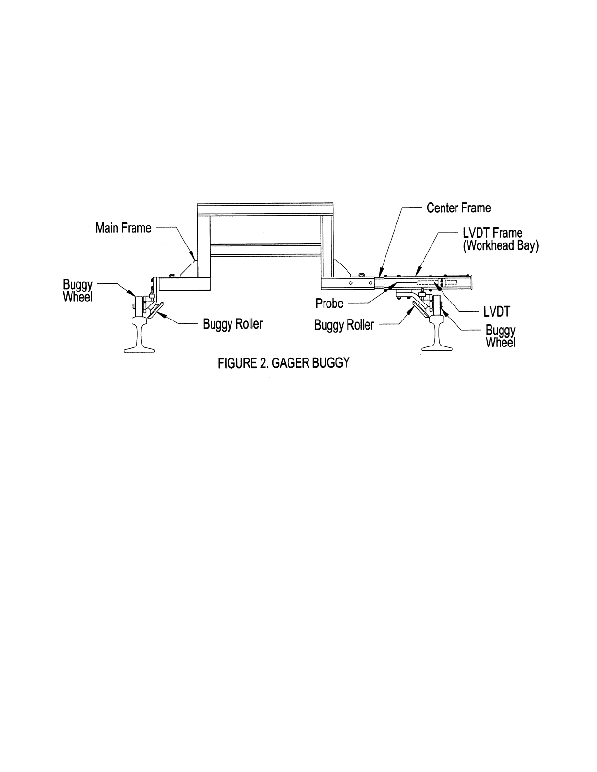
GAGER BUGGY
The gager buggy consists of a three piece tubular frame with a roller
assembly mounted to each end. These roller assemblies allow the buggy
to ride the rail continuously during gaging operations. The LVDT frame
houses the LVDT position sensor.
The Gager Buggy LVDT monitors the position of the free rail, and sends a
signal back to the PLC and electronic meter.

APPENDIX A Curve Gang Hammer Model A
Before Operation, Page 6 JUNE/2007 (4945-4800)
GAGER ASSEMBLY
The gager assembly consists of a free floating frame, a rail clamp
assembly, a pregaging lever and cylinder, a gaging cylinder, and two
roller assemblies. The gager frame is supported by a cylinder which not
only raises and lowers the assembly, but includes the lockup feature of
the gager. A pair of rollers is attached to the gager frame to allow the
gager to ride on top of the rail. The position of these rollers is adjustable
to accommodate various rail sizes.
The gager assembly is designed to apply the necessary force to the free
rail to position it at the proper gage distance from the fixed rail prior to
spiking operations.
Curve Gang Hammer Model A APPENDIX A
JUNE/2007 (4945-4800) Before Operation, Page 7
INSTRUMENTS AND CONTROLS
The gager meter box and portions of the Main Control Panel control the gager assembly in its entirety. An “At-Gage”
light in front of the Spike Driver Operator will illuminate when the rail has reached gage, and is the signal for the
operator to begin spiking.
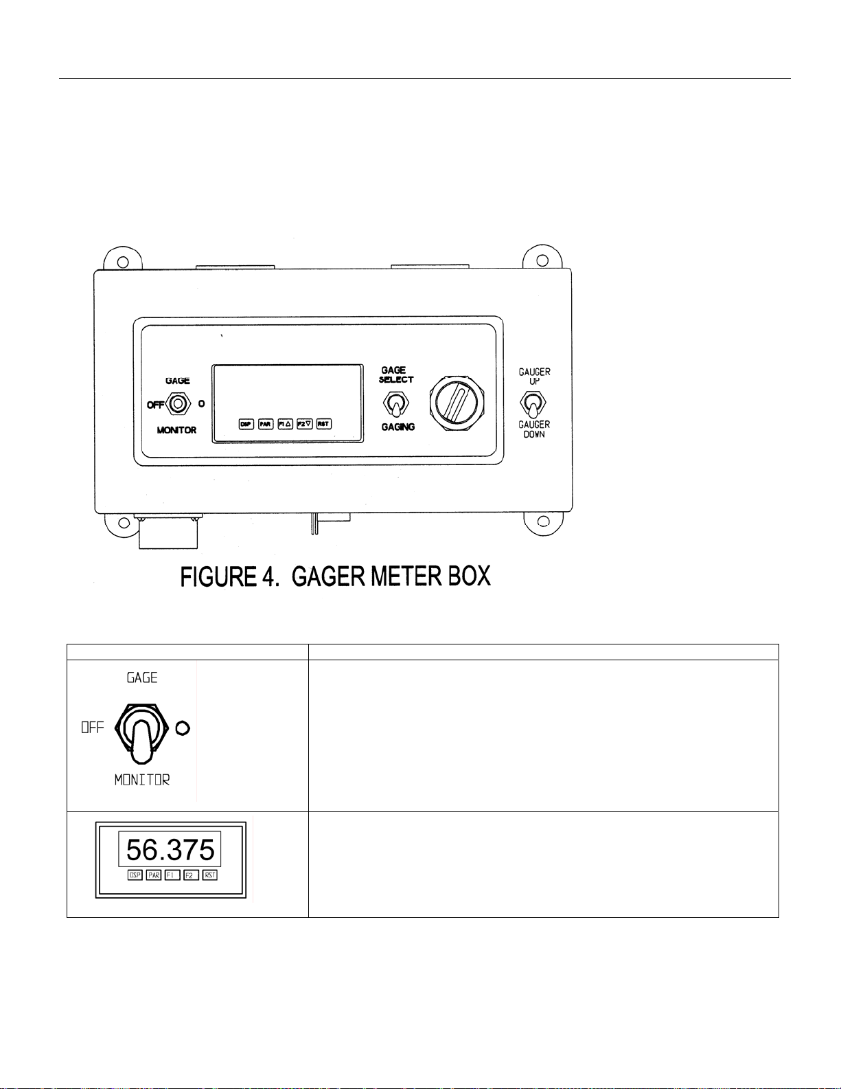
GAGER METER BOX
CONTROL OR INSTRUMENT FUNCTION
This is a 3-position switch that controls the electrical components of the
gager. The switch positions and their functions are as follows:
Gage: Turns the gager electronic system ON. Readout meter will light up
and remain on until this switch is turned to the OFF position.
OFF: Turns the gager electronic system OFF.
MONITOR: Used to monitor the rail gage WITHOUT the use of the gager.
Readout meter will remain on until switch is manually returned to center.
READOUT METER: Indicates rail gage. Meter scale is digital and reads to
the thousandths of an inch. This meter has been pre-programmed prior to
sale. Instructions for reprogramming in the event of catastrophic failure are
included in the maintenance section of this appendix.
The buttons at the bottom of the readout meter are used for reprogramming
the meter.

APPENDIX A Curve Gang Hammer Model A
Before Operation, Page 8 JUNE/2007 (4945-4800)
CONTROL OR INSTRUMENT FUNCTION
This is a two position switch that controls the work operations of the gager
itself.
SELECT: Activates the potentiometer allowing you to set the gage. The
digital meter will read the potentiometer position.
GAGING: The digital meter will read the actual rail gage (LVDT position).
Gager SELECT Potentiometer:
The gage select switch must be in the SELECT mode before the
potentiometer functions. This is used by the operator to change the
desired gage for varying track conditions such as crossings, switches,
steep curves, etc.
Gager UP/DOWN Control Switch:
This is a two position switch that activates and deactivates the rail gaging
process. Immediate action of the gager assembly is dependent on the rail
type mode selected (JOINTED or WELDED) on the Main Control Panel.
GAGER UP: Deactivates the gaging process, and raises the rail gager
assembly to the stored/lockup position.
GAGER DOWN: Activates the gaging process based on the position of
JOINTED or WELDED switch:
If the rail type mode is WELDED, the rail gager assembly is immediately
lowered to the rail.
If the rail type mode is JOINTED, the gager assembly will not lower onto
the rails until the SET button on either hand controller has been pressed.

Curve Gang Hammer Model A APPENDIX A
JUNE/2007 (4945-4800) Before Operation, Page 9
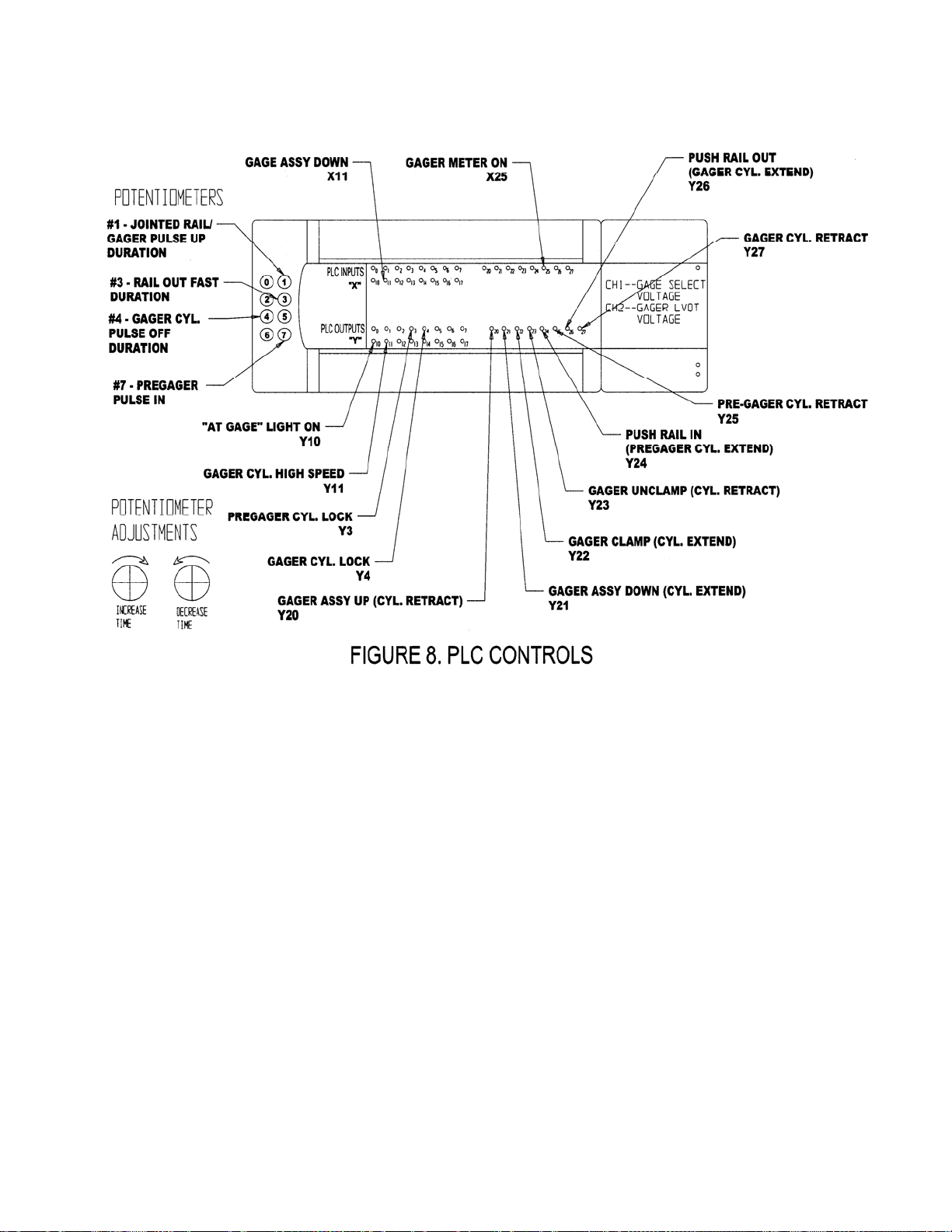
GAGER-RELATED ITEMS IN THE OPERATOR CONTROL BOX
The following figures represent gager controls that are housed in the operator control box. These are for reference
only. Refer to the Electrical Section of the CGS manual for details and most current drawings of these controls.

APPENDIX A Curve Gang Hammer Model A
Before Operation, Page 10 JUNE/2007 (4945-4800)

Curve Gang Hammer Model A APPENDIX A
JUNE/2007 (4945-4800) Before Operation, Page 11
APPENDIX A Curve Gang Hammer Model A
Before Operation, Page 12 JUNE/2007 (4945-4800)
Curve Gang Hammer Model A APPENDIX A
JUNE/2007 (4945-4800) Before Operation, Page 13
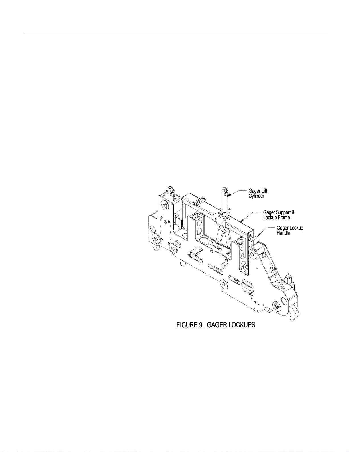
LOCKUPS
Certain machine components have lock-up features for use during high-
speed travel, towing, or during machine storage.
Failure to engage all lockup devices before propelling at
travel speed can result in injury to personnel and/or
extensive damage to the machine.
RAIL GAGER
The rail gager assembly is equipped with a single lockup pin. See
Figure 9. The rail gager must be in the fully raised and stored position
before the lockup pin can be inserted. This can be accomplished by
either switching the Gager UP/DOWN toggle switch to the UP position
or switching the WORK/TRAVEL toggle switch to the TRAVEL mode.
APPENDIX A Curve Gang Hammer Model A
Before Operation, Page 14 JUNE/2007 (4945-4800)
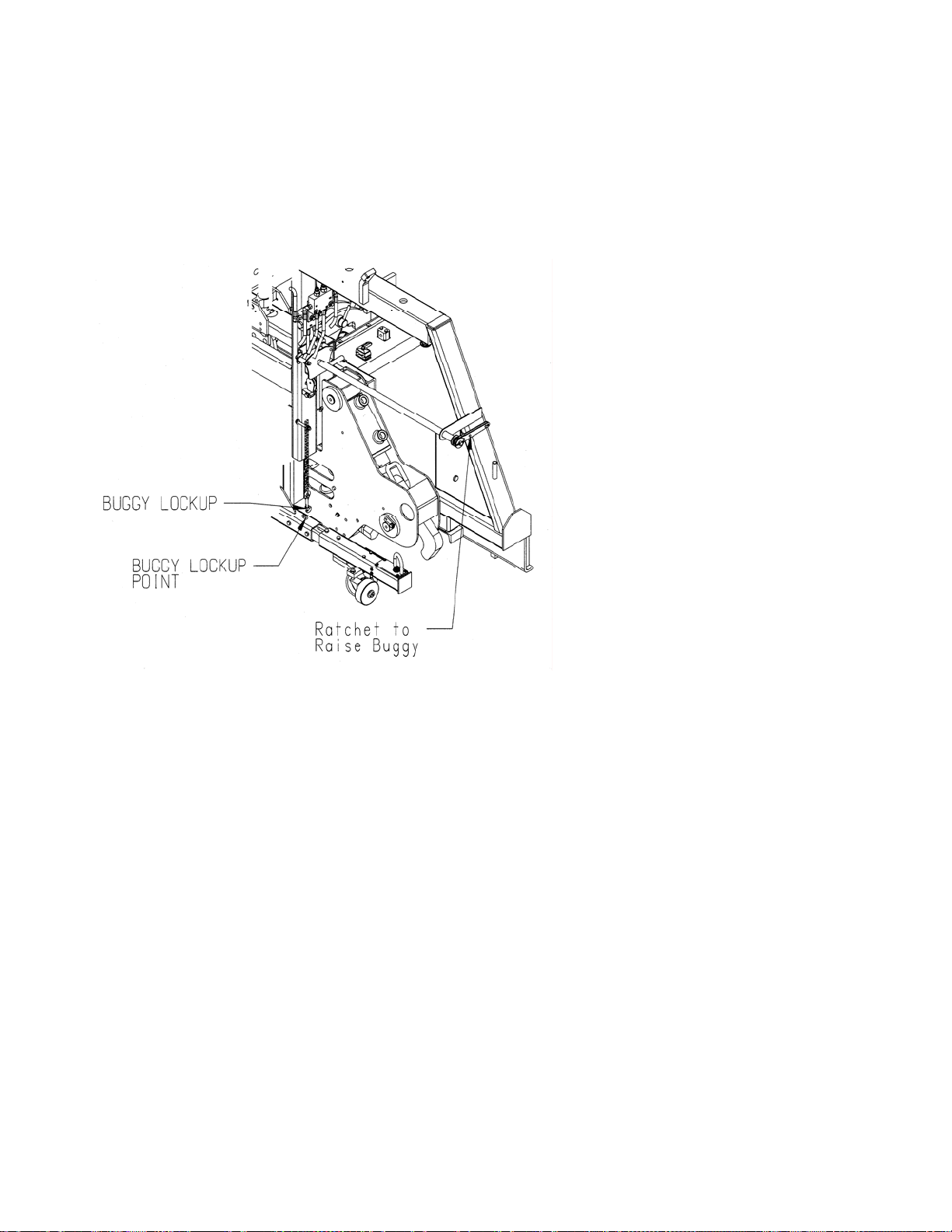
ROLLER BUGGY
The Roller Buggy is locked up on both the left frame and right frame by a
chain/hook assembly. The buggy must be raised off the rail to a point
the chain/hook will easily attach to the eyes on the frame.
To lower the buggy, turn the crank handle counter clockwise, to raise the
buggy turn the crank handle clockwise.
FIGURE 10. GAGER BUGGY LOCKUPS

Curve Gang Hammer Model A APPENDIX A
JUNE/2007 (49454800) Setup, Page 15
GAGER SETUP/ADJUSTMENTS
Prior to using the gager on any track conditions, the adjustment and
alibration procedures given in this section must be performed.c
Always turn off machine when performing maintenance,
making adjustments, or whenever unintended movement of
machine could occur; unless directed otherwise. Failure to
comply could result in personal injury and/or damage to the
machine.
ROLLER BUGGY WHEEL HEIGHT ADJUSTMENT
The Roller Buggy must ride on the rails so that each buggy guide
roller rides against the inside of the both rails at the correct height.
To adjust the Roller Buggy height proceed as follows:
1. Lower Roller Buggy to track with enough slack in cable to
allow the weight of the buggy to rest on rail.
2. Make certain that the buggy guide roller on the main frame
is on the inside of the rail.
3. Push on end of LVDT frame until buggy guide roller snaps onto
the inside of rail.
4. Locate locknut and adjustment screw as shown in Figure 12.
Loosen nut. Note: LVDT Frame side is shown, main frame side
is opposite.

APPENDIX A Curve Gang Hammer Model A
Before Operation, Page 16 JUNE/2007 (49454800)
5. Turn adjustment screw until buggy guide roller is lowered to
a position 5/8" down from the top of the rail, or as shown in
Figure 13.
6. Tighten locknut.
7. Repeat steps 4 through 6 for the Main Frame (Left) Roller
Buggy guide roller.
Table of contents
Other Nordco Industrial Equipment manuals


