NORDICCO NORTHERN AIR AMPLIFY User manual

Vers. 1.0
INSTALLATION MANUAL
NORTHERN AIR®AMPLIFY
ENGLISH
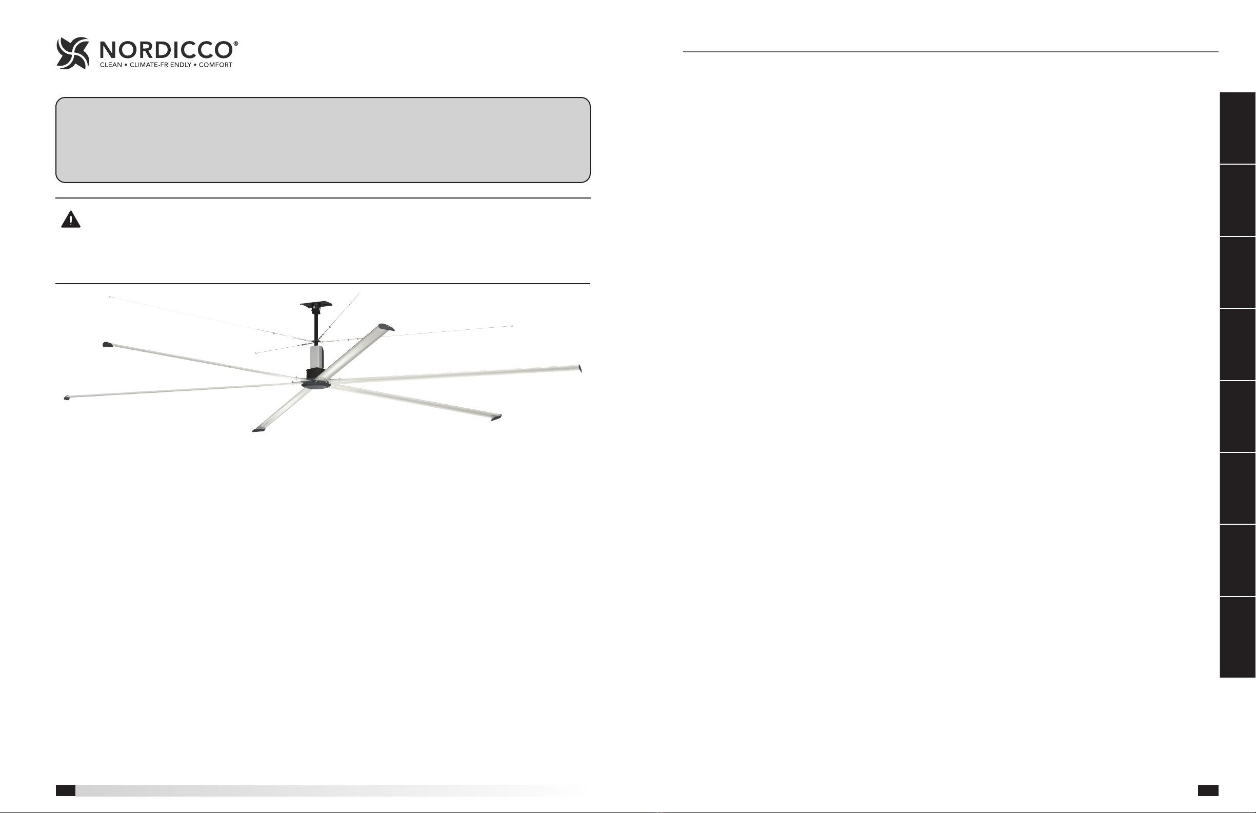
AMPLIFY Models are the ideal choice for providing year-round comfort in air circulation and destratification
applications. Featuring an aerodynamic, extruded aluminum airfoil design and a high efficiency direct drive motor,
Amplify delivers maximum airflow at a fraction of the operating cost of other HVLS fans. And, with its universal
ceiling mount, the Amplify fan is the easiest 6 m and 7,3 m HVLS fan to install in the market!
IMPORTANT: AMPLIFY fans must be installed with the supplied CAT communication cable or thru Northern
Sky. Cable must be twisted pair, shielded. CAT 5/6. Cable must use shielded RJ45 connectors with a soldered
drain. Individual CAT 5/6 cable lengths must not exceed 60 m in order to prevent network communication
issues.
Required Tools
The following tools will be required to complete the
installation of every Amplify fan. Additional tools may be
required depending on the application and installation
location of the fan.
• Socket Wrench and 17mm Sockets
• 11 m, 13 mm, 14 mm and 19 mm Wrenches
• Adjustable Wrench
• Torque Wrench (up to 70 Nm)
• Torque Wrench (up to 160 Nm)
• Drill and 19 mm Drill Bit
• Phillips Screwdriver
• Level
• Impact Driver
• #2 Phillips Bit and Driver
• 10 mm Magnetic Nut Driver
• Magnetic Nut Driver Extension
NOTE: Amplify fans components can weigh 41 kg or
greater depending upon the fan size and accessories
that are provided. A suitable means for lifting the weight
of the fan to the mounting point, such as a scissor lift,
should be used for all Amplify fan installations.
Quick Start Guide
Step 1 - Step 12 . . . . . . . . . . . . . . . . . . . . .
General Information
Required Tools
General Safety Information . . . . . . . . . . . . . . .
Receiving. . . . . . . . . . . . . . . . . . . . . . . . .
Unpacking . . . . . . . . . . . . . . . . . . . . . . . .
Storage. . . . . . . . . . . . . . . . . . . . . . . . . .
Inspection and Maintenance During Storage . . . . . .
Removing from Storage . . . . . . . . . . . . . . . . .
Fan Components. . . . . . . . . . . . . . . . . . . . .
Pre-Installation
Pre-Installation Checks. . . . . . . . . . . . . . . . . .
Minimum Spacing Requirements . . . . . . . . . . . .
Mechanical Installation
Mounting Installation . . . . . . . . . . . . . . . . . .
I-Beam Mounting . . . . . . . . . . . . . . . . . . .
Steel Truss Mounting . . . . . . . . . . . . . . . . .
Wood Beam Mounting . . . . . . . . . . . . . . . .
Motor/Hub to Downtube Installation . . . . . . . . . .
Safety Retention Cable Installation . . . . . . . . . . .
Standard Steel Cable Clamp . . . . . . . . . . . . .
Gripple® Hardware (Optional) . . . . . . . . . . . .
Guy Wire Installation. . . . . . . . . . . . . . . . . . .
Standard Steel Cable Clamp . . . . . . . . . . . . .
Gripple® Hardware (Optional) . . . . . . . . . . . .
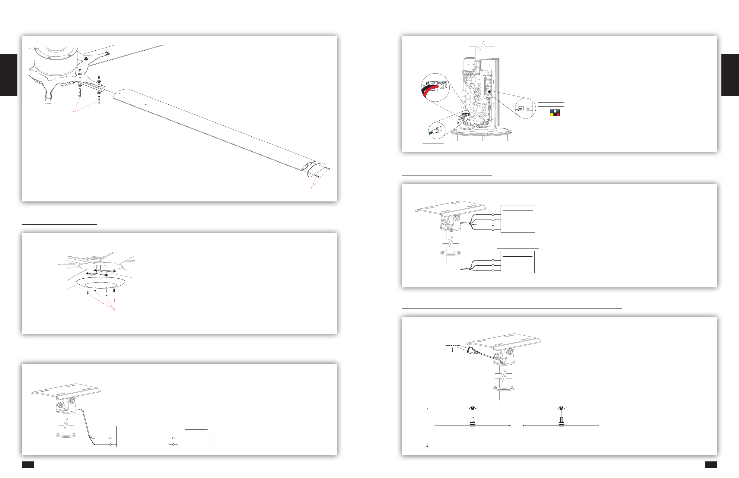
Airfoil Blade and Winglet Installation . . . . . . . . . .
Hub Plate Installation . . . . . . . . . . . . . . . . . .
Fire System Integration
Fire System Integration (Optional) . . . . . . . . . . .
Electrical Installation
Motor Cable Connection . . . . . . . . . . . . . . . .
Power Wiring. . . . . . . . . . . . . . . . . . . . . . .
With Optional Electrical Plug . . . . . . . . . . . . .
Without Optional Electrical Plug . . . . . . . . . . .
Disconnect and Fuse Installation . . . . . . . . . . . .
Communication Wiring . . . . . . . . . . . . . . . . .
With Pre-Built CAT-5/6 Cable . . . . . . . . . . . . .
Fan Networking
First Fan . . . . . . . . . . . . . . . . . . . . . . . . .
All Remaining Fans. . . . . . . . . . . . . . . . . . . .
Operation And Maintenance
Pre-Start-Up Checks . . . . . . . . . . . . . . . . . . .
Fan Operation . . . . . . . . . . . . . . . . . . . . . .
Fan Inspection . . . . . . . . . . . . . . . . . . . . . .
Fan Maintenance. . . . . . . . . . . . . . . . . . . . .
Table of Contents
Quick Start
Guide
General
Information Pre-Installation Mechanical
Installation
Fire System
Integration
Electrical
Installation
Fan
Networking
Operation And
Maintenance
3
22
NORTHERN AIR®AMPLIFY
Overhead Ceiling Fans
Installation, Operation and Maintenance Manual
Please read and save these instructions for future reference. Read carefully before attempting to assemble, install,
operate or maintain the product described. Protect yourself and others by observing all safety information. Failure
to comply with these instructions will result in voiding of the product warranty and may result in personal injury
and/or property damage.
Overhead Ceiling Fans

Quick Start Guide
REFER TO INSTALLATION MANUAL FOR COMPLETE INSTALLATION INSTRUCTIONS.
QUICK START GUIDE DOES NOT REPLACE INSTALLATION MANUAL INSTRUCTIONS.
STEEL BEAM
DOWNTUBE AND MOUNT ASSEMBLY
GRADE 8 NYLON LOCKNUT
WASHER
I-BEAM CLAMPING PLATE SHIM
I-BEAM CLAMPING PLATE
PROVIDED GRADE 8 BOLTS
UNIVERSAL MOUNTING PLATE
STEEL I-BEAM INSTALLATION
• GO TO SECTION MECHANICAL INSTALLATION
• FASTENER KIT
IMPORTANT: I-BEAM MUST HAVE MINIMUM 127 MM.
FLANGE WIDTH AND 13 MM. FLANGE THICKNESS
IMPORTANT: DO NOT INSTALL ON FABRICATED
I-BEAMS
STEP #1 - MOUNT INSTALLATION
DOWNTUBE AND MOUNT ASSEMBLY
13 MM GRADE 8 BOLT
WASHER
GRADE 8 NYLON LOCKNUT
13 MM GRADE 8 BOLT
(BY OTHERS)
13 MM GRADE 8
NYLON LOCKNUT
WASHER
SQUARE WASHER PLATE
STEEL TRUSS - BAR JOIST
STEEL TRUSS - BAR JOIST
STRUCTURAL STEEL ANGLES
(BY OTHERS)
STEEL TRUSS INSTALLATION
• GO TO SECTION MECHANICAL
INSTALLATION
• FASTENER KIT
IMPORTANT: TRUSSES MUST HAVE
MINIMUM 127 MM CHORD WIDTH
IMPORTANT: STEEL ANGLES MUST BE
MINIMUM OF 100 x 100 x 6,5 MM THICK
IMPORTANT: SPAN LENGTH MUST NOT
EXCEED 2,4 M.
GRADE 8 NYLON LOCKNUT
WASHER
DOWNTUBE AND MOUNT ASSEMBLY
13 MM GRADE 8 BOLT
WOOD BEAM
(BY OTHERS)
UNIVERSAL MOUNTING PLATE
WOOD BEAM BRACKET
13 MM GRADE 8 BOLT
(BY OTHERS)
WASHER
WOOD BEAM INSTALLATION
• GO TO SECTION MECHANICAL INSTALLATION
• FASTENER KIT
IMPORTANT: WOOD BEAM MUST BE 115 TO
225 MM WIDE
IMPORTANT: TORQUE ALL BOLTS TO 80 FT-LBF (108.5 N-m)
IMPORTANT: TORQUE ALL BOLTS TO 80 FT-LBF (108.5 N-m)
IMPORTANT: TORQUE ALL BOLTS TO 45 FT-LBF (61.0 N-m)
Quick Start
Guide
General
Information Pre-Installation Mechanical
Installation
Fire System
Integration
Electrical
Installation
Fan
Networking
Operation And
Maintenance Troubleshooting Reference
STEP #2 - MOTOR INSTALLATION
STEP #3 - SAFETY CABLE AND GUY WIRE INSTALLATION
10 MM GRADE 8 BOLT
1
2
1
POWER
GROUND
POWER
2
GROUND
M4 - 0.7 x 10 MACHINE SCREW
FRONT VFD COVER
DOWNTUBE AND MOUNT ASSEMBLY
3
HALL CONNECTION
NOTE:
HALL CABLE PLUG HAS
BUILT-IN ALIGNMENT TAB
DO NOT FORCE THIS PLUG
3HALL
CONNECTION
MOTOR INSTALLATION
• GO TO SECTION MECHANICAL
INSTALLATION
• FASTENER KIT
IMPORTANT: ELECTRICAL CABLES
FROM MOTOR MUST BE ON SAME
SIDE AS BLACK PLASTIC VFD COVER.
CABLES ARE NOT LONG ENOUGH
TO REACH CIRCUIT BOARD FROM
OPPOSITE SIDE. MOTOR MUST BE
REMOVED AND ROTATED 180° IF
INSTALLED INCORRECTLY.
TURNBUCKLE
CABLE CLAMP
GUY WIRE
QUICK LINK
EYEBOLT
BEAM CLAMP
ASSEMBLY
SAFETY CABLE
CABLE CLAMP
DOWNTUBE AND
MOUNT ASSEMBLY
DEAD END
LIVE END
CABLE CLAMP
U- BOLT
CABLE CLAMP
SADDLE
45° TO 60°
140 MM
MIN.
SAFETY CABLE AND GUY WIRE
INSTALLATION
• GO TO SECTION
MECHANICAL INSTALLATION
• FASTENER KIT
• OPTIONAL GRIPPLE
HARDWARE
IMPORTANT: PLACE A LEVEL AGAINST
DOWNTUBE AND TIGHTEN ALL (4)
TURNBUCKLES BY HAND UNTIL GUY WIRES
ARE TIGHT AND FAN IS PLUMB. MOVE LEVEL
AROUND DOWNTUBE TO ENSURE THAT FAN
IS PLUMB.
IMPORTANT: TORQUE BOLTS TO 33 FT-LBF (44.75 N-m)
Reference Troubleshooting Operation And
Maintenance
Fan
Networking
Electrical
Installation
Fire System
Integration
Mechanical
Installation Pre-Installation General
Information
Quick Start
Guide
5
4
Quick Start
Guide
General
Information Pre-Installation Mechanical
Installation
Fire System
Integration
Electrical
Installation
Fan
Networking
Operation And
Maintenance Troubleshooting Reference
STEP #6 - FIRE ALARM RELAY INSTALLATION
HALL CABLE COLOR
PINOUT REFERENCE
HALL CONNECTION
NOTE: HALL CABLE PLUG
HAS BUILT-IN ALIGNMENT TAB
DO NOT FORCE THIS PLUG
MOTOR GROUND
MOTOR POWER
MOTOR CABLE CONNECTION TO VFD
• GO TO SECTION MECHANICAL INSTALLATION
IMPORTANT: PLUGS MUST BE FULLY SEATED AND
IN PROPER ORIENTATION FOR FAN OPERATION
STEP #7 - MOTOR CABLE CONNECTION TO VFD
RED
BLACK
WHITE
GREEN
POWER SOURCE
L3
L2
L1
GROUND
BLACK
WHITE
GREEN
POWER SOURCE
L2
L1
GROUND
1-PHASE INPUT POWER
OR
3-PHASE INPUT POWER
POWER WIRING
• GO TO SECTION MECHANICAL INSTALLATION
IMPORTANT: SOURCE POWER MUST COMPLY
WITH REQUIRED SPECS
STEP #8 - POWER WIRING
TO NEXT FAN
(IF APPLICABLE)
TO CONTROL
SHIELDED CAT 5/6 CONNECTION
FAN 1
CONTROL
FAN 2
COMMUNICATION WIRING
• GO TO SECTION MECHANICAL INSTALLATION
IMPORTANT: MUST USE PROVIDED CAT 5/6 CABLE
OR SHIELDED CABLE THAT COMPLIES WITH
REQUIRED SPECS FOR CABLED INSTALLATION.
STEP #9 - COMMUNICATION WIRING - IF WIRED INSTALLATION
TORQUE TO 96 IN∙LBF
(10.8 N∙m)
HUB PLATE INSTALLATION
• GO TO SECTION MECHANICAL INSTALLATION
• HARDWARE KIT
IMPORTANT: ROTATE FAN BY HAND TO ENSURE
THAT IT MOVES FREELY AND DOES NOT RUB OR
CONTACT ANY OBSTRUCTIONS.
STEP #5 - HUB PLATE INSTALLATION
STEP #4 - AIRFOIL INSTALLATION
TORQUE SCREWS TO 96 IN-LBF
TORQUE TO 25 FT∙LBF
(34 N∙m)
TORQUE TO 60 IN∙LBF
(6.8 N∙m)
FIRE RELAY
RED (+)
WHITE (-)
YELLOW (NC)
BLUE (COMMON)
BLACK
RED
FIRE ALARM
CONTROL PANEL
RED
WHITE
FIRE ALARM RELAY INSTALLATION
• GO TO SECTION MECHANICAL INSTALLATION
IMPORTANT: MUST USE PROVIDED PAM-1 RELAY OR OTHER
APPROVED ELECTROMECHANICAL RELAY
Reference Troubleshooting Operation And
Maintenance
Fan
Networking
Electrical
Installation
Fire System
Integration
Mechanical
Installation Pre-Installation General
Information
Quick Start
Guide
AIRFOIL INSTALLATION
• GO TO SECTION MECHANICAL INSTALLATION
• FASTENER KIT
7
6

Quick Start
Guide
General
Information Pre-Installation Mechanical
Installation
Fire System
Integration
Electrical
Installation
Fan
Networking
Operation And
Maintenance Troubleshooting Reference
GND
FIRE +
FIRE -
DATA +
DATA -
0-10V
GND (OPTIONAL)
ALL OTHER FANS IN SERIES
GND
FIRE +
FIRE -
DATA +
DATA -
0-10V
GND (OPTIONAL)
LOW VOLTAGE WIRING
24v
FIRST FAN IN SERIES
LOW VOLTAGE WIRING
DIP SWITCH BANK 2
1 2 345 6 78
ON
1 2 3
ON
DIP SWITCH BANK 3
DIP SWITCH BANK 2
1 2 345 6 78
ON
1 2 3
ON
DIP SWITCH BANK 3
EF
FIRST FAN IN DAISY-CHAIN
• GO TO SECTION FAN NETWORKING
• NO VFD WIRING MODIFICATIONS REQUIRED
• VERIFY VFD WIRING MATCHES
• MODIFY DIP SWITCH BANKS 2 AND 3
AS SHOWN
STEP #10 - FAN NETWORKING - IF WIRED INSTALLATION
ALL REMAINING FANS IN DAISY-CHAIN
• GO TO SECTION FAN NETWORKING
• REMOVE WHITE/BROWN 24V WIRE AND CAP
• VERIFY VFD WIRING MATCHES
• MODIFY DIP SWITCH BANKS 2 AND 3
AS SHOWN
IMPORTANT: DO NOT REMOVE BROWN GND WIRE
GND
FIRE +
FIRE -
DATA +
DATA -
0-10V
GND (OPTIONAL)
ALL OTHER FANS IN SERIES
GND
FIRE +
FIRE -
DATA +
DATA -
0-10V
GND (OPTIONAL)
LOW VOLTAGE WIRING
24v
FIRST FAN IN SERIES
LOW VOLTAGE WIRING
DIP SWITCH BANK 2
1 2 345 6 78
ON
1 2 3
ON
DIP SWITCH BANK 3
DIP SWITCH BANK 2
1 2 345 6 78
ON
1 2 3
ON
DIP SWITCH BANK 3
EF
DIPSWITCH BANK 2 SETTINGS DIPSWITCH BANK 3 SETTINGS
POST INSTALLATION CHECKLIST
□ALL BOLTS TIGHTENED PROPERLY
□ONLY USED SHIELDED NETWORKING COMPONENTS PROVIDED
□MODBUS ADDRESSES SET
□SAFETY CABLE INSTALLED PROPERLY
□VERIFY POWER AND NETWORKING CABLES CONNECTED
STEP #1 STEEL BEAM INSTALLATION
STEP #3 SAFETY CABLE
INSTALLATION
HARDWARE KIT 854832 OR 915066
TORQUE SCREWS TO 60 IN-LBF
(MANUAL PAGE 15-16)
HARDWARE KIT 915065
TORQUE BOLTS TO 33 FT-LBF
(MANUAL PAGES 10-11)
HARDWARE KIT 915428
TORQUE BOLTS TO 45 FT-LBF
(MANUAL PAGE 7)
HARDWARE KIT 916290
TORQUE U-BOLTS TO 54 IN-LBF
(MANUAL PAGE 12-13)
HARDWARE KIT 916290
TORQUE U-BOLTS TO 54 IN-LBF
(MANUAL PAGE 14-15)
QUICK START GUIDE FOR INDUSTRIAL FAN INSTALLATION
STEP #5 WINGLET
INSTALLATION
TOOL LIST:
- IMPACT DRIVER
- 7/16 IN., 1/2 IN., 9/16 IN. AND 3/4 IN. SOCKETS
- 1/2 IN. AND 3/4 IN. WRENCHES
- #2 PHILLIPS SCREWDRIVER
- #2 PHILLIPS IMPACT BIT
- MAGNETIC TORPEDO LEVEL
- TORQUE WRENCH (UP TO 50 FT-LBF)
- TORQUE WRENCH (UP TO 120 IN-LBF)
- REFER TO INSTALLATION MANUAL FOR COMPLETE INSTALLATION INFORMATION
- THIS QUICK START GUIDE DOES NOT REPLACE INSTALLATION MANUAL INSTRUCTIONS
HARDWARE KIT 854832 OR 915066
TORQUE TO 25 FT-LBF
(MANUAL PAGE 15-16)
STEP #6 AIRFOIL
INSTALLATION
STEP #2 MOTOR TO DOWNTUBE
STEP #7 HUB PLATE INSTALLATION
HARDWARE KIT 854832 OR 915066
TORQUE SCREWS TO 96 IN-LBF
(MANUAL PAGE 17)
STEP #4 GUY WIRE
INSTALLATION
ALTERNATE MOUNTING - MANUAL PAGES 7-9
FIRE
RELAY
FIRE SUPPRESSION SYSTEM
LANDING POINT AT FAN
FIRE ALARM LANDING POINT
FIRE RELAY INSTALLATION AND WIRING
TO FAN WIRING
BLUE - COMMON
YELLOW - NORMALLY CLOSED
ORANGE - NORMALLY OPEN
(FAN DISABLED WHEN RELAY OPEN)
20 TO 32 VDC
RED (+)
WHITE (-)
OPTIONAL LED LIGHT INSTALLATION - MANUAL PAGE 15
5-1/2 IN.
MIN.
FIRST FAN IN SERIES
ALL OTHER FANS IN SERIES
- REMOVE BROWN/WHITE 24V WIRE AND CAP
- DO NOT REMOVE BROWN GROUND WIRE
- REMOVE SILVER SHIELD AND SECURE IN A WAY
THAT PREVENTS CONTACT WITH VFD BOARD
NOTE
DO NOT CUT CABLE OR REMOVE CRIMP CAP IF NOT USING FIRE RELAY.
1 2 3
ON
1 2 3
ON
FAN 1 ALL OTHER FANS
IN SERIES
DIP SWITCH BANK 2 SETTINGS
HELPFUL HINT
ALL NETWORKING MODIFICATIONS CAN BE COMPLETED PRIOR TO BLADE INSTALLATION.
FAN NETWORKING
FOR ALL WIRING AND NETWORKING - SEE MANUAL PAGES 11-12 AND 18-20
1 2 345678
ON
1 2 3
ON
MOTOR-TO-VFD WIRING AND DIP SWITCH BANK LOCATIONS
3
3
DIP SWITCH BANK 3
DIP SWITCH BANK 2
NOTE
HALL CABLE PLUG HAS BUILT-IN
ALIGNMENT TAB. DO NOT FORCE
THIS PLUG.
2
1
1
2
DIP SWITCH BANK 3 SETTINGS (MODBUS ADDRESSES)
MODBUS
ADDRESS
2
3
4
5
6
7
8
9
10
11
SWITCH
1
SWITCH
2
SWITCH
3
SWITCH
4
SWITCH
5
ON OFF OFF OFF OFF
ON
ON ON
ON
ON ON
ON ON
ON ON ON
ON
ON ON
ON ON
OFF
OFF
OFF
OFF
OFF
OFF
OFF
OFF
OFF
OFF
OFF
OFF
OFF
OFF
OFF
OFF
OFF
OFF
OFF
OFF OFF
OFF
OFF
OFF
OFF
OFF
OFF
OFF
OFF
DO
NOT
MODIFY
SWITCH
6, 7, 8
Fan
Number
Modbus
Address
Position
1
Position
2
Position
3
Position
4
Position
5
Position
6, 7, 8
N/A 1 Reserved for HVLS Fan Control
Do Not
Modify
1 2 On Off Off Off Off
2 3 Off On Off Off Off
3 4 On On Off Off Off
4 5 Off Off On Off Off
5 6 On Off On Off Off
6 7 Off On On Off Off
7 8 On On On Off Off
8 9 Off Off Off On Off
9 10 On Off Off On Off
10 11 Off On Off On Off
IMPORTANT: DO NOT MODIFY POSITIONS 6, 7, AND 8 ON
DIPSWITCH BANK 3. DEFAULT SETTINGS ARE ON, OFF, OFF
(UP, DOWN, DOWN)
Position
1
Position
2
Position
3
OFF ON ON
POST INSTALLATION CHECKLIST
□ALL BOLTS TIGHTENED PROPERLY
□ONLY USED SHIELDED NETWORKING COMPONENTS PROVIDED
□MODBUS ADDRESSES SET
□SAFETY CABLE INSTALLED PROPERLY
□VERIFY POWER AND NETWORKING CABLES CONNECTED
STEP #1 STEEL BEAM INSTALLATION
STEP #3 SAFETY CABLE
INSTALLATION
HARDWARE KIT 854832 OR 915066
TORQUE SCREWS TO 60 IN-LBF
(MANUAL PAGE 15-16)
HARDWARE KIT 915065
TORQUE BOLTS TO 33 FT-LBF
(MANUAL PAGES 10-11)
HARDWARE KIT 915428
TORQUE BOLTS TO 45 FT-LBF
(MANUAL PAGE 7)
HARDWARE KIT 916290
TORQUE U-BOLTS TO 54 IN-LBF
(MANUAL PAGE 12-13)
HARDWARE KIT 916290
TORQUE U-BOLTS TO 54 IN-LBF
(MANUAL PAGE 14-15)
QUICK START GUIDE FOR INDUSTRIAL FAN INSTALLATION
STEP #5 WINGLET
INSTALLATION
TOOL LIST:
- IMPACT DRIVER
- 7/16 IN., 1/2 IN., 9/16 IN. AND 3/4 IN. SOCKETS
- 1/2 IN. AND 3/4 IN. WRENCHES
- #2 PHILLIPS SCREWDRIVER
- #2 PHILLIPS IMPACT BIT
- MAGNETIC TORPEDO LEVEL
- TORQUE WRENCH (UP TO 50 FT-LBF)
- TORQUE WRENCH (UP TO 120 IN-LBF)
- REFER TO INSTALLATION MANUAL FOR COMPLETE INSTALLATION INFORMATION
- THIS QUICK START GUIDE DOES NOT REPLACE INSTALLATION MANUAL INSTRUCTIONS
HARDWARE KIT 854832 OR 915066
TORQUE TO 25 FT-LBF
(MANUAL PAGE 15-16)
STEP #6 AIRFOIL
INSTALLATION
STEP #2 MOTOR TO DOWNTUBE
STEP #7 HUB PLATE INSTALLATION
HARDWARE KIT 854832 OR 915066
TORQUE SCREWS TO 96 IN-LBF
(MANUAL PAGE 17)
STEP #4 GUY WIRE
INSTALLATION
ALTERNATE MOUNTING - MANUAL PAGES 7-9
FIRE
RELAY
FIRE SUPPRESSION SYSTEM
LANDING POINT AT FAN
FIRE ALARM LANDING POINT
FIRE RELAY INSTALLATION AND WIRING
TO FAN WIRING
BLUE - COMMON
YELLOW - NORMALLY CLOSED
ORANGE - NORMALLY OPEN
(FAN DISABLED WHEN RELAY OPEN)
20 TO 32 VDC
RED (+)
WHITE (-)
OPTIONAL LED LIGHT INSTALLATION - MANUAL PAGE 15
5-1/2 IN.
MIN.
FIRST FAN IN SERIES
ALL OTHER FANS IN SERIES
- REMOVE BROWN/WHITE 24V WIRE AND CAP
- DO NOT REMOVE BROWN GROUND WIRE
- REMOVE SILVER SHIELD AND SECURE IN A WAY
THAT PREVENTS CONTACT WITH VFD BOARD
NOTE
DO NOT CUT CABLE OR REMOVE CRIMP CAP IF NOT USING FIRE RELAY.
1 2 3
ON
1 2 3
ON
FAN 1 ALL OTHER FANS
IN SERIES
DIP SWITCH BANK 2 SETTINGS
HELPFUL HINT
ALL NETWORKING MODIFICATIONS CAN BE COMPLETED PRIOR TO BLADE INSTALLATION.
FAN NETWORKING
FOR ALL WIRING AND NETWORKING - SEE MANUAL PAGES 11-12 AND 18-20
1 2 345678
ON
1 2 3
ON
MOTOR-TO-VFD WIRING AND DIP SWITCH BANK LOCATIONS
3
3
DIP SWITCH BANK 3
DIP SWITCH BANK 2
NOTE
HALL CABLE PLUG HAS BUILT-IN
ALIGNMENT TAB. DO NOT FORCE
THIS PLUG.
2
1
1
2
DIP SWITCH BANK 3 SETTINGS (MODBUS ADDRESSES)
MODBUS
ADDRESS
2
3
4
5
6
7
8
9
10
11
SWITCH
1
SWITCH
2
SWITCH
3
SWITCH
4
SWITCH
5
ON OFF OFF OFF OFF
ON
ON ON
ON
ON ON
ON ON
ON ON ON
ON
ON ON
ON ON
OFF
OFF
OFF
OFF
OFF
OFF
OFF
OFF
OFF
OFF
OFF
OFF
OFF
OFF
OFF
OFF
OFF
OFF
OFF
OFF OFF
OFF
OFF
OFF
OFF
OFF
OFF
OFF
OFF
DO
NOT
MODIFY
SWITCH
6, 7, 8
Position
1
Position
2
Position
3
OFF OFF OFF
SURFACE MOUNT KEYPAD CONTROL (HMI)
• REFER TO CONTROL MANUAL
KEYPAD CONTROL (HMI)
CAT-5/6 CABLE TO FAN(S)
STEP #11 - CONTROLS INSTALLATION - IF WIRED INSTALLATION
POST INSTALLATION CHECKLIST
□ALL BOLTS TIGHTENED PROPERLY
□ONLY USED SHIELDED NETWORKING COMPONENTS PROVIDED
□MODBUS ADDRESSES SET
□SAFETY CABLE INSTALLED PROPERLY
□VERIFY POWER AND NETWORKING CABLES CONNECTED
STEP #1 STEEL BEAM INSTALLATION
STEP #3 SAFETY CABLE
INSTALLATION
HARDWARE KIT 854832 OR 915066
TORQUE SCREWS TO 60 IN-LBF
(MANUAL PAGE 15-16)
HARDWARE KIT 915065
TORQUE BOLTS TO 33 FT-LBF
(MANUAL PAGES 10-11)
HARDWARE KIT 915428
TORQUE BOLTS TO 45 FT-LBF
(MANUAL PAGE 7)
HARDWARE KIT 916290
TORQUE U-BOLTS TO 54 IN-LBF
(MANUAL PAGE 12-13)
HARDWARE KIT 916290
TORQUE U-BOLTS TO 54 IN-LBF
(MANUAL PAGE 14-15)
QUICK START GUIDE FOR INDUSTRIAL FAN INSTALLATION
STEP #5 WINGLET
INSTALLATION
TOOL LIST:
- IMPACT DRIVER
- 7/16 IN., 1/2 IN., 9/16 IN. AND 3/4 IN. SOCKETS
- 1/2 IN. AND 3/4 IN. WRENCHES
- #2 PHILLIPS SCREWDRIVER
- #2 PHILLIPS IMPACT BIT
- MAGNETIC TORPEDO LEVEL
- TORQUE WRENCH (UP TO 50 FT-LBF)
- TORQUE WRENCH (UP TO 120 IN-LBF)
- REFER TO INSTALLATION MANUAL FOR COMPLETE INSTALLATION INFORMATION
- THIS QUICK START GUIDE DOES NOT REPLACE INSTALLATION MANUAL INSTRUCTIONS
HARDWARE KIT 854832 OR 915066
TORQUE TO 25 FT-LBF
(MANUAL PAGE 15-16)
STEP #6 AIRFOIL
INSTALLATION
STEP #2 MOTOR TO DOWNTUBE
STEP #7 HUB PLATE INSTALLATION
HARDWARE KIT 854832 OR 915066
TORQUE SCREWS TO 96 IN-LBF
(MANUAL PAGE 17)
STEP #4 GUY WIRE
INSTALLATION
ALTERNATE MOUNTING - MANUAL PAGES 7-9
FIRE
RELAY
FIRE SUPPRESSION SYSTEM
LANDING POINT AT FAN
FIRE ALARM LANDING POINT
FIRE RELAY INSTALLATION AND WIRING
TO FAN WIRING
BLUE - COMMON
YELLOW - NORMALLY CLOSED
ORANGE - NORMALLY OPEN
(FAN DISABLED WHEN RELAY OPEN)
20 TO 32 VDC
RED (+)
WHITE (-)
OPTIONAL LED LIGHT INSTALLATION - MANUAL PAGE 15
5-1/2 IN.
MIN.
FIRST FAN IN SERIES
ALL OTHER FANS IN SERIES
- REMOVE BROWN/WHITE 24V WIRE AND CAP
- DO NOT REMOVE BROWN GROUND WIRE
- REMOVE SILVER SHIELD AND SECURE IN A WAY
THAT PREVENTS CONTACT WITH VFD BOARD
NOTE
DO NOT CUT CABLE OR REMOVE CRIMP CAP IF NOT USING FIRE RELAY.
1 2 3
ON
1 2 3
ON
FAN 1
ALL OTHER FANS
IN SERIES
DIP SWITCH BANK 2 SETTINGS
HELPFUL HINT
ALL NETWORKING MODIFICATIONS CAN BE COMPLETED PRIOR TO BLADE INSTALLATION.
FAN NETWORKING
FOR ALL WIRING AND NETWORKING - SEE MANUAL PAGES 11-12 AND 18-20
1 2 345678
ON
1 2 3
ON
MOTOR-TO-VFD WIRING AND DIP SWITCH BANK LOCATIONS
3
3
DIP SWITCH BANK 3
DIP SWITCH BANK 2
NOTE
HALL CABLE PLUG HAS BUILT-IN
ALIGNMENT TAB. DO NOT FORCE
THIS PLUG.
2
1
1
2
DIP SWITCH BANK 3 SETTINGS (MODBUS ADDRESSES)
MODBUS
ADDRESS
2
3
4
5
6
7
8
9
10
11
SWITCH
1
SWITCH
2
SWITCH
3
SWITCH
4
SWITCH
5
ON OFF OFF OFF OFF
ON
ON ON
ON
ON ON
ON ON
ON ON ON
ON
ON ON
ON ON
OFF
OFF
OFF
OFF
OFF
OFF
OFF
OFF
OFF
OFF
OFF
OFF
OFF
OFF
OFF
OFF
OFF
OFF
OFF
OFF OFF
OFF
OFF
OFF
OFF
OFF
OFF
OFF
OFF
DO
NOT
MODIFY
SWITCH
6, 7, 8
POST INSTALLATION CHECKLIST
□ALL BOLTS TIGHTENED PROPERLY
□ONLY USED SHIELDED NETWORKING COMPONENTS PROVIDED
□MODBUS ADDRESSES SET
□SAFETY CABLE INSTALLED PROPERLY
□VERIFY POWER AND NETWORKING CABLES CONNECTED
STEP #1 STEEL BEAM INSTALLATION
STEP #3 SAFETY CABLE
INSTALLATION
HARDWARE KIT 854832 OR 915066
TORQUE SCREWS TO 60 IN-LBF
(MANUAL PAGE 15-16)
HARDWARE KIT 915065
TORQUE BOLTS TO 33 FT-LBF
(MANUAL PAGES 10-11)
HARDWARE KIT 915428
TORQUE BOLTS TO 45 FT-LBF
(MANUAL PAGE 7)
HARDWARE KIT 916290
TORQUE U-BOLTS TO 54 IN-LBF
(MANUAL PAGE 12-13)
HARDWARE KIT 916290
TORQUE U-BOLTS TO 54 IN-LBF
(MANUAL PAGE 14-15)
QUICK START GUIDE FOR INDUSTRIAL FAN INSTALLATION
STEP #5 WINGLET
INSTALLATION
TOOL LIST:
- IMPACT DRIVER
- 7/16 IN., 1/2 IN., 9/16 IN. AND 3/4 IN. SOCKETS
- 1/2 IN. AND 3/4 IN. WRENCHES
- #2 PHILLIPS SCREWDRIVER
- #2 PHILLIPS IMPACT BIT
- MAGNETIC TORPEDO LEVEL
- TORQUE WRENCH (UP TO 50 FT-LBF)
- TORQUE WRENCH (UP TO 120 IN-LBF)
- REFER TO INSTALLATION MANUAL FOR COMPLETE INSTALLATION INFORMATION
- THIS QUICK START GUIDE DOES NOT REPLACE INSTALLATION MANUAL INSTRUCTIONS
HARDWARE KIT 854832 OR 915066
TORQUE TO 25 FT-LBF
(MANUAL PAGE 15-16)
STEP #6 AIRFOIL
INSTALLATION
STEP #2 MOTOR TO DOWNTUBE
STEP #7 HUB PLATE INSTALLATION
HARDWARE KIT 854832 OR 915066
TORQUE SCREWS TO 96 IN-LBF
(MANUAL PAGE 17)
STEP #4 GUY WIRE
INSTALLATION
ALTERNATE MOUNTING - MANUAL PAGES 7-9
FIRE
RELAY
FIRE SUPPRESSION SYSTEM
LANDING POINT AT FAN
FIRE ALARM LANDING POINT
FIRE RELAY INSTALLATION AND WIRING
TO FAN WIRING
BLUE - COMMON
YELLOW - NORMALLY CLOSED
ORANGE - NORMALLY OPEN
(FAN DISABLED WHEN RELAY OPEN)
20 TO 32 VDC
RED (+)
WHITE (-)
OPTIONAL LED LIGHT INSTALLATION - MANUAL PAGE 15
5-1/2 IN.
MIN.
FIRST FAN IN SERIES
ALL OTHER FANS IN SERIES
- REMOVE BROWN/WHITE 24V WIRE AND CAP
- DO NOT REMOVE BROWN GROUND WIRE
- REMOVE SILVER SHIELD AND SECURE IN A WAY
THAT PREVENTS CONTACT WITH VFD BOARD
NOTE
DO NOT CUT CABLE OR REMOVE CRIMP CAP IF NOT USING FIRE RELAY.
1 2 3
ON
1 2 3
ON
FAN 1 ALL OTHER FANS
IN SERIES
DIP SWITCH BANK 2 SETTINGS
HELPFUL HINT
ALL NETWORKING MODIFICATIONS CAN BE COMPLETED PRIOR TO BLADE INSTALLATION.
FAN NETWORKING
FOR ALL WIRING AND NETWORKING - SEE MANUAL PAGES 11-12 AND 18-20
1 2 345678
ON
1 2 3
ON
MOTOR-TO-VFD WIRING AND DIP SWITCH BANK LOCATIONS
3
3
DIP SWITCH BANK 3
DIP SWITCH BANK 2
NOTE
HALL CABLE PLUG HAS BUILT-IN
ALIGNMENT TAB. DO NOT FORCE
THIS PLUG.
2
1
1
2
DIP SWITCH BANK 3 SETTINGS (MODBUS ADDRESSES)
MODBUS
ADDRESS
2
3
4
5
6
7
8
9
10
11
SWITCH
1
SWITCH
2
SWITCH
3
SWITCH
4
SWITCH
5
ON OFF OFF OFF OFF
ON
ON ON
ON
ON ON
ON ON
ON ON ON
ON
ON ON
ON ON
OFF
OFF
OFF
OFF
OFF
OFF
OFF
OFF
OFF
OFF
OFF
OFF
OFF
OFF
OFF
OFF
OFF
OFF
OFF
OFF OFF
OFF
OFF
OFF
OFF
OFF
OFF
OFF
OFF
DO
NOT
MODIFY
SWITCH
6, 7, 8
Reference Troubleshooting Operation And
Maintenance
Fan
Networking
Electrical
Installation
Fire System
Integration
Mechanical
Installation Pre-Installation General
Information
Quick Start
Guide
FAN START-UP
• HMI - REFER TO CONTROL MANUAL
IMPORTANT: BLADE COUNT AND FAN SIZE
MUST BE SET APPROPRIATELY IN CONTROL
MENUS FOR PROPER FAN OPERATION.
STEP #12 - FAN START-UP
9
8

General Safety Information
IMPORTANT: To reduce the risk of fire, electric shock, or
injury to persons, AMPLIFY fans must be installed with
a mount assembly, motor assembly and airfoils that are
marked (on their cartons) to indicate suitability with this
model. Other mounts, motors, and airfoils cannot be
substituted.
Only qualified personnel should install this fan.
Personnel should have a clear understanding of these
instructions and should be aware of general safety
precautions. Improper installation can result in electric
shock, possible injury due to coming in contact with
moving parts, as well as other potential hazards. Other
considerations may be required if high winds or seismic
activity are present. If more information is needed,
contact a licensed professional engineer before moving
forward.
1. Follow all local electrical and safety codes, as well
as the National Electrical Codes and any National
Fire Protection Agencys, where applicable.
2. The rotation of the impeller is critical. It must be
free to rotate without striking or rubbing any
stationary objects.
3. Motor must be securely and adequately grounded.
4. Do not allow the power cable to kink or come in
contact with oil, grease, hot surfaces or chemicals.
Replace cord immediately if damaged.
5. Verify that the power source is compatible with the
equipment.
WARNING
To reduce the risk of fire, electric shock, or injury to
persons, observe the following:
1. Use this unit only in the manner intended by the
manufacturer. If you have questions, contact the
manufacturer.
2. Before servicing or cleaning unit, switch
power off at service panel and lock the service
disconnecting means to prevent power from
being switched on accidentally. When the service
disconnecting means cannot be locked, securely
fasten a prominent warning device, such as a tag,
to the service panel.
WARNING
To reduce the risk of fire, electric shock, or injury to
persons, observe the following:
1. Installation work and electrical wiring must be
done by qualified person(s) in accordance with all
applicable codes and standards, including fire-
rated construction.
2. When cutting or drilling into wall or ceiling, do not
damage electrical wiring and other hidden utilities.
WARNING
This appliance can be used by children aged from 8
years and above and persons with reduced physical,
sensory or mental capabilities or lack of experience
and knowledge if they have been given supervision or
instruction concerning use of the appliance in a safe
way and understand the hazards involved. Children
shall not play with the appliance. Cleaning and user
maintenance shall not be made by children.
Receiving
Upon receiving the product, check to ensure all items
are accounted for by referencing the delivery receipt or
packing list. Inspect each crate or carton for shipping
damage before accepting delivery. Alert the carrier of
any damage detected. The customer will note damage
(or shortage of items) on the delivery receipt and all
copies of the bill of lading which is countersigned by
the delivering carrier. If damaged, contact your local
representative immediately. Any physical damage to
the unit after acceptance is not the responsibility of the
manufacturer.
Unpacking
Verify that all required parts and the correct quantity
of each item have been received using the component
list within this manual. If any items are missing, report
shortages to your local representative to arrange for
obtaining missing parts. Sometimes it is not possible
that all items for the unit be shipped together due
to availability of transportation and truck space.
Confirmation of shipment(s) must be limited to only
items on the bill of lading.
Storage
Fans are protected against damage during shipment.
If the unit cannot be installed and operated
immediately, precautions need to be taken to prevent
deterioration of the unit during storage. The user
General Information
DANGER
Always disconnect, lock, and tag power source before
installing or servicing. Failure to disconnect power
source can result in fire, shock or serious injury.
CAUTION
When servicing the fan, motor may be hot enough
to cause pain or injury. Allow motor to cool before
servicing.
CAUTION
Precaution should be taken in explosive atmospheres.
assumes responsibility of the fan and accessories while
in storage. The manufacturer will not be responsible
for damage during storage. These suggestions are
provided solely as a convenience to the user.
Indoor - The ideal environment for the storage of
fans and accessories is indoors, above grade, in a low
humidity atmosphere that is sealed to prevent the entry
of blowing dust, rain or snow. Temperatures should be
evenly maintained between -1° to 43°C (30° to 110°F).
Wide temperature swings may cause condensation
and “sweating” of metal parts. All accessories must be
stored indoors in a clean, dry atmosphere.
Remove any accumulations of dirt, water, ice or snow
and wipe dry before moving to indoor storage. To avoid
“sweating” of metal parts, allow cold parts to reach
room temperature. To dry parts and packages, use a
portable electric heater to get rid of any moisture build
up. Leave coverings loose to permit air circulation and
to allow for periodic inspection.
The unit should be stored at least 90 mm (3-1/2 in.)
off the floor on wooden blocks covered with moisture
proof paper or polyethylene sheathing. Aisles between
parts and along all walls should be provided to permit
air circulation and space for inspection.
Inspection and Maintenance During Storage
While in storage, inspect fans once per month. Keep a
record of inspection and maintenance performed.
If moisture or dirt accumulations are found on parts,
the source should be located and eliminated. If paint
deterioration begins, consideration should be given to
touch-up or repainting. Fans with special coatings may
require special techniques for touch-up or repair.
Machined parts coated with rust preventive should be
restored to good condition promptly if signs of rust
occur. Immediately remove the original rust preventive
coating with petroleum solvent and clean with lint
free cloths. Polish any remaining rust from surface
with crocus cloth or fine emery paper and oil. Do not
destroy the continuity of the surfaces. Thoroughly wipe
clean with Tectyl®506 or the equivalent. For hard to
reach internal surfaces or for occasional use, consider
using Tectyl®511M Rust Preventive, WD-40®or the
equivalent.
Removing from Storage
As fans are removed from storage to be installed in
their final location, they should be protected and
maintained in a similar fashion until the fan equipment
goes into operation.
Reference Troubleshooting Operation And
Maintenance
Fan
Networking
Electrical
Installation
Fire System
Integration
Mechanical
Installation Pre-Installation General
Information
Quick Start
Guide
Quick Start
Guide
General
Information Pre-Installation Mechanical
Installation
Fire System
Integration
Electrical
Installation
Fan
Networking
Operation And
Maintenance Troubleshooting Reference
11
10
Fan Components
Verify that all of the following parts and hardware
have been received prior to beginning installation.
Contact your local representative or the manufacturer if
replacement parts are required.
NOTE: Additional parts (provided by others) may be
required to complete the fan installation, including
additional wiring, steel angle or Unistrut®channel, and
hardware for connecting the fan mount to the building
structure.
NOTE: Hardware quantities listed below indicate what
is required to complete installation. Hardware kits may
include extra fasteners as a convenience.
POWER CABLE
FACTORY INSTALLED VFD
FIRE ALARM LANDING POINT
COMMUNICATION CABLE
WITH RJ45 SPLITTER
Downtube and Mount Assembly (1)
Airfoil Blade (6)
Winglet (6)
AIRFOIL BLADE
SCREW BOSSES
WINGLET
SCREW
(2 PER BLADE)
Motor/Hub Assembly (1)
Guy Wire Fastener Kit Bag # 916290
DOWNTUBE & MOUNT ASSEMBLY
UG2 GRIPPLE®TURNBUCKLE
GUY WIRE
GUY WIRE
GUY WIRE
GUY WIRE CLAMP ASSEMBLY
GUY WIRE CLAMP BOLT
45º to 60º
TURNBUCKLE
GUY WIRE ATTACHMENT RING
QUICK LINK
CABLE CLAMP
QUICK LINK
U-Bolt Steel Cable
Clamps (10) Turnbuckle (4)
DOWNTUBE & MOUNT ASSEMBLY
UG2 GRIPPLE®TURNBUCKLE
GUY WIRE
GUY WIRE
GUY WIRE
GUY WIRE CLAMP ASSEMBLY
GUY WIRE CLAMP BOLT
45º to 60º
TURNBUCKLE
GUY WIRE ATTACHMENT RING
QUICK LINK
CABLE CLAMP
QUICK LINK
Guy Wire
Clamps (4)
DOWNTUBE & MOUNT ASSEMBLY
UG2 GRIPPLE®TURNBUCKLE
GUY WIRE
GUY WIRE
GUY WIRE
GUY WIRE CLAMP ASSEMBLY
GUY WIRE CLAMP BOLT
45º to 60º
UG2 GRIPPLE®TURNBUCKLE
GUY WIRE ATTACHMENT RING
QUICK LINK
Quick Link (8)
DOWNTUBE & MOUNT ASSEMBLY
GUY WIRE
GUY WIRE
GUY WIRE CLAMP ASSEMBLY
GUY WIRE CLAMP BOLT
45º to 60º
No. 4 GRIPPLE®CONNECTOR
GUY WIRE ATTACHMENT RING
QUICK LINK
TURNBUCKLE
Motor/Hub Fastener Kit Bag
Grade 8, Hex Bolt (2)
Machine Screw (4)
Airfoil Blade and Hub Plate Fastener Kit
Washers (24)
Grade 8, Nylon Locknut (12)
Grade 8, Hex Bolt (12)
Screws (12)
Machine Screws (4)
20 Ft.
Guy Wire (4)
DOWNTUBE & MOUNT ASSEMBLY
GUY WIRE
GUY WIRE
GUY WIRE CLAMP ASSEMBLY
GUY WIRE CLAMP BOLT
45º to 60º
No. 4 GRIPPLE®CONNECTOR
GUY WIRE ATTACHMENT RING
QUICK LINK
TURNBUCKLE
Rear VFD Cover (1)
DOWNTUBE & MOUNT ASSEMBLY
MOTOR & HUB ASSEMBLY
FRONT VFD COVER
REAR VFD COVER
M4 - 0.7 x 10 MACHINE SCREW
Hub Plate (1)
HUB PLATE
U-NUT
HUB RETENTION BRACKET
MACHINE SCREW
Reference Troubleshooting Operation And
Maintenance
Fan
Networking
Electrical
Installation
Fire System
Integration
Mechanical
Installation Pre-Installation General
Information
Quick Start
Guide
Optional Fan Components
I-Beam Mounting Kit (Optional)
I-BEAM CLAMPING PLATE
I-BEAM CLAMPING PLATE SHIM
UNIVERSAL MOUNTING PLATE
1/2 in. WASHER
1/2 in. - 13 GRADE 8 NYLON LOCKNUT
DOWNTUBE & MOUNT ASSEMBLY
1/2 in. - 13 X 2-1/2 GRADE 8 HEX BOLT
STEEL BEAM
I-Beam Clamping
Plate (2)
I-Beam Clamping
Plate Shim (2)
I-BEAM CLAMPING PLATE
I-BEAM CLAMPING PLATE SHIM
UNIVERSAL MOUNTING PLATE
1/2 in. WASHER
1/2 in. - 13 GRADE 8 NYLON LOCKNUT
DOWNTUBE & MOUNT ASSEMBLY
1/2 in. - 13 X 2-1/2 GRADE 8 HEX BOLT
STEEL BEAM
I-Beam Fastener Kit (Optional)
Washers (8)
Nylon Locknut (4)
Hex Bolt (4)
Steel Truss Mounting Kit (Optional)
STEEL TRUSS / BAR JOIST
STRUCTURAL STEEL ANGLES
(BY OTHERS)
1/2 in. - 13 GRADE 8 HEX BOLT
(BY OTHERS)
1/2 in. - 13 GRADE 8 NYLON LOCKNUT
SQUARE WASHER PLATE
1/2 in. WASHER
STRUCTURAL STEEL ANGLES
(BY OTHERS)
STEEL TRUSS / BAR JOIST
GRADE 8 HEX BOLT
(BY OTHERS)
STEEL TRUSS / BAR JOIST
SQUARE WASHER PLATE
WASHER
GRADE 8 NYLON LOCKNUT
Square Washer Plate (4)
Steel Truss Fastener Kit (Optional)
Washer (16)
Grade 8, Nylon Locknut (8)
Grade 8, Hex Bolt (4)
Gripple®Installation Kit (Optional)
20 Ft. Guy Wire (4)
DOWNTUBE & MOUNT ASSEMBLY
GUY WIRE
GUY WIRE
GUY WIRE CLAMP ASSEMBLY
GUY WIRE CLAMP BOLT
45º to 60º
No. 4 GRIPPLE®CONNECTOR
GUY WIRE ATTACHMENT RING
QUICK LINK
TURNBUCKLE
Gripple®Fastener Kit (Optional)
No. 4 Gripple®(5)
DOWNTUBE & MOUNT ASSEMBLY
GUY WIRE
GUY WIRE
GUY WIRE CLAMP ASSEMBLY
GUY WIRE CLAMP BOLT
45º to 60º
No. 4 GRIPPLE®CONNECTOR
GUY WIRE ATTACHMENT RING
QUICK LINK
TURNBUCKLE
Quick Link (8)
DOWNTUBE & MOUNT ASSEMBLY
GUY WIRE
GUY WIRE
GUY WIRE CLAMP ASSEMBLY
GUY WIRE CLAMP BOLT
45º to 60º
No. 4 GRIPPLE®CONNECTOR
GUY WIRE ATTACHMENT RING
QUICK LINK
TURNBUCKLE
Turnbuckle (4)
DOWNTUBE & MOUNT ASSEMBLY
UG2 GRIPPLE®TURNBUCKLE
GUY WIRE
GUY WIRE
GUY WIRE
GUY WIRE CLAMP ASSEMBLY
GUY WIRE CLAMP BOLT
45º to 60º
TURNBUCKLE
GUY WIRE ATTACHMENT RING
QUICK LINK
CABLE CLAMP
QUICK LINK
Wood Beam Mounting Kit (Optional)
1/2 in. WASHER
1/2 in. - 13 GRADE 8
NYLON LOCKNUT
WOOD BEAM
WOOD BEAM
BRACKET
1/2 in. - 13 GRADE 8 HEX BOLT
(BY OTHERS)
Wood Beam Bracket (2)
Wood Beam Fastener Kit (Optional)
Hex Bolt (4)
Nylon Locknut (8)
Washers (16)
Quick Start
Guide
General
Information Pre-Installation Mechanical
Installation
Fire System
Integration
Electrical
Installation
Fan
Networking
Operation And
Maintenance Troubleshooting Reference
13
12
Pre-Installation Checks
IMPORTANT: Consult all applicable national and local
codes to ensure that all necessary code requirements
are met. It is the sole responsibility of the installer to
ensure compliance with applicable codes.
Prior to installing the fan, perform each of the following
checks:
1. Verify that fan components are undamaged.
Do not install or operate any damaged fan
components, fans, or fan accessories. Failure to
comply with this instruction may result in property
damage, personal injury and/or death.
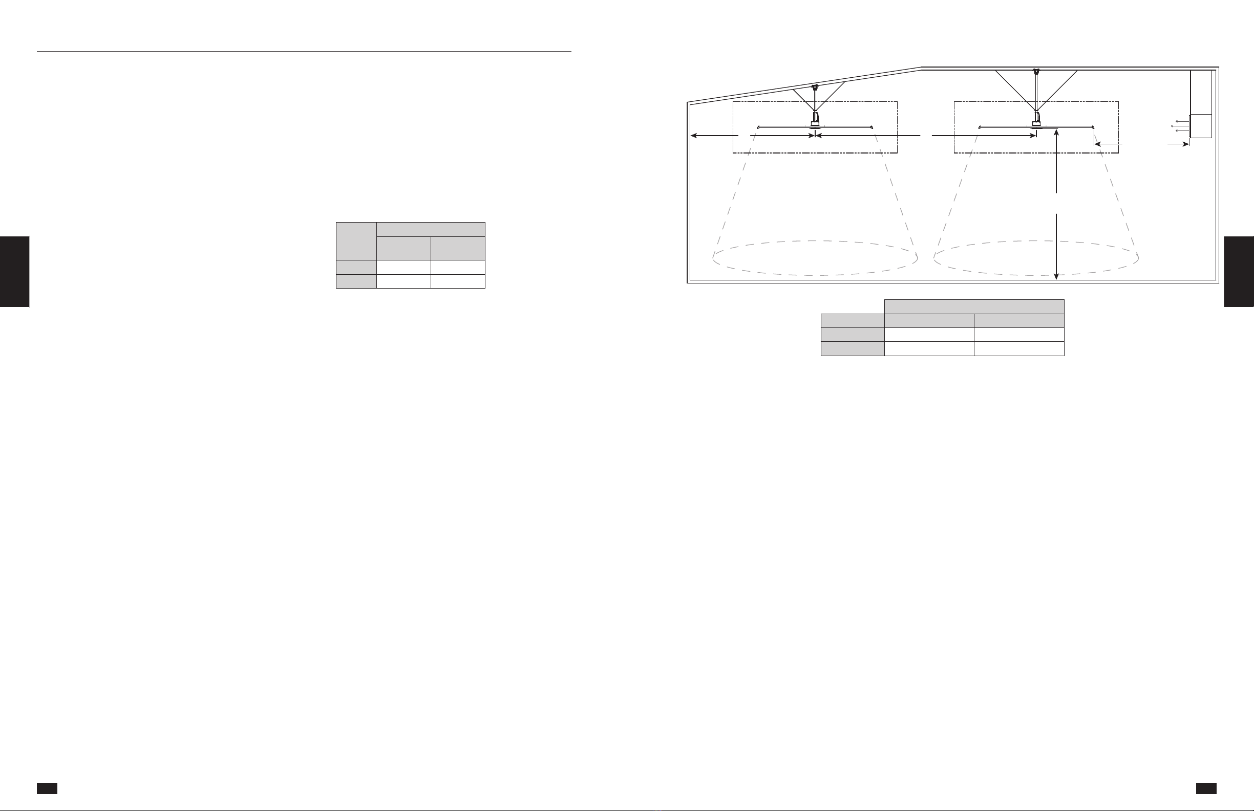
2. Verify that the fan is to be installed in a location
where the airfoils will be a minimum of 3 m.
above the finished floor with a minimum of 1
m. of horizontal and vertical clearance to any
obstructions.
3. Verify that the fan is to be installed in a location
where the center of the fan is a minimum of 1.5 fan
diameters away from building walls and corners.
4. For best performance, the fan must be installed
with a two fan diameter minimum clearance to
radiant heaters and HVAC system discharges or
intakes.
5. Check that the fan will not be mounted in a
location near overhead doors or other building
openings where gusts of wind may occur. Fan
should not be installed or operated in locations
where wind is present.
6. If the building is equipped with a fire sprinkler
system, verify that the placement of the fan will
not interfere with correct sprinkler operation and
that the fan installation complies with all national,
state and local codes. Fan must also be interlocked
to shut down upon receiving a waterflow signal
from the building’s alarm system.
7. Check to see if the intended placement of the fan
is directly below any building lights or skylights. If
possible, avoid installing fan directly below a light
source to prevent a strobing effect that can be
caused by fan rotation.
8. If the building has a mezzanine or other elevated
spaces that may be occupied by people, verify that
no component of the fan can be reached from the
highest level or deck. The fan must be positioned
so that the tips of the airfoils are a minimum of 1
m away from the furthest point that a person could
reach or otherwise come in contact, to prevent
injury.
9. If the fan is to be mounted in an area where
materials or equipment may be elevated into its
path, ensure that the floor is marked or painted
to alert personnel of the overhead location of the
fan(s).
10. Before installation, it is important to verify that the
mounting surface will bear the operating weight
and maximum torque (twisting force) of the unit. It
is the sole responsibility of the installer to ensure
that the mounting structure and fan installation
method are adequate for safe operation of the
fan.
Fan Size
m
AMPLIFY
*Max. Fan
Weight (kg)
Max. Torque
(Nm)
6 123 165
7,3 130 170
*Maximum weight is shown in
pounds and includes all available
options, actual fan weight may be
less.
Pre-Installation
Reference Troubleshooting Operation And
Maintenance
Fan
Networking
Electrical
Installation
Fire System
Integration
Mechanical
Installation Pre-Installation General
Information
Quick Start
Guide
B
A
1 M CLEARANCE AROUND BLADES
2X FAN DIAMETER
FROM HVAC
MINIMUM 3 M ABOVE
FINISHED FLOOR
HVAC
DIFFUSER
WHEN FULL DIFFUSER OUTLET
IS BELOW HVLS FAN,
HVLS FAN MUST BE 1X FAN DIAMETER AWAY
1 M CLEARANCE AROUND BLADES
Minimum Spacing From Center of Fan (m)
Fan Size (m) A B
6 9,2 18,3
7,3 11 22
Minimum Spacing Requirements
Quick Start
Guide
General
Information Pre-Installation Mechanical
Installation
Fire System
Integration
Electrical
Installation
Fan
Networking
Operation And
Maintenance Troubleshooting Reference
15
14
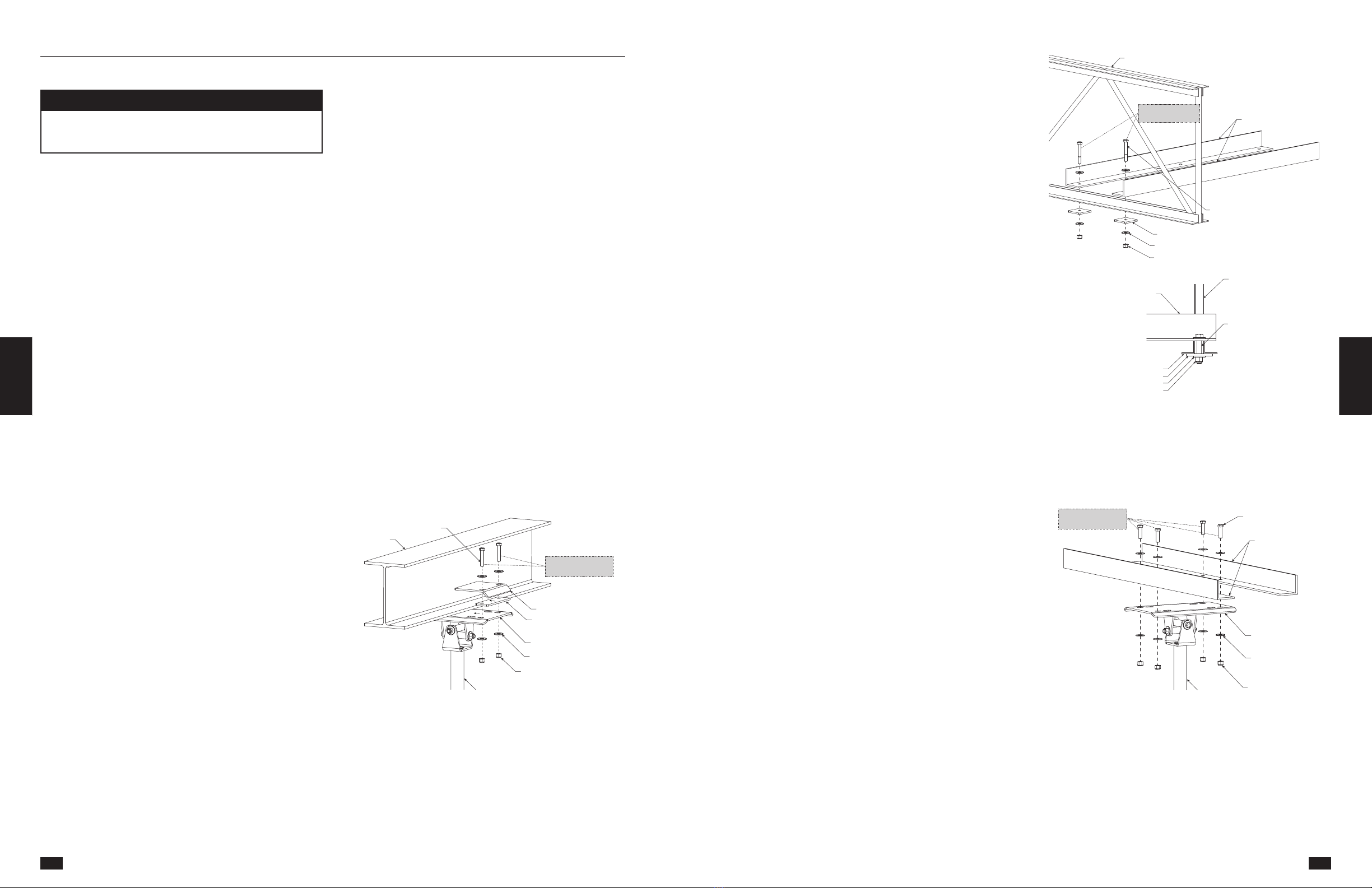
Mounting Installation
DANGER
Always disconnect, lock and tag power source before
installing or servicing. Failure to disconnect power
source can result in fire, shock or serious injury.
The following mounting installations are covered in this
manual. Identify the supplied mounting kit, locate the
appropriate installation within this manual.
• I-Beam Mounting Kit
• Steel Truss Mounting Kit
• Wood Beam Mounting Kit
I-Beam Mounting Kit
(For Flanges up to 250 mm Wide)
IMPORTANT: A Structural Engineer must perform
thorough evaluation of mounting structure and
determine final mounting requirements before fan is
installed. Manufacturer is not liable for any problems
that arise as the result of insufficient structure, including
(but not limited to) vibration, noise, or safety hazards.
Product warranty will be voided at manufacturer’s
discretion if structure is deemed insufficient.
Installations must comply with the following
requirements at a minimum, but The Structural
Engineer may require more stringent specifications at
their discretion:
• Do not install HVLS fans on fabricated I-beams.
• HVLS fans should only be installed on I-beams that
are part of the existing building structure.
• I-beam must have a minimum flange width of 130
mm and a minimum flange thickness of 13 mm.
• Do not weld HVLS fans to I-beams.
• Do not use I-beam mounting kit on any other type
of structure (steel trusses, steel angles, etc.).
Required Loose Components (Included):
• I-Beam Clamping Plate (2)
• I-Beam Clamping Plate Shim (2)
Required Components:
• Grade 8 Hex Bolt (4)
• Grade 8 Nylon Locknut (4)
• Washer (8)
Hardware/Tools Needed (Not Included):
• Torque Wrench
• Socket and Ratchet Kit
• Wrench
1. Using appropriate lifting equipment, raise the
downtube and mount assembly until the universal
mounting plate is positioned on the bottom of the
I-beam.
2. Using the universal mounting plate as a guide,
identify the appropriate set of mounting slots to
use for installation. The universal mounting plate
can accommodate I-beams with a flange width up
to 250 mm, a flange thickness up to 25 mm, and a
vertical web thickness up to 69 mm.
3. Attach (1) I-beam clamping plate shim and (1)
I-beam clamping plate to the universal mounting
plate using (2) grade 8 hex bolts, (4) washers,
and (2) grade 8 nylon locknuts. Hook the I-beam
clamping plate onto one side of the I-beam and
tighten hardware until the universal mounting
plate is snug against the beam but can still be
moved (approximately 6 mm of the bolt threads
exposed below the nylon locknut).
IMPORTANT: I-beam clamping plate shims and I-beam
clamping plates must be installed so that the laser-cut
arrows are pointing towards the I-beam. Ensure that
the narrowest possible set of mounting holes is used
on the universal mounting plate to ensure maximum
engagement with the I-beam.
I-BEAM CLAMPING PLATE
I-BEAM CLAMPING PLATE SHIM
UNIVERSAL MOUNTING PLATE
1/2 in. WASHER
1/2 in. - 13 GRADE 8 NYLON LOCKNUT
DOWNTUBE & MOUNT ASSEMBLY
GRADE 8 HEX BOLT
STEEL BEAM
TORQUE TO 45 FT∙LBF
(61.0 N∙m)
4. Attach the opposing I-beam clamp plate shim and
I-beam clamp plate on to the universal mounting
plate and I-beam. Hand tighten hardware.
5. Center the universal mounting plate under the
I-beam. Ensure the I-beam clamp plates have
maximum engagement on both sides and tighten
hardware evenly to 45 ftlbf (61.0 Nm).
6. Continue with Motor/Hub to Downtube
Installation.
Mechanical Installation Steel Truss Mounting Kit
IMPORTANT: A Structural Engineer must perform
thorough evaluation of mounting structure and
determine final mounting requirements before fan is
installed. Manufacturer is not liable for any problems
that arise as the result of insufficient structure, including
(but not limited to) vibration, noise, or safety hazards.
Product warranty will be voided at manufacturer’s
discretion if structure is deemed insufficient.
Installations must comply with the following
requirements at a minimum, but The Structural
Engineer may require more stringent specifications at
their discretion:
• Do not install HVLS fans on a single steel truss.
Structural steel angles must be used to span a
minimum of 2 trusses.
• Steel trusses must have a minimum chord width of
130 mm.
• Structural steel angle span lengths must not exceed
2,4 m. For span lengths up to 2,4 m, a minimum of
2 structural steel angles are required.
• Size of structural steel angles must be specified by
a structural engineer. Angles must be a minimum
of 100 x 100 x 6 mm thick. Larger angles may be
required for span lengths up to 2,4 m. Angles shall
be sufficiently stiff to avoid harmonic resonance
excitation during fan operation (120 RPM;
+/- 20%).
Required Loose Components (Included):
• Square Washer Plate (4)
Required Components:
• Grade 8 Hex Bolt (4)
• Grade 8 Nylon Locknut (8)
• Washer (16)
Hardware/Tools Needed (Not Included):
• Structural Steel Angles (2)
• Grade 8 Hex Bolt (4), length determined by truss
and steel angle material thickness
• Torque Wrench
• Socket and Wrench Kit
• Wrench
• Drill and 15 mm Drill Bit
1. Size structural steel angles (by others) to fit within
steel trusses/bar joists. Size of steel angle to be
determined by structural engineer.
2. Mount structural steel angles to steel trusses/bar
joists using (4) grade 8, M14 bolts (by others to
accommodate varying material thickness), and
supplied (8) washers, (4) square washer plates, and
(4) 14M nylon locknuts. Note that the hardware
should be installed through the gap in the bottom
chord of the steel trusses/bar joists (reference
drawing on to the right). Torque hardware to 80
ftlbf (108.5 Nm).
STEEL TRUSS / BAR JOIST
STRUCTURAL STEEL ANGLES
(BY OTHERS)
M14 GRADE 8 HEX BOLT
(BY OTHERS)
GRADE 8 NYLON LOCKNUT
SQUARE WASHER PLATE
WASHER
STRUCTURAL STEEL ANGLES
(BY OTHERS)
STEEL TRUSS / BAR JOIST
GRADE 8 HEX BOLT
(BY OTHERS)
STEEL TRUSS / BAR JOIST
SQUARE WASHER PLATE
WASHER
GRADE 8 NYLON LOCKNUT
TORQUE TO 80 FT∙LBF
(108.5 N∙m)
Lorem ipsum
STEEL TRUSS / BAR JOIST
STRUCTURAL STEEL ANGLES
(BY OTHERS)
1/2 in. - 13 GRADE 8 HEX BOLT
(BY OTHERS)
1/2 in. - 13 GRADE 8 NYLON LOCKNUT
SQUARE WASHER PLATE
1/2 in. WASHER
STRUCTURAL STEEL ANGLES
(BY OTHERS)
STEEL TRUSS / BAR JOIST
GRADE 8 HEX BOLT
(BY OTHERS)
STEEL TRUSS / BAR JOIST
SQUARE WASHER PLATE
WASHER
GRADE 8 NYLON LOCKNUT
3. Locate desired fan hanging location. Using the
universal mounting plate as a template, mark and
drill (4) 15 mm holes in structural steel angles.
4. Bolt universal mounting plate into place using
supplied (4) grade 8 hex bolts, (8) washers and (4)
grade 8 nylon locknuts. Torque to 80 ftlbf
(108.5 Nm).
STRUCTURAL STEEL ANGLES
(BY OTHERS)
GRADE 8 HEX BOLT
UNIVERSAL MOUNTING PLATE
DOWNTUBE & MOUNT ASSEMBLY
WASHER
GRADE 8 NYLON LOCKNUT
TORQUE TO 80 FT∙LBF
(108.5 N∙m)
5. Continue with Motor/Hub to Downtube
Installation.
Reference Troubleshooting Operation And
Maintenance
Fan
Networking
Electrical
Installation
Fire System
Integration
Mechanical
Installation Pre-Installation General
Information
Quick Start
Guide
Quick Start
Guide
General
Information Pre-Installation Mechanical
Installation
Fire System
Integration
Electrical
Installation
Fan
Networking
Operation And
Maintenance Troubleshooting Reference
17
16

Wood Beam Mounting Kit
(For Beams 115-225 mm Wide)
IMPORTANT: A Structural Engineer must perform
thorough evaluation of mounting structure and
determine final mounting requirements before fan is
installed. Manufacturer is not liable for any problems
that arise as the result of insufficient structure, including
(but not limited to) vibration, noise, or safety hazards.
Product warranty will be voided at manufacturer’s
discretion if structure is deemed insufficient.
Installations must comply with the following
requirements at a minimum, but The Structural
Engineer may require more stringent specifications at
their discretion:
• Do not use the wood beam mounting kit on wood
beams that are less than 115 mm wide. For thinner
wood beams, span two or more beams using
structural steel angles or unistrut. Refer to steel
truss or unistrut mounting kit instructions.
Required Loose Components (Included):
• Wood Beam Bracket (2)
Required Components:
• Grade 8 Hex Bolt (4)
• Grade 8 Nylon Locknut (8)
• Washer (16)
Hardware/Tools Needed (Not Included):
• M14 Grade 8 Hex Bolt (4), length determined by
wood beam thickness
• Torque Wrench
• Socket and Wrench Kit
• Wrench
• Drill and 15 mm Drill Bit
1. Locate desired fan hanging location. Using the
supplied wood beam brackets as a template, mark
and drill (4) 15 mm holes in the wood beam. Be
sure bottom of brackets are flush or slightly below
bottom of wood beam to effectively connect to
the universal mounting plate.
2. Bolt wood beam brackets into place using (4)
grade 8, M14 bolts (by others to accommodate
varying material thickness), and supplied (4) M14
nylon locknuts, and (8) washers. Torque hardware
to 80 ftlbf (108.5 Nm).
WASHER
M14 NYLON LOCKNUT
(BY OTHERS)
WOOD BEAM
WOOD BEAM
BRACKET
M14 GRADE 8 HEX BOLT
(BY OTHERS)
TORQUE TO 80 FT∙LBF
(108.5 N∙m)
3. With wood beam brackets installed, line up
universal mounting plate and bolt into wood beam
brackets using supplied (4) hex bolts, (8) 1/2 in.
washers, and (4) nylon locknuts.
WASHER
GRADE 8 NYLON LOCKNUT
WOOD BEAM
DOWNTUBE & MOUNT ASSEMBLY
GRADE 8 HEX BOLT
UNIVERSAL MOUNTING PLATE
TORQUE TO 80 FT∙LBF
(108.5 N∙m)
4. Torque hardware to 80 ftlbf (108.5 Nm).
5. Continue with Motor/Hub to Downtube
Installation.
Reference Troubleshooting Operation And
Maintenance
Fan
Networking
Electrical
Installation
Fire System
Integration
Mechanical
Installation Pre-Installation General
Information
Quick Start
Guide
Motor/Hub to Downtube Installation
Required Loose Components (Included):
• Motor/Hub Assembly (1)
• Rear VFD Cover (1)
Required Components:
• Grade 8 Hex Bolt (2)
• M4 – 0.7 x 10 Machine Screw (4)
Hardware/Tools Needed (Not Included):
• 14 mm Socket Kit
• Socket Wrench
• Torque Wrench
• Phillips Screwdriver
• Lifting Equipment
• Cribbing (optional)
• Awl (optional)
DANGER
Always disconnect, lock and tag power source before
installing or servicing. Failure to disconnect power
source can result in fire, shock or serious injury.
1. Using a scissor lift or other suitable lifting device, lift
the motor/hub assembly by resting the struts on the
lift structure or cribbing.
FRONT VFD COVER DOWNTUBE AND MOUNT ASSEMBLY
MOTOR AND HUB ASSEMBLY
2. Feed the safety retention cable that is attached to
the motor/hub assembly up through the bottom
of the downtube until the loose end of the safety
cable is accessible at the top of the downtube. Pull
the loose end of the safety retention cable from the
top of the downtube until all of the slack is pulled
through.
DOWNTUBE AND MOUNT ASSEMBLY
MOTOR AND HUB ASSEMBLY
SAFETY RETENTION CABLE
MOTOR POWER, GROUND AND
COMMUNICATION CABLES
4. Carefully align the motor axle with the downtube
opening, making sure that the electrical cables
protruding from the motor axle are on the same
side as the black plastic VFD cover.
IMPORTANT: Electrical cables from motor must be on
same side as black plastic VFD cover. Cables are not
long enough to reach circuit board from opposite side.
Motor must be removed and rotated 180° if installed
incorrectly.
5. Slowly lift the motor/hub assembly until the motor
axle is nested inside the downtube. Take care to
align the motor axle holes with the downtube holes.
IMPORTANT: Do not crush safety cable or wiring while
lifting the motor/hub assembly into the downtube.
If the safety cable or the wiring are damaged during
installation, contact your local rep or the manufacturer.
MOTOR AND HUB ASSEMBLY
DOWNTUBE AND MOUNT ASSEMBLY
Quick Start
Guide
General
Information Pre-Installation Mechanical
Installation
Fire System
Integration
Electrical
Installation
Fan
Networking
Operation And
Maintenance Troubleshooting Reference
19
18

6. Install the supplied (2) grade 8hex bolts into the
locknuts attached to the downtube. Torque the
bolts to a value of 33 ftlbf (44.75 Nm).
NOTE: The attached locknuts are not visible while the
VFD is installed on the downtube of the fan.
MOTOR AND HUB ASSEMBLY
DOWNTUBE AND MOUNT ASSEMBLY
3/8 in. - 16 x 2-3/4 in. GRADE 8 HEX BOLT
7. Install rear VFD cover to the back of the VFD using
(4) M4-0.7 x 10mm machine screws.
DOWNTUBE & MOUNT ASSEMBLY
MOTOR & HUB ASSEMBLY
FRONT VFD COVER
REAR VFD COVER
M4 - 0.7 x 10 MACHINE SCREW
Safety Retention Cable Installation
IMPORTANT: Do not put excessive tension on the
safety retention cable during installation. Safety
retention cable should be taut with only a small amount
of slack in the cable to ensure proper functioning. Do
not allow safety retention cable to contact any sharp
edges.
IMPORTANT: Failure to install the safety retention cable
will result in voiding of the fan warranty.
Standard Steel Cable Clamp
The following instructions apply to
standard fan installations. For fans that
were supplied with optional Gripple®
hardware, refer to the instructions.
Required Components
• U-Bolt Steel Cable Clamp (2)
Hardware/Tools Needed (Not
Included):
• Torque Wrench
• Socket and Wrench
• Cable Cutters (optional)
1. From the top of the downtube, pull the safety
retention cable until it is taut inside the downtube.
2. Wrap the loose end of the safety cable around
the mounting structure. Cable may be wrapped
around structure multiple times if length allows.
Do not allow the cable to come in contact with any
sharp edges.
3. Align the loose end of the safety cable (referred to
as the dead-end) with the length of cable that is
wrapped around the mounting structure (referred
to as the live-end).
4. Attach the dead-end of the safety cable to the live-
end using the supplied u-bolt steel cable.
IMPORTANT: The first steel cable clamp must be
installed a minimum of 140 mm away from the dead-
end of the safety cable to ensure proper functioning.
IMPORTANT: Steel cable clamps are composed of two
parts: the u-bolt and the saddle. Steel cable clamps
must be installed with the u-bolt over the dead-end
of the safety retention cable and the saddle over the
live-end of the safety cable. Failure to install steel cable
clamps in this manner may result in unsafe operating
conditions. Refer to drawing below for correct
orientation.
5. Pull the dead-end of the safety cable through the
steel cable clamps to tighten the cable. The cable
should be pulled taut, leaving only a small amount
of slack in the cable to ensure proper functioning.
6. Tighten the nuts on the steel cable clamps using
a socket and torque to 54 inlbf (6.10 Nm),
alternating between nuts until reaching proper
torque.
7. Cut or organize excess safety cable to ensure it
does not interfere with fan performance. Make
sure to leave at least 140 mm of cable between
the dead-end of the cable and the first steel cable
clamp to ensure proper functioning.
DOWNTUBE SAFETY CABLE
DOWNTUBE & MOUNT ASSEMBLY
CABLE CLAMP CABLE CLAMP
SADDLE
CABLE CLAMP U-BOLT
DEAD END
LIVE END
TORQUE TO 54 IN∙LBF
(6.10 N∙m)
140 MM.
Gripple®Hardware (Optional)
Components required:
• No. 4 Gripple®Connector (1)
Hardware/Tools (Not Included):
• 1/16 in. Allen Wrench (optional)
• Cable Cutters (optional)
1. From the top of the downtube, pull the safety
retention cable until the cable is taut inside the
downtube.
2. Insert the loose end of the safety cable into the
No. 4 Gripple connector. Note that the cable will
only feed through the Gripple connector in one
direction (marked on the Gripple connector with
an arrow).
3. Slide the No. 4 Gripple connector down the safety
cable until it is located near the opening at the top
of the downtube.
4. Wrap the loose end of the safety cable around
the mounting structure. Do not allow the cable to
come in contact with any sharp edges.
5. Insert the loose end of the safety cable into the
open hole of the No. 4 Gripple connector. Note
that the cable will only feed through the Gripple
connector in one direction (marked on the Gripple
connector with an arrow).
6. Pull the loose end of the safety cable through the
Gripple connector to tighten the cable. The cable
should be pulled taut, leaving only a small amount
of slack in the cable to ensure proper functioning.
7. Cut or organize excess safety cable to ensure it
does not interfere with fan rotation.
NOTE: If necessary, the safety cable can be loosened
by inserting the long end of a 1/16 in. allen wrench into
either of the pin holes on the No. 4 Gripple connector
and pulling the cable in the opposite direction of the
arrow marked on the Gripple connector.
DOWNTUBE SAFETY CABLE
DOWNTUBE SAFETY CABLE
DOWNTUBE & MOUNT ASSEMBLY
NO. 4 GRIPPLE
Quick Start
Guide
General
Information Pre-Installation Mechanical
Installation
Fire System
Integration
Electrical
Installation
Fan
Networking
Operation And
Maintenance Troubleshooting Reference
Reference Troubleshooting Operation And
Maintenance
Fan
Networking
Electrical
Installation
Fire System
Integration
Mechanical
Installation Pre-Installation General
Information
Quick Start
Guide
21
20

Guy Wire Installation
IMPORTANT: Guy wires must be installed 45º to 60º
from vertical to ensure proper functioning.
Standard Steel Cable Clamp
Required Loose Components (Included):
• 6 m Guy Wire (4)
Required Components:
• Guy Wire Clamp Assembly (4)
• Guy Wire Clamp Bolt (4)
• Quick Link (8)
• U-Bolt Steel Cable Clamp (8)
• Turnbuckle (4)
Hardware/Tools Needed (Not Included):
• Level
• Torque Wrench
• Socket and Wrench
• Socket and Wrench
• Adjustable Wrench
• Cable Cutters (optional)
1. Secure guy wire clamps to the building structure
using the guy wire clamp bolts and an adjustable
wrench. Attach guy wires to the eyelets on the guy
wire clamp assemblies using (4) supplied quick
links.
DOWNTUBE & MOUNT ASSEMBLY
UG2 GRIPPLE®TURNBUCKLE
GUY WIRE
GUY WIRE
GUY WIRE
GUY WIRE CLAMP ASSEMBLY
GUY WIRE CLAMP BOLT
45º to 60º
UG2 GRIPPLE®TURNBUCKLE
GUY WIRE ATTACHMENT RING
QUICK LINK
2. Insert the loose end of each guy wire through the
eyebolt on a turnbuckle. Turn the guy wire back
onto itself and align the loose end of the guy wire
(referred to as the dead-end) with the length of
guy wire that is attached to the building structure
(referred to as the live-end).
3. Attach the dead-end of each guy wire to the live-
end using (2) of the supplied u-bolt steel cable
clamps. Loosely tighten the nuts on the steel cable
clamps, leaving enough room for the guy wire to
slide through the steel cable clamps.
IMPORTANT: The first steel cable clamp must be
installed a minimum of 140 mm away from the dead-
end of the guy wire to ensure proper functioning.
IMPORTANT: Steel cable clamps consist of two parts:
the u-bolt and the saddle. Steel cable clamps must be
installed with the u-bolt over the dead-end of the guy
wire and the saddle over the live-end of the guy wire.
Failure to install steel cable clamps in this manner may
result in unsafe operating conditions. Refer to drawing
below for correct orientation.
TURNBUCKLE
45° TO 60°
DOWNTUBE AND
MOUNT ASSEMBLY
GUY WIRE
CABLE CLAMP
QUICK LINK
EYEBOLT
BEAM CLAMP ASSEMBLY
140 MM MIN.
CABLE CLAMP U- BOLT
DEAD END
LIVE END
CABLE CLAMP SADDLE
O
4. Attach all (4) turnbuckles to the guy wire
attachment ring located on the downtube using
(4)supplied quick links.
5. Pull the dead-end of each guy wire through the
steel cable clamps until taut.
6. Tighten the nuts on the steel cable clamps using
a socket and torque to 54 inlbf (6.10 Nm),
alternating between nuts until reaching proper
torque.
7. Place a level against the downtube and tighten all
(4) turnbuckles by hand in a crisscross pattern until
the guy wires are tight and the fan is level.
NOTE: When leveling the fan, place the level against
the downtube in-between two neighboring guy wires
to simplify the leveling process. The level should also
be moved around the circumference of the downtube
periodically to ensure that the fan is level in all
directions.
8. Cut or organize excess guy wires to ensure that
they do not interfere with fan performance. Make
sure to leave at least 140 mm of wire between the
dead-end of the guy wire and the first wire rope
clip to ensure proper functioning.
Gripple®Hardware (Optional)
IMPORTANT: Guy wires must be installed 45º to 60º
from vertical to ensure proper functioning.
Required Loose Components (Included):
• 6 m Guy Wire (4)
• No. 4 Gripple®Connector (4)
Components required:
• Guy Wire Clamp Assembly (4)
• Guy Wire Clamp Bolt (4)
• Quick Link (8)
• Turnbuckle (4)
Hardware/Tools Needed (Not Included):
• Adjustable Wrench
• Level
• Allen Wrench (optional)
1. Secure guy wire clamps to the building structure
using the guy wire clamp bolts. Attach guy wires
to the eyelets on the guy wire clamp assemblies
using (4) supplied quick links.
DOWNTUBE & MOUNT ASSEMBLY
UG2 GRIPPLE®TURNBUCKLE
GUY WIRE
GUY WIRE
GUY WIRE
GUY WIRE CLAMP ASSEMBLY
GUY WIRE CLAMP BOLT
45º to 60º
UG2 GRIPPLE®TURNBUCKLE
GUY WIRE ATTACHMENT RING
QUICK LINK
2. Insert the loose end of each guy wire into a No. 4
Gripple connector until a length of wire is pushed
through the connector. Insert the loose end of the
guy wire through the end of the turnbuckle and
push back through the No. 4 Gripple connector to
close the loop.
3. Attach all (4) turnbuckles to the guy wire
attachment ring located on the downtube using
(4) supplied quick links. Pull the loose end of each
guy wire through the No. 4 Gripple connector until
each guy wire is taut.
TURNBUCKLE
45° TO 60°
DOWNTUBE AND MOUNT ASSEMBLY
GUY WIRE
No. 4 GRIPPLE CONNECTOR
QUICK LINK
EYEBOLT
BEAM CLAMP ASSEMBLY
4. Place a level against the downtube and tighten
all (4) turnbuckles by hand in a crisscross pattern
until the guy wires are tight and the fan is level.
NOTE: When leveling the fan, place the level against
the downtube in-between two neighboring guy wires
to simplify the leveling process. The level should also
be moved around the circumference of the downtube
periodically to ensure that the fan is level in all
directions.
5. Cut or organize excess guy wires to ensure that
they do not interfere with fan rotation.
NOTE: If necessary, the guy wires can be loosened by
inserting the long end of a 1/16 in. allen wrench into
either of the pin holes on the No. 4 Gripple connector
and pulling the cable in the opposite direction of the
arrow marked on the Gripple connector.
Airfoil Blade and Winglet Installation
IMPORTANT: Do not operate fans without the airfoil
blades. Failure to comply with this warning will result
in voiding of the product warranty and may result in
permanent damage to the VFD and motor.
WARNING
To reduce the risk of personal injury, do not bend
motor struts, airfoil blades, or airfoil retaining links
when installing the airfoil blades, balancing the blades,
or cleaning the fan. Damage to these components may
result in unsafe operation of the fan, which can lead
to property damage, personal injury or death. Contact
your local representative or the factory if replacement
parts are needed.
WARNING
To reduce the risk of personal injury, do not insert
foreign objects in between rotating fan blades.
Required Loose Components (Included):
• Airfoil Blade (6)
• Winglet (6)
Required Components:
• #10 – 12 x 3/4 in. Screw (12)
• Washers (24)
• Grade 8 Nylon Locknut (12)
• Grade 8 Hex Bolt (12)
Hardware/Tools Needed (Not Included):
• Socket and Socket Wrench
• Wrench
• Torque Wrench
• #2 Phillips Bit and Driver
Reference Troubleshooting Operation And
Maintenance
Fan
Networking
Electrical
Installation
Fire System
Integration
Mechanical
Installation Pre-Installation General
Information
Quick Start
Guide
Quick Start
Guide
General
Information Pre-Installation Mechanical
Installation
Fire System
Integration
Electrical
Installation
Fan
Networking
Operation And
Maintenance Troubleshooting Reference
23
22
1. Install one winglet per airfoil blade using the screw
bosses located in each blade on the opposite end
from the mounting holes. Use a #2 phillips bit to
install (2) screws per winglet. Torque screws to 60
inlbf (6.8 Nm).
AIRFOIL BLADE
SCREW BOSSES
WINGLET
SCREW
(2 PER BLADE)
NOTE: Improperly fastened winglets may result in
unwanted noise.
2. Lift the first blade into place, and slide over the
motor strut allowing the airfoil retaining ring
to rest on top of the airfoil blade. It might be
necessary to use two people for this step.
5/16 in. WASHER
(2 PER BLADE)
5/16 in. - 18 GRADE 8 NYLON LOCKNUT
(2 PER BLADE)
MOTOR & HUB ASSEMBLY
5/16 in. - 18 x 2 GRADE 8 HEX BOLT
(2 PER BLADE)
MOTOR STRUT
AIRFOIL BLADE
AIRFOIL RETAINING RING SHIM
AIRFOIL BLADE
AIRFOIL RETAINING RING
AIRFOIL RETAINING RING
3. With the blade in position on the motor strut,
install (2) hex bolts, (4) washers, and (2) 18 nylon
locknuts per blade as shown below. Hand tighten
hardware.
WASHER
(2 PER BLADE)
GRADE 8 NYLON LOCKNUT
(2 PER BLADE)
MOTOR & HUB ASSEMBLY
GRADE 8 HEX BOLT
(2 PER BLADE)
MOTOR STRUT
AIRFOIL BLADE
AIRFOIL BLADE
AIRFOIL RETAINING RING
AIRFOIL RETAINING RING
AIRFOIL RETAINING RING SHIM
4. Repeat steps 1 through 3 on remaining airfoil
blades. Torque the installed bolts to 25 ftlbf
(34Nm).
GRADE 8 BOLT
(2 PER BLADE)
TORQUE TO 25 FT∙LBF
(34 N∙m)
IMPORTANT: If airfoils must be removed and reinstalled
for any reason, do not re-use the supplied nylon
locknuts. Re-use increases the risk of locknuts loosening
during operation, which may result in unwanted noise
and/or unsafe operation of the fan. Contact your local
representative or the factory if replacement parts are
needed.
Hub Plate Installation
Required Loose Components (Included):
• Hub Plate (1)
Required Components:
• Machine Screw (4)
Hardware/Tools Needed (Not Included):
• Torque Wrench
1. Align (4) holes in the faceplate with the (4) U-nuts
on the hub retention bracket.
2. Insert (1) machine screw per hole and hand tighten
to ensure all fasteners will engage the U-nuts.
3. Torque fasteners to 96 inlbf (10.8 Nm).
HUB PLATE
U-NUT
HUB RETENTION BRACKET
MACHINE SCREW
IMPORTANT: Rotate fan impeller by hand to ensure that
it rotates freely and does not rub on hub plate or come
into contact with any obstructions.
Fire System Integration
Fire System Integration (Optional)
The following instructions apply to fans that were
supplied with plug-and-play factory wiring, for fire
system integration.
DANGER
Always disconnect, lock and tag power source before
installing or servicing. Failure to disconnect power
source can result in fire, shock or serious injury.
NOTE: The following instructions are only applicable
to buildings that are equipped with a fire suppression
system. If the building does not contain a fire
suppression system, leave the crimp connector on
the fire alarm landing point (located at the top of the
downtube) and continue with the rest of the installation.
IMPORTANT: HVLS fans must be installed with the
supplied, normally-closed PAM-1 fire alarm relay or an
equivalent electromechanical or reed relay for proper
function of the fire alarm emergency stop feature. Solid
state relays or other digital switching relays cannot be
used.
IMPORTANT: The fire alarm relay should only be
installed by qualified personnel who are familiar with
the operation of building fire suppression systems. It is
the sole responsibility of the installer to ensure correct
operation of the fire alarm relay in the event of a fire
emergency in the building.
Required Loose Components (Included):
• Low Voltage (24VDC/VAC), Normally Closed Relay
(1)
Hardware/Tools Needed (Not Included):
• Standard Screwdriver
• Cable Cutters
• Wire Strippers
1. If the building is equipped with a fire suppression
system, remove the crimp connector from the fire
alarm emergency stop landing point located at the
top of the downtube by snipping the wires directly
below the crimp connector.
2. Strip the loose wires and wire the supplied
normally-closed relay to the fire alarm emergency
stop landing point and the building’s fire
suppression system using the wiring diagram
shown.
FIRE RELAY
RED (+)
WHITE (-)
YELLOW (NC)
BLUE (COMMON)
BLACK
RED
FIRE ALARM
CONTROL PANEL
RED
WHITE
Quick Start
Guide
General
Information Pre-Installation Mechanical
Installation
Fire System
Integration
Electrical
Installation
Fan
Networking
Operation And
Maintenance Troubleshooting Reference
Reference Troubleshooting Operation And
Maintenance
Fan
Networking
Electrical
Installation
Fire System
Integration
Mechanical
Installation Pre-Installation General
Information
Quick Start
Guide
25
24
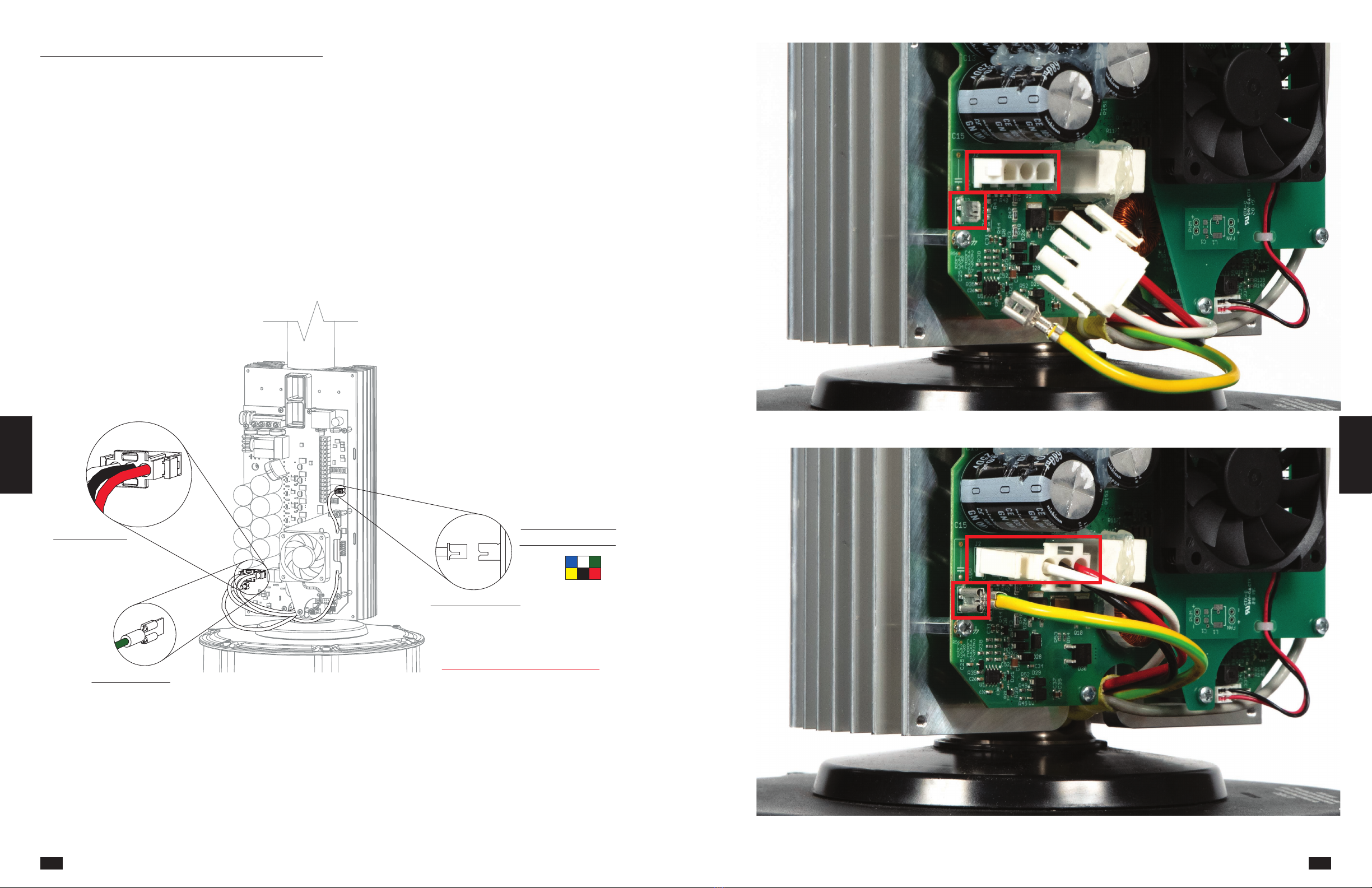
Electrical Installation
Motor Cable Connection
1. Using a phillips screwdriver, remove the black
plastic cover on the front side of the VFD and set
aside.
2. Locate the motor power, motor ground, and hall
sensor cables that protrude from the top side
of the motor. These cables should have been
routed to the front of the VFD during mechanical
installation.
3. Plug the motor power, motor ground, and hall
sensor cables into the VFD circuit board as shown
below. The motor power and hall sensor cables
are designed to only fit in one orientation. Use the
wire color references below and photos on the
next two pages to identify the proper orientation.
Do not force these plugs.
IMPORTANT: The motor power, motor ground, and hall
sensor cables are not long enough to reach the VFD
circuit board from the rear side. If the cables are not
properly routed to the front of the VFD, the motor must
be uninstalled and rotated 180° so that the cables can
be connected.
HALL CABLE COLOR
PINOUT REFERENCE
HALL CONNECTION
NOTE: HALL CABLE PLUG
HAS BUILT-IN ALIGNMENT TAB
DO NOT FORCE THIS PLUG
MOTOR GROUND
MOTOR POWER
Reference Troubleshooting Operation And
Maintenance
Fan
Networking
Electrical
Installation
Electrical
Installation
Electrical
Installation Pre-Installation General
Information
Quick Start
Guide
Motor Power and Ground Cable Connection
Quick Start
Guide
General
Information Pre-Installation Mechanical
Installation
Electrical
Installation
Electrical
Installation
Fan
Networking
Operation And
Maintenance Troubleshooting Reference
27
26

Hall Sensor Cable Connection
Power Wiring
DANGER
Always disconnect, lock and tag power source before
installing or servicing. Failure to disconnect power
source can result in fire, shock or serious injury.
IMPORTANT: Do not apply power until mechanical
installation, fire alarm relay installation, communication
wiring and fan control installation are complete.
IMPORTANT: Do not apply power to the fan above the
rated voltage of the variable frequency drive (VFD).
Failure to comply with this warning will result in voiding
of the product warranty and may result in permanent
damage to the VFD and motor.
IMPORTANT: To prevent electrical failures, source
power must comply with the following power quality
requirements. If source power falls outside of these
specified tolerances, an external power line filter will be
required (by others). If other power quality issues are
present, contact the factory for support.
Allowable Voltage
Fluctuation +/- 10% of nominal
Allowable Frequency
Fluctuation +/- 5% of nominal (47-63 Hz)
Area of Use
Do not install fans in electrical environments
with Pollution higher than Degree 2 in
accordance with UL 61800-5-1
Surge Immunity
Do not install fans in electrical environments
above Installation Class 3 in accordance
with IEC 61000-4-5
Hardware/Tools Needed (Not Included):
• Phillips Screwdriver
With Optional Electrical Plug
1. If the fan is supplied with the optional electrical
plug for power wiring, refer to the chart below for
the corresponding receptacle that will be needed
(provided by others).
Electrical Plug Reference (Locking)
Voltage Phase Plug* Receptacle
208-230 1 L6-30P L6-30R
277 1 L7-30P L7-30R
208-230 3 L15-30P L15-30R
460 3 L16-30P L16-30R
*NOTE: Plugs are available from manufacturer. Receptacles must be
provided by others.
2. Install the receptacle according to all national and
local codes for electrical wiring.
3. Insert the electrical plug into the receptacle and
twist to lock the plug in place.
4. Secure any loose power cable to the building
structure to ensure it does not interfere with fan
performance.
Without Optional Electrical Plug
1. If the fan is not supplied with the optional
electrical plug, refer to the wiring diagrams below
to complete power wiring.
2. Secure any loose power cable to the building
structure to ensure it does not interfere with fan
performance.
RED
BLACK
WHITE
GREEN
POWER SOURCE
L3
L2
L1
GROUND
BLACK
WHITE
GREEN
POWER SOURCE
L2
L1
GROUND
1-PHASE INPUT POWER
OR
3-PHASE INPUT POWER
Disconnect and Fuse Installation
1. If provided, mount and wire the optional safety
disconnect switch outside of the sweep of the fan’s
airfoil blades. Installation should be completed per
the disconnect manufacturer’s recommendation.
Be sure to follow all national and local codes for
electrical installation.
2. Fusing is required unless otherwise specified
by local authority. Refer to the fuse sizing chart
below and install fuses per the manufacturer’s
recommendation. If the fan was supplied with the
optional fused disconnect, the fuses received will
match the models shown. Be sure to follow all
national and local codes for electrical installation.
IMPORTANT: Warranty may be voided at manufacturer’s
discretion if correct fuses are not installed.
Fuse Sizing Chart
Amplify 6 and 7,3
1100W Motor
Motor Voltage 208-230V/
1,3 PH/60 HZ
277V/
1 PH/60 HZ
460V/
3 PH/60 HZ
Motor Full Load Amps
(FLA)* 12A 12A 3.3A
Fuse Required** FRN-R-15 FRS-R-15 FRS-R-5
*FLA is based on worst case system conditions assuming lowest
nominal voltage and phase.
** Fuses shown are available as an optional accessory. Fuses
provided by others must meet requirements of all national and local
codes.
Quick Start
Guide
General
Information Pre-Installation Mechanical
Installation
Fire System
Integration Power Wiring Fan
Networking
Operation And
Maintenance Troubleshooting Reference
Reference Troubleshooting Operation And
Maintenance
Fan
Networking
Electrical
Installation
Electrical
Installation
Electrical
Installation Pre-Installation General
Information
Quick Start
Guide
29
28
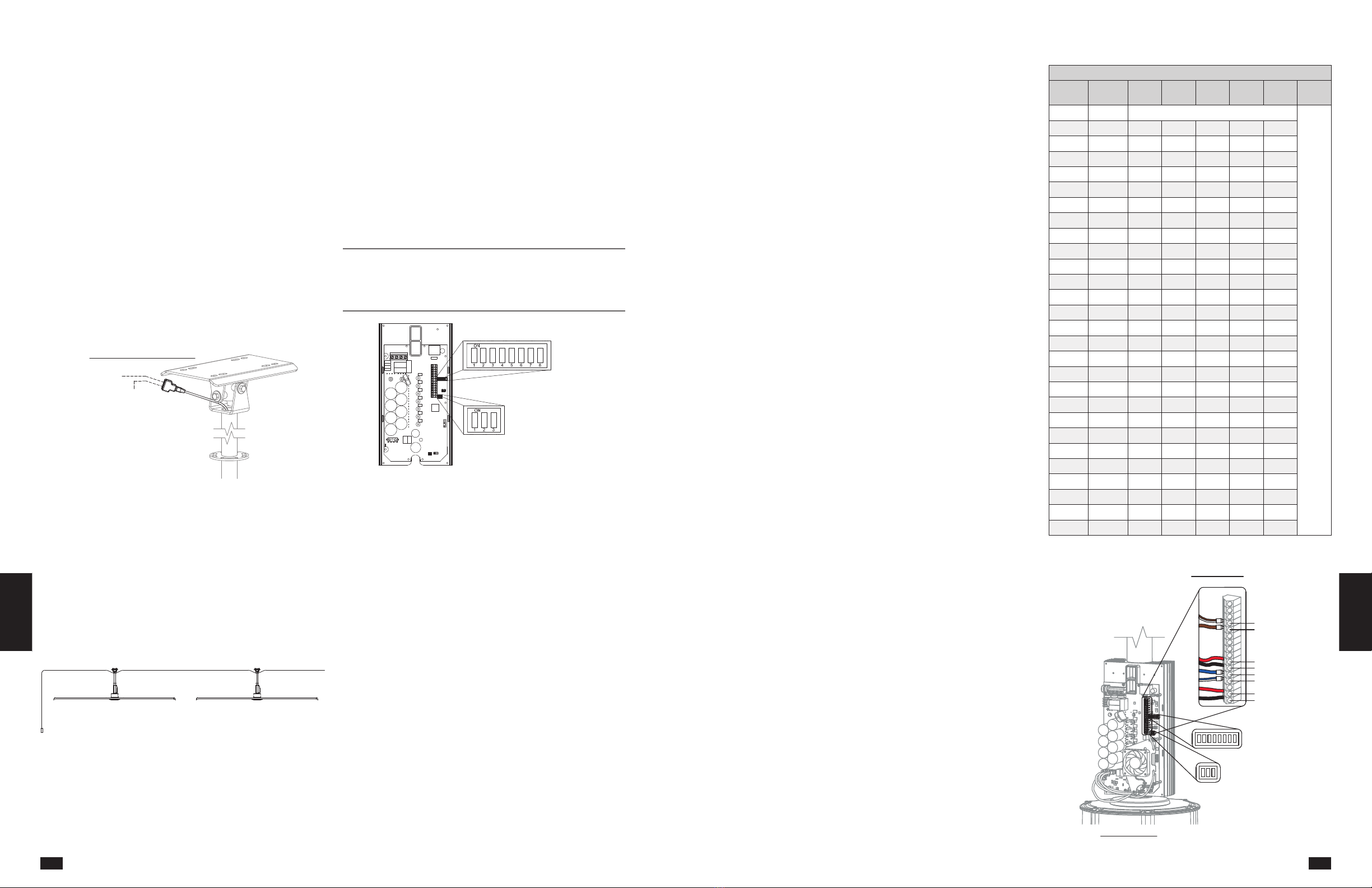
Communication Wiring
IMPORTANT: Amplify fans not installed with Northern
Sky must be installed with the supplied CAT-5/6
communication cable or shielded CAT-5/6 (by others)
that complies with the following specifications. Cable
must be twisted pair, shielded 26 ga. CAT-5/6 cable
with a drain wire and must be compliant with ISO
11801. Cable must use shielded RJ45 connectors
with a soldered drain Individual CAT-5/6 cable lengths
must not exceed 60 m in order to prevent network
communication issues.
With Pre-Built CAT-5/6 Cable
Required Loose Components:
• 30-60 m CAT-5/6 Control Cable (1)
1. Plug one end of the shielded CAT-5/6 control cable
into the 2-way RJ45 splitter located at the top of
the downtube. The cable can be plugged into any
open receptacle on the splitter.
TO NEXT FAN
(IF APPLICABLE)
TO CONTROL
SHIELDED CAT 5/6 CONNECTION
2. Identify the desired location for installation of the
fan control and run the remainder of the CAT-5/6
control cable to this location.
3. Secure the CAT-5/6 control cable to the building
structure to ensure it does not interfere with fan
performance. To prevent communication issues, do
not coil excess control cable or route control cable
with power wiring.
4. If one control source will be used to operate
multiple fans, the fans can be daisy-chained
together to create a network using the following
instructions.
FAN 1
CONTROL
FAN 2
a. Connect a shielded CAT-5/6 control cable to
the first fan in the daisy-chain using steps 1-3
above.
b. Plug an additional CAT-5/6 control cable into
the 2-way RJ45 splitter located at the top of the
downtube on the first fan. Connect the other
end of this CAT-5/6 cable into the 2-way splitter
on the next fan.
c. Repeat step 4b. for subsequent fans until all
fans in the chain are connected in series.
d. Follow the “Fan Networking” instructions to
complete network setup for the fans.
Fan Networking
If networking multiple fans to run using a single control
source, the dipswitch settings and wiring on each fan’s
VFD circuit board will need to be adjusted using the
following instructions.
DIPSWITCH 3
DIPSWITCH 2
First Fan
1. Determine the first fan in the network daisy-
chain by identifying the fan that will be directly
connected to the control source.
2. Dipswitch 2 is used to set parameters that improve
network function. Verify that each of the switches
on dipswitch 2 are set as follows:
Position 1 – Off
Position 2 – On
Position 3 – On
3. Dipswitch 3 is used to set unique Modbus
addresses for each fan in the daisy-chain. Adjust
positions 1-5 on dipswitch 3 to set the desired
Modbus address. A table with all possible Modbus
addresses is shown to the right.
Reference Troubleshooting Operation And
Maintenance
Fan
Networking
Electrical
Installation
Fire System
Integration
Mechanical
Installation Pre-Installation General
Information
Quick Start
Guide
IMPORTANT: Positions 6 - 8 are used to set parameters
needed for fan operation and should not be adjusted.
Default settings are as follows:
Position 6 – On
Position 7 – Off
Position 8 – Off
4. Verify that the low voltage wiring terminal strip
on the VFD circuit board is wired as shown in the
diagram and picture (First Fan). Reinstall the black
plastic cover that was previously set aside on the
front of the VFD.
Modbus Address Settings - Dipswitch 3
Fan
Number
Modbus
Address
Position
1
Position
2
Position
3
Position
4
Position
5
Position
6, 7, 8
N/A 1 RESERVED FOR HVLS FAN CONTROLS
Do Not
Modify
1 2 On Off Off Off Off
2 3 Off On Off Off Off
3 4 On On Off Off Off
4 5 Off Off On Off Off
5 6 On Off On Off Off
6 7 Off On On Off Off
7 8 On On On Off Off
8 9 Off Off Off On Off
9 10 On Off Off On Off
10 11 Off On Off On Off
11 12 On On Off On Off
12 13 Off Off On On Off
13 14 On Off On On Off
14 15 Off On On On Off
15 16 On On On On Off
16 17 Off Off Off Off On
17 18 On Off Off Off On
18 19 Off On Off Off On
19 20 On On Off Off On
20 21 Off Off On Off On
21 22 On Off On Off On
22 23 Off On On Off On
23 24 On On On Off On
24 25 Off Off Off On On
25 26 On Off Off On On
26 27 Off On Off On On
27 28 On On Off On On
GND
FIRE +
FIRE -
DATA +
DATA -
0-10V
GND (OPTIONAL)
ALL OTHER FANS IN SERIES
GND
FIRE +
FIRE -
DATA +
DATA -
0-10V
GND (OPTIONAL)
LOW VOLTAGE WIRING
24v
FIRST FAN IN SERIES
LOW VOLTAGE WIRING
DIP SWITCH BANK 2
1 2 345 6 78
ON
1 2 3
ON
DIP SWITCH BANK 3
DIP SWITCH BANK 2
1 2 345 6 78
ON
1 2 3
ON
DIP SWITCH BANK 3
EF
Quick Start
Guide
General
Information Pre-Installation Mechanical
Installation
Fire System
Integration
Electrical
Installation
Fan
Networking
Operation And
Maintenance Troubleshooting Reference
31
30

First Fan
Reference Troubleshooting Operation And
Maintenance
Fan
Networking
Electrical
Installation
Fire System
Integration
Mechanical
Installation Pre-Installation General
Information
Quick Start
Guide
All Remaining Fans
1. Set dipswitch 2 as shown below. Dipswitch 2 is
used to set parameters that improve network
function and will need to be adjusted for all fans in
the network except for the first fan.
Position 1 – Off
Position 2 – Off
Position 3 – Off
2. Adjust positions 1 – 5 on dipswitch 3 so that each
successive fan has a unique Modbus address. A
table with all possible Modbus addresses is shown
to the right.
IMPORTANT: Positions 6 - 8 are used to set parameters
needed for fan operation and should not be adjusted.
Default settings are as follows:
Position 6 – On
Position 7 – Off
Position 8 – Off
NOTE: It is good practice to use successive Modbus
addresses for networked fans, but this is not necessary
for proper functioning of the network.
3. On the low voltage wiring terminal strip, remove
the 24V (white-brown) wire and cap with a wire
nut or heat shrink. When complete, verify that the
low voltage wiring terminal strip on the VFD circuit
board is wired as shown in the diagram and picture
(All Remaining Fans).
4. Reinstall the black plastic cover that was previously
set aside on the front of the VFD.
Modbus Address Settings - Dipswitch 3
Fan
Number
Modbus
Address
Position
1
Position
2
Position
3
Position
4
Position
5
Position
6, 7, 8
N/A 1 RESERVED FOR HVLS FAN CONTROLS
Do Not
Modify
1 2 On Off Off Off Off
2 3 Off On Off Off Off
3 4 On On Off Off Off
4 5 Off Off On Off Off
5 6 On Off On Off Off
6 7 Off On On Off Off
7 8 On On On Off Off
8 9 Off Off Off On Off
9 10 On Off Off On Off
10 11 Off On Off On Off
11 12 On On Off On Off
12 13 Off Off On On Off
13 14 On Off On On Off
14 15 Off On On On Off
15 16 On On On On Off
16 17 Off Off Off Off On
17 18 On Off Off Off On
18 19 Off On Off Off On
19 20 On On Off Off On
20 21 Off Off On Off On
21 22 On Off On Off On
22 23 Off On On Off On
23 24 On On On Off On
24 25 Off Off Off On On
25 26 On Off Off On On
26 27 Off On Off On On
27 28 On On Off On On
GND
FIRE +
FIRE -
DATA +
DATA -
0-10V
GND (OPTIONAL)
ALL OTHER FANS IN SERIES
GND
FIRE +
FIRE -
DATA +
DATA -
0-10V
GND (OPTIONAL)
LOW VOLTAGE WIRING
24v
FIRST FAN IN SERIES
LOW VOLTAGE WIRING
DIP SWITCH BANK 2
1 2 345 6 78
ON
1 2 3
ON
DIP SWITCH BANK 3
DIP SWITCH BANK 2
1 2 345 6 78
ON
1 2 3
ON
DIP SWITCH BANK 3
EF
Quick Start
Guide
General
Information Pre-Installation Mechanical
Installation
Fire System
Integration
Electrical
Installation
Fan
Networking
Operation And
Maintenance Troubleshooting Reference
33
32

All Remaining Fans
Reference Troubleshooting Operation And
Maintenance
Fan
Networking
Electrical
Installation
Fire System
Integration
Mechanical
Installation Pre-Installation General
Information
Quick Start
Guide
Pre-Start-Up Checks
1. Disconnect and lock-out all power switches to fan.
2. Check all fasteners on the ceiling mount, mounting
kit, blades, VFD, motor and accessories for
tightness.
3. Rotate the fan impeller by hand to ensure that it
rotates freely and does not come into contact with
any obstructions.
4. Check all electrical connections for proper
attachment.
5. Verify that the fan is hanging so that the airfoils
and downtube are level and the fan is plumb to
the floor. Adjust guy wire tension as necessary (if
applicable).
Fan Operation
IMPORTANT: If unusual vibration or oscillating
movement is observed during fan operation,
immediately discontinue use of the fan and contact the
manufacturer or a suitably qualified maintenance/repair
technician.
1. When the fan is started, observe the operation
and check for any unusual noise, vibration or
overheating. Refer to the Troubleshooting section
of this manual if a problem develops.
2. With the system in full operation, measure current
input to the VFD and compare with the FLA ratings
in the table above to determine if the motor/VFD
system is operating under safe load conditions.
3. Keep approaches to fan clean and free from
obstruction.
Fan Inspection
DANGER
Disconnect and secure to the ‘OFF’ position all
electrical power to the fan prior to inspection or
servicing. Failure to comply with this safety precaution
could result in serious injury or death.
Inspection of the fan should be conducted at the first
30 minute and 24 hour intervals of satisfactory
operation.
• 30 Minute Interval - Check all fasteners for
tightness. Adjust and tighten as necessary.
• 24 Hour Interval - Inspect all fan components.
Check all fasteners, airfoil retaining ring, the safety
cable, and guy wires (if applicable). Adjust and
tighten as necessary.
Fan Maintenance
NOTE: Installation and maintenance are to be
performed only by qualified personnel who are familiar
with local codes and regulations and have experience
with this type of equipment.
Once the fan has been put into operation, a periodic
maintenance program should be set up to ensure
reliable fan performance. A proper maintenance
program will help deliver years of dependable service.
Items to be included in this program are as follows:
1. Verify that all fasteners are tight and properly
torqued.
2. Verify that all of the fan’s safety systems – safety
cable, airfoil retaining ring, and guy wires (if
applicable) are properly installed. Inspect for
signs of damage or failure. Safety cable and guy
wire tension should also be checked. Safety cable
should be wrapped around the building structure
leaving as little slack as possible. Guy wires
should be under enough tension to prevent any
lateral movement of the motor and downtube (if
applicable).
3. Inspect the fan for signs of fatigue, corrosion, or
wear.
4. Impellers require little attention when moving
clean air. Occasionally, oil and dust may
accumulate causing imbalance. When this occurs,
clean the impeller and other fan components to
ensure smooth and safe operation. Remove any
accumulated dust and dirt using hot water or mild
cleaning solutions. Harsh chemicals should not
be used to clean the fan as they may damage the
fan’s finish or motor.
IMPORTANT: Do not allow water or solvents to enter
the motor or VFD. Under no circumstances should
motors or VFDs be sprayed with steam, water or
solvents.
5. Motor maintenance is generally limited to
cleaning. Limit cleaning to exterior surfaces only.
Removing dust buildup on motor housing ensures
proper motor cooling.
6. Prior to restarting unit, check all fasteners for
tightness each time maintenance checks are
performed.
Operation And Maintenance
Quick Start
Guide
General
Information Pre-Installation Mechanical
Installation
Fire System
Integration
Electrical
Installation
Fan
Networking
Operation And
Maintenance Troubleshooting Reference
35
34

Address
Nordicco A/S
Strevelinsvej 22
7000 Fredericia
Denmark
contact
+45 73 70 90 83
info@nordicco.eu
www.nordicco.eu
Comp. Reg. No.:
DK36085118
Downloads
Other manuals as well as manuals in other languages can be downloaded
from our website: www.nordicco.eu/downloads
Table of contents
Other NORDICCO Fan manuals

NORDICCO
NORDICCO NORTHERN AIR 200 Guide

NORDICCO
NORDICCO NORTHERN LIGHT HVLS User manual

NORDICCO
NORDICCO NORTHERN AIR MINI User manual

NORDICCO
NORDICCO HVLS Series User manual

NORDICCO
NORDICCO NORTHERN LIGHT User manual

NORDICCO
NORDICCO NORTHERN AIR MINI User manual

NORDICCO
NORDICCO NORTHERN LIGHT Guide

NORDICCO
NORDICCO HVLS Guide

NORDICCO
NORDICCO AIR MINI User manual
Popular Fan manuals by other brands


Bestron
Bestron AFT760W instruction manual

Russell Hobbs
Russell Hobbs RHMF40 Instructions and warranty

Home Decorators Collection
Home Decorators Collection TOLEDO 52-PLM Use and care guide

Unold
Unold 86820 Instructions for use

emerio
emerio FN-114894.2 instruction manual

Fanimation
Fanimation ZONIX WET FP4640B Series manual


