NORDICCO AIR MINI User manual

INSTALLATION MANUAL
NORDICCO NORTHERN AIR®MINI
ENGLISH
Vers. 1.0


C
C
a
a
u
u
t
t
i
i
o
o
n
n
&
&
S
S
a
a
f
f
e
e
t
t
y
y
W
W
A
A
R
R
N
N
I
I
N
N
G
G
-
-
T
T
O
O
R
R
E
E
D
D
U
U
C
C
E
E
T
T
H
H
E
E
R
R
I
I
S
S
K
K
O
O
F
F
E
E
L
L
E
E
C
C
T
T
R
R
I
I
C
C
S
S
H
H
O
O
C
C
K
K
O
O
R
R
I
I
N
N
J
J
U
U
R
R
Y
Y
T
T
O
O
P
P
E
E
R
R
S
S
O
O
N
N
S
S
,
,
O
O
B
B
S
S
E
E
R
R
V
V
E
E
T
T
H
H
E
E
F
F
O
O
L
L
L
L
O
O
W
W
I
I
N
N
G
G
:
:
1. Installation work and electrical wiring must be done by qualified person(s) in accordance
with all applicable codes and standards.
2. Do not damage existing wiring and other hidden utilities/devices when cutting or drilling
into a wall or ceiling.
3. Use this unit only in the manner intended by the manufacturer. If you have questions,
contact the manufacturer.
4. Mounting of the suspension system and replacement of parts of the safety suspension
system shall be performed by the manufacturer, its service agent, or suitably qualified
persons.
5. Do not operate any fan with a damaged cord or plug. Please contact manufacturer and
qualified technician for examination and/or repair.
6. Before servicing or cleaning unit, turn off all the power switches to prevent power from
being switched on accidentally. When the circuit breaker cannot be locked, securely
fasten a prominent warning device, such as a tag, to the service panel.
7. NORDICCO®provides installation guide for mounting fans; however, it is the sole
responsibility of the building owner and installer to ensure the safety of the mounting
system, that the building structure is sound and that the installation complies with all
federal, state, and local codes.
8. While turning on power to the fan, please use it with caution. DO NOT connect the fan
to a damaged/dangerous power source. DO NOT attempt to resolve electrical problems
by yourself. Please send the fan back to authorized service center if examination and/or
repair is needed. If there is any question with installation, please contact customer service.
9. When service or replacement of a fan component requires the removal or disconnection
of a safety device, the safety device is to be reinstalled or remounted as previously
installed.
10. Do not bend the airfoils when installing, servicing, or cleaning the fan. Do not insert
foreign objects between rotating airfoils.
11. This appliance is suitable for use in countries and regions with hot and humid climates
but can also be used in other countries and regions.
12. (for EU region) This appliance can be used by children aged from 8 years and above and
persons with reduced physical, sensory or mental capabilities or lack of experience and
knowledge if they have been given supervision or instruction concerning use of the
appliance in a safe way and understand the hazards involved.
13. (for EU region) Children shall not play with the appliance.
14. (for EU region) Cleaning and user maintenance shall not be made by children without
supervision.
15. (for other than EU region) The appliance is not to be used by persons (including children)
with reduced physical, sensory or mental capabilities or lack of experience and
knowledge, unless they have been given supervision or instruction.
16. NORDICCO®product warranty will not cover equipment damage or failure that is caused
by improper installation or use.
17. If unusual oscillating movement is observed, immediately stop using the fan and contact
the manufacturer, the distributor, or suitably qualified persons.

NORTHERN AIR®MINI FAN Installation Manual
1
18. NORTHERN AIR®MINI controller is equipped with a memory function. After
disconnecting power, it still remembers the previous operation mode. Once turning on
power to the fan, it also keeps previous operation mode.
19. Please use this unit only in the manners specified by the company. Please contact
customer service if you have any questions.

NORTHERN AIR®MINI FAN Installation Manual
2
T
T
h
h
a
a
n
n
k
k
y
y
o
o
u
u
f
f
o
o
r
r
p
p
u
u
r
r
c
c
h
h
a
a
s
s
i
i
n
n
g
g
N
N
O
O
R
R
D
D
I
I
C
C
C
C
O
O
®
®
p
p
r
r
o
o
d
d
u
u
c
c
t
t
s
s
!
!
Please read this manual carefully before use.
Use the product accordingly and store this manual in a safe place.
In order to protect your rights and interests, please make sure to note deal records such as the
purchase date, dealer’s name, etc. on the guarantee.

NORTHERN AIR®MINI FAN Installation Manual
3
Table of Contents
Page
I
I
n
n
t
t
r
r
o
o
d
d
u
u
c
c
t
t
i
i
o
o
n
n
5 Fan Outline
6 Product Specifications
7 Installation Precautions
8 - The Placement & Clearance between Fan and Obstructions
8 - The Placement & Clearance between Fan and HVAC Diffuser
Page
P
P
r
r
e
e
-
-
I
I
n
n
s
s
t
t
a
a
l
l
l
l
a
a
t
t
i
i
o
o
n
n
9 Inside the box
10 Tools Required for Installation
10 Fan Diagram
11 Pre-Installation Checklist
Page
I
I
n
n
s
s
t
t
a
a
l
l
l
l
i
i
n
n
g
g
t
t
h
h
e
e
F
F
a
a
n
n
12 Installation Method
16 Fan Connection
16
- Warning
- Power Requirements
- Wiring Codes
Wiring Diagram
17 RF Remote Control
Page
I
I
n
n
f
f
o
o
r
r
m
m
a
a
t
t
i
i
o
o
n
n
18 Troubleshooting
18 General Troubleshooting
19 Maintenance
20 Warranty

NORTHERN AIR®MINI FAN Installation Manual
4
IInnttrroodduuccttiioonn
Thanks for choosing our products. The NORTHERN AIR®MINI fan is an efficient, economical
and stylish choice. It’s energy-saving, eco-friendly design brings excellent airflow to your
space. We assure you this appliance will make your space more comfortable in the near
future.
Fan Outline
D
H
A
5 ft / 1,5 m 1.7 ft / 525 mm 0.65 ft / 200 mm

NORTHERN AIR®MINI FAN Installation Manual
5
IInnttrroodduuccttiioonn
Product Specifications
NORTHERN AIR®MINI fan -
5 ft (1.5 m)
Input Voltage
(VAC)
Input
Frequency
(Hz)
Maximum
Rated Power
(W)
Maximum
Rated Current
(A)
Maximum RPM
(RPM)
Noise
(dB(A))
220-240 50/60 50 0.43 120 <35

NORTHERN AIR®MINI FAN Installation Manual
6
IInnttrroodduuccttiioonn
Installation Precautions
1. Installation of this fan requires a proper device which can support the weight of fan plus
installers, such as an aerial work platform, and at least two (2) installation persons.
2. Please switch off all power before installation to avoid the risk of electric shock.
3. All wiring construction must comply with the national electrical codes, standards and the local
electrical law, and must be installed by professional technicians or personnel.
4. An earth leakage circuit breaker (<30 mA) should be installed between the appliance and the
power switch.
5. The power switch must be fitted with a fuse (≥20 A).
6. The yoke must be securely mounted to the ceiling or beam.
7. Do not damage electrical wiring and other hidden utilities/devices during installation.
8. To avoid fire or other hazards, make sure that the wires are completely inside, no wire is to
be exposed outside the fan.
9. Do not bend the airfoils when installing the fan.
10. The fan model covered by the installation instructions must comply with this installation
manual and all national/local electrical codes to avoid personal injury or property damage.
11. Please ensure that this application is equipped with AC single phase 220-240 V before
installation.
12. All fan parts must be ≥2 ft (0.6 m) from all obstructions. The fan installation area must be free
of obstructions such as lights, cables, sprinklers, or other building structure components.
13. The distance should be at least 0.98 ft (0,3 m) from the top of the winglet to the ceiling and
with no obstructions in this area.
14. The fan must be installed so that it is at least 8.17 ft (2,5 m) above the floor.
15. Multiple fans must be spaced at a center-to-center distance that is no less than 2,5x the fan
diameter.
16. The fan should not be located near air supply outlets or exhaust inlets of other HVAC
equipment. Air supply outlets/inlets can be configured to deliver air away from the fan and
outside the swept area of the fan.
17. If the fan is mounted at the same level or higher than an HVAC diffuser, the winglets must be
at a distance that is at least 1,5x the measure of the fan’s diameter. If the fan is mounted
below an HVAC diffuser, the winglets must be at a distance that is at least 2x the measure of
the fan’s diameter.
18. Please contact local fire experts regarding requirements for the minimum clearance to
combustibles.
19. The fan inlet or other return air point that produces negative pressure should be bigger than
1x the diameter of the ceiling fan. This system will reduce the airflow of the fan.
20. Proper systems orientation will provide an enhancement to the Indoor Air Quality and
occupant comfort. Please refer to the illustration below.

NORTHERN AIR®MINI FAN Installation Manual
7
The Placement & Clearance between Fan and Obstructions
A- The tip of an airfoil needs at least 2 ft (0,6 m) distance to any equipment/obstacles.
B- The fan needs at least 8.17 ft (2,5 m) distance to the floor.
C- The tip of the airfoil needs at least 0.98 ft (0,3 m) distance from beam / ceiling and no
obstacles.
D- Spacing between fans must be at least 2,5x diameter of the fans.
E- Distance to a wall must be at least 2 ft (0,6 m).
The Placement & Clearance between Fan and HVAC Diffuser
l
I
I
f
f
t
t
h
h
e
e
f
f
a
a
n
n
p
p
o
o
s
s
i
i
t
t
i
i
o
o
n
n
i
i
s
s
a
a
b
b
o
o
v
v
e
e
t
t
h
h
e
e
H
H
V
V
A
A
C
C
o
o
u
u
t
t
l
l
e
e
t
t
A: The distance between
the center of the fan
and the HVAC
equipment needs to be
at least 1,5x diameter.
l
I
I
f
f
t
t
h
h
e
e
f
f
a
a
n
n
p
p
o
o
s
s
i
i
t
t
i
i
o
o
n
n
i
i
s
s
b
b
e
e
l
l
o
o
w
w
t
t
h
h
e
e
H
H
V
V
A
A
C
C
o
o
u
u
t
t
l
l
e
e
t
t
B: The distance between
the center of the fan
and the HVAC
equipment needs to be
at least 2x diameter.
PPrree--IInnssttaallllaattiioonn

NORTHERN AIR®MINI FAN Installation Manual
8
Inside the box
Main Box
Motor*1 Fixed Bracket*1 Yoke*1
Extension Tube Unit*1 Canopy*1 Circuit Box Unit*1
Remote Control *1
Airfoil Bolt Kit (M6 20L Bolt Kit) Closed-End Wire Connector*6 Standard Allen Wrench Kit
Airfoil *3

NORTHERN AIR®MINI FAN Installation Manual
9
PPrree--IInnssttaallllaattiioonn
Tools Required for Installation
Yoke Installation Mechanical Installation Electrical Installation
- Secure the yoke to
the mounting
structure with
suitable hardware
(We recommend
M6 bolt kits)
- Guy wire cutter
- Torque wrench 4.9-24.51 Nm.
(50-250 Kgf.cm) for inspection
purpose
- Standard Allen wrench set
- Standard wrench/socket set
- Electronic level
- Utility Knife
- Multimeter
- Crimping Pliers
- Pair if #10 to #24
AWG strippers
- Diagonal Pliers
Fan Diagram

NORTHERN AIR®MINI FAN Installation Manual
10
PPrree--IInnssttaallllaattiioonn
Pre-Installation Checklist
Equipped with appropriate mounting kit for roof pitch.
T
T
h
h
e
e
f
f
a
a
n
n
c
c
a
a
n
n
o
o
n
n
l
l
y
y
b
b
e
e
m
m
o
o
u
u
n
n
t
t
e
e
d
d
t
t
o
o
t
t
h
h
e
e
I
I
-
-
b
b
e
e
a
a
m
m
.
.
D
D
O
O
N
N
O
O
T
T
m
m
o
o
u
u
n
n
t
t
t
t
h
h
e
e
f
f
a
a
n
n
d
d
i
i
r
r
e
e
c
c
t
t
l
l
y
y
t
t
o
o
a
a
s
s
i
i
n
n
g
g
l
l
e
e
s
s
t
t
r
r
i
i
n
n
g
g
e
e
r
r
,
,
t
t
r
r
u
u
s
s
s
s
s
s
h
h
e
e
l
l
f
f
o
o
r
r
l
l
i
i
g
g
h
h
t
t
s
s
t
t
e
e
e
e
l
l
s
s
h
h
e
e
l
l
f
f
.
.
F
F
o
o
r
r
i
i
n
n
s
s
t
t
a
a
l
l
l
l
a
a
t
t
i
i
o
o
n
n
m
m
e
e
t
t
h
h
o
o
d
d
s
s
n
n
o
o
t
t
i
i
n
n
c
c
l
l
u
u
d
d
e
e
d
d
i
i
n
n
t
t
h
h
i
i
s
s
m
m
a
a
n
n
u
u
a
a
l
l
,
,
p
p
l
l
e
e
a
a
s
s
e
e
c
c
o
o
n
n
s
s
u
u
l
l
t
t
a
a
s
s
t
t
r
r
u
u
c
c
t
t
u
u
r
r
a
a
l
l
e
e
n
n
g
g
i
i
n
n
e
e
e
e
r
r
.
.
The mounting structure is approved by structural engineers.
The mounting system must be able to withstand the torque generated by the fan.
Familiarity with the functions of the safety cable.。
For the fan installation, the fan blades should be at least 8.17 feet (2,5 meters)
above the ground. (Please refer to section “The Placement & Clearance between
Fan and Obstructions ”)
For the fan installation
, the distance between the blades and other
objects/building structure should be at least 2 feet (0,6 meters).
(Please refer to section “The Placement & Clearance between Fan and
Obstructions ”)
The center-to-center distance between two fans should be at least 2,5 times the
diameter of the fans. (Please refer to section “The Placement & Clearance
between Fan and Obstructions ”)
When installing the fan, make sure the fan is not affected by high winds from
HVAC systems or garage doors. (Please refer to section “The Placement &
Clearance between Fan and HVAC Diffuser ”)
The yoke size should match mounting structure.
(Please refer to section “Fan Diagram”)
The power supply unit complies with the specification of the frequency converter,
and the wires pass through the fan installation position.
F
F
o
o
r
r
p
p
o
o
w
w
e
e
r
r
r
r
e
e
q
q
u
u
i
i
r
r
e
e
m
m
e
e
n
n
t
t
s
s
,
,
p
p
l
l
e
e
a
a
s
s
e
e
r
r
e
e
f
f
e
e
r
r
t
t
o
o
v
v
o
o
l
l
t
t
a
a
g
g
e
e
s
s
t
t
i
i
c
c
k
k
e
e
r
r
o
o
n
n
t
t
h
h
e
e
f
f
a
a
n
n
.
.
The airfoil should not be mixed up with other airfoil boxes.

NORTHERN AIR®MINI FAN Installation Manual
11
IInnssttaalllliinnggtthheeFFaann
Installation Method
1-1 Secure yoke to the mounting
structure with suitable hardware.
*
*
W
W
e
e
r
r
e
e
c
c
o
o
m
m
m
m
e
e
n
n
d
d
M
M
6
6
b
b
o
o
l
l
t
t
k
k
i
i
t
t
s
s
.
.
。
2-1 Take out the motor unit and the
extension tube unit. Loosen the
bolt kits of the extension tube
unit.
2-2 Pass through the extension tube
unit with motor wire and safety
cable.
2-3 Insert the shaft of the motor
between two extension tube
clamps, then secure the safety
cable and two extension tube
clamps with the shaft.
*
*
R
R
e
e
c
c
o
o
m
m
m
m
e
e
n
n
d
d
e
e
d
d
T
T
i
i
g
g
h
h
t
t
e
e
n
n
i
i
n
n
g
g
T
T
o
o
r
r
q
q
u
u
e
e
:
:
5
5
N
N
m
m
.
.
(
(
5
5
0
0
K
K
g
g
f
f
.
.
c
c
m
m
)
)
* Make sure the extension tube unit is horizontally
and vertically level.
3-1 Take out the canopy, make the
extension tube unit pass through
the hole of canopy.
3-2 Assemble fixed bracket to
extension tube unit as shown.
*
*
R
R
e
e
c
c
o
o
m
m
m
m
e
e
n
n
d
d
e
e
d
d
T
T
i
i
g
g
h
h
t
t
e
e
n
n
i
i
n
n
g
g
T
T
o
o
r
r
q
q
u
u
e
e
:
:
5
5
N
N
.
.
m
m
(
(
5
5
0
0
K
K
g
g
f
f
.
.
c
c
m
m
)
)

NORTHERN AIR®MINI FAN Installation Manual
12
IInnssttaalllliinnggtthheeFFaann
4-1 Slide the motor unit into the
yoke.
4-2 Secure all fixed bracket parts in
sequence.
*
*
R
R
e
e
c
c
o
o
m
m
m
m
e
e
n
n
d
d
e
e
d
d
T
T
i
i
g
g
h
h
t
t
e
e
n
n
i
i
n
n
g
g
T
T
o
o
r
r
q
q
u
u
e
e
:
:
5
5
N
N
m
m
.
.
(
(
5
5
0
0
K
K
g
g
f
f
.
.
c
c
m
m
)
)
5-1 Separate circuit box unit and
bracket.
5-2 Slide the bracket into yoke then
secure it.
*
*
R
R
e
e
c
c
o
o
m
m
m
m
e
e
n
n
d
d
e
e
d
d
T
T
i
i
g
g
h
h
t
t
e
e
n
n
i
i
n
n
g
g
T
T
o
o
r
r
q
q
u
u
e
e
:
:
5
5
N
N
m
m
.
.
(
(
5
5
0
0
K
K
g
g
f
f
.
.
c
c
m
m
)
)
5-3 Slide the circuit box into bracket as
shown.

NORTHERN AIR®MINI FAN Installation Manual
13
IInnssttaalllliinnggtthheeFFaann
*
*
The antenna must not be entangled with any
wires and covered in canopy.
6-1 Use a wire connector to connect
the corresponding
red/yellow/black wires both from
the circuit box and the motor.
6-2 Install the safety cable to the yoke
with bolt kit.
*
*
R
R
e
e
c
c
o
o
m
m
m
m
e
e
n
n
d
d
e
e
d
d
T
T
i
i
g
g
h
h
t
t
e
e
n
n
i
i
n
n
g
g
T
T
o
o
r
r
q
q
u
u
e
e
:
:
5
5
N
N
m
m
.
.
(
(
5
5
0
0
K
K
g
g
f
f
.
.
c
c
m
m
)
)
*
A
A
s
s
s
s
h
h
o
o
w
w
n
n
i
i
n
n
t
t
h
h
e
e
f
f
i
i
g
g
u
u
r
r
e
e
,
,
a
a
f
f
t
t
e
e
r
r
t
t
h
h
e
e
w
w
i
i
r
r
i
i
n
n
g
g
i
i
s
s
c
c
o
o
m
m
p
p
l
l
e
e
t
t
e
e
d
d
,
,
t
t
h
h
e
e
l
l
i
i
v
v
e
e
w
w
i
i
r
r
e
e
(
(
L
L
)
)
,
,
t
t
h
h
e
e
n
n
e
e
u
u
t
t
r
r
a
a
l
l
w
w
i
i
r
r
e
e
(
(
N
N
)
)
a
a
n
n
d
d
t
t
h
h
e
e
e
e
a
a
r
r
t
t
h
h
w
w
i
i
r
r
e
e
(
(
E
E
)
)
s
s
h
h
o
o
u
u
l
l
d
d
b
b
e
e
a
a
t
t
b
b
o
o
t
t
h
h
s
s
i
i
d
d
e
e
o
o
f
f
t
t
h
h
e
e
C
C
i
i
r
r
c
c
u
u
i
i
t
t
B
B
o
o
x
x
.
.
7-1 Use a wire connector to connect
the indoor wiring with brown/blue
wires of the circuit box, as well as
the earth wire of yoke as shown.
Please refer to ‘’Wiring Diagram’’
page 16.
l Live wire: Brown Wire
l Neutral wire: Blue Wire
l Earth wire: Green Yellow Wire
8-1 Loosen and use bolt kit of the
yoke. Secure the circuit box’s earth
wire with the yoke.
IInnssttaalllliinnggtthheeFFaann

NORTHERN AIR®MINI FAN Installation Manual
14
*
*
M
M
a
a
k
k
e
e
s
s
u
u
r
r
e
e
a
a
l
l
l
l
w
w
i
i
r
r
e
e
s
s
a
a
n
n
d
d
s
s
a
a
f
f
e
e
t
t
y
y
c
c
a
a
b
b
l
l
e
e
a
a
r
r
e
e
t
t
u
u
c
c
k
k
e
e
d
d
i
i
n
n
t
t
h
h
e
e
c
c
a
a
n
n
o
o
p
p
y
y
.
.
9-1 Loosen attach bolt kits on yoke,
raise the canopy, then secure it to
the fixed bracket.
10-1 Align two mounting holes in each
airfoil with the motor and secure
it with airfoil bolt kit.
*
*
R
R
e
e
c
c
o
o
m
m
m
m
e
e
n
n
d
d
e
e
d
d
T
T
i
i
g
g
h
h
t
t
e
e
n
n
i
i
n
n
g
g
T
T
o
o
r
r
q
q
u
u
e
e
:
:
5
5
N
N
m
m
.
.
(
(
5
5
0
0
K
K
g
g
f
f
.
.
c
c
m
m
)
)

NORTHERN AIR®MINI FAN Installation Manual
15
IInnssttaalllliinnggtthheeFFaann
Fan Connection
W
W
a
a
r
r
n
n
i
i
n
n
g
g
l
T
T
o
o
a
a
v
v
o
o
i
i
d
d
t
t
h
h
e
e
r
r
i
i
s
s
k
k
o
o
f
f
e
e
l
l
e
e
c
c
t
t
r
r
i
i
c
c
s
s
h
h
o
o
c
c
k
k
,
,
p
p
l
l
e
e
a
a
s
s
e
e
m
m
a
a
k
k
e
e
s
s
u
u
r
r
e
e
t
t
h
h
a
a
t
t
t
t
h
h
e
e
w
w
i
i
r
r
i
i
n
n
g
g
i
i
s
s
i
i
n
n
g
g
o
o
o
o
d
d
e
e
l
l
e
e
c
c
t
t
r
r
i
i
c
c
a
a
l
l
c
c
o
o
n
n
d
d
i
i
t
t
i
i
o
o
n
n
a
a
n
n
d
d
a
a
l
l
l
l
e
e
l
l
e
e
c
c
t
t
r
r
i
i
c
c
i
i
t
t
y
y
s
s
u
u
p
p
p
p
l
l
y
y
s
s
h
h
o
o
u
u
l
l
d
d
b
b
e
e
d
d
i
i
s
s
c
c
o
o
n
n
n
n
e
e
c
c
t
t
e
e
d
d
.
.
A
A
b
b
o
o
v
v
e
e
w
w
i
i
r
r
i
i
n
n
g
g
s
s
h
h
o
o
u
u
l
l
d
d
b
b
e
e
i
i
m
m
p
p
l
l
e
e
m
m
e
e
n
n
t
t
e
e
d
d
b
b
y
y
a
a
q
q
u
u
a
a
l
l
i
i
f
f
i
i
e
e
d
d
e
e
l
l
e
e
c
c
t
t
r
r
i
i
c
c
i
i
a
a
n
n
.
.
l
T
T
o
o
a
a
v
v
o
o
i
i
d
d
t
t
h
h
e
e
r
r
i
i
s
s
k
k
o
o
f
f
e
e
l
l
e
e
c
c
t
t
r
r
i
i
c
c
s
s
h
h
o
o
c
c
k
k
,
,
p
p
l
l
e
e
a
a
s
s
e
e
m
m
a
a
k
k
e
e
s
s
u
u
r
r
e
e
t
t
h
h
a
a
t
t
a
a
l
l
l
l
w
w
i
i
r
r
e
e
s
s
a
a
r
r
e
e
i
i
n
n
s
s
u
u
l
l
a
a
t
t
e
e
d
d
p
p
r
r
o
o
p
p
e
e
r
r
l
l
y
y
b
b
e
e
f
f
o
o
r
r
e
e
t
t
h
h
e
e
f
f
a
a
n
n
i
i
s
s
t
t
u
u
r
r
n
n
e
e
d
d
o
o
n
n
.
.
l
N
N
O
O
R
R
T
T
H
H
E
E
R
R
N
N
A
A
I
I
R
R
®
®
M
M
I
I
N
N
I
I
w
w
a
a
r
r
r
r
a
a
n
n
t
t
y
y
w
w
i
i
l
l
l
l
n
n
o
o
t
t
c
c
o
o
v
v
e
e
r
r
e
e
q
q
u
u
i
i
p
p
m
m
e
e
n
n
t
t
d
d
a
a
m
m
a
a
g
g
e
e
o
o
r
r
f
f
a
a
i
i
l
l
u
u
r
r
e
e
c
c
a
a
u
u
s
s
e
e
d
d
b
b
y
y
i
i
m
m
p
p
r
r
o
o
p
p
e
e
r
r
i
i
n
n
s
s
t
t
a
a
l
l
l
l
a
a
t
t
i
i
o
o
n
n
.
.
l
N
N
O
O
R
R
T
T
H
H
E
E
R
R
N
N
A
A
I
I
R
R
®
®
M
M
I
I
N
N
I
I
i
i
n
n
s
s
t
t
a
a
l
l
l
l
a
a
t
t
i
i
o
o
n
n
s
s
h
h
o
o
u
u
l
l
d
d
f
f
o
o
l
l
l
l
o
o
w
w
n
n
a
a
t
t
i
i
o
o
n
n
a
a
l
l
e
e
l
l
e
e
c
c
t
t
r
r
i
i
c
c
a
a
l
l
c
c
o
o
d
d
e
e
s
s
a
a
n
n
d
d
s
s
t
t
a
a
n
n
d
d
a
a
r
r
d
d
s
s
.
.
Power Requirements
This appliance connecting to AC single phase 220-240 V. Please see the voltage sticker on
this fan, avoid any voltage transform in case of danger/damage during installation.
Wiring Color Codes
Earth Wire
(E or PE)
Live Wire
(L or L1)
Neutral Wire
(N or L2)
North America GREEN BLACK WHITE
All Other Regions GREEN YELLOW BROWN BLUE
Wiring Diagram
C
C
a
a
u
u
t
t
i
i
o
o
n
n
:
:
W
W
h
h
e
e
n
n
c
c
o
o
n
n
n
n
e
e
c
c
t
t
i
i
n
n
g
g
t
t
o
o
i
i
n
n
d
d
o
o
o
o
r
r
w
w
i
i
r
r
i
i
n
n
g
g
,
,
m
m
a
a
k
k
e
e
s
s
u
u
r
r
e
e
t
t
h
h
e
e
r
r
e
e
’
’
s
s
a
a
n
n
a
a
l
l
l
l
-
-
p
p
o
o
l
l
e
e
d
d
i
i
s
s
c
c
o
o
n
n
n
n
e
e
c
c
t
t
i
i
n
n
g
g
s
s
w
w
i
i
t
t
c
c
h
h
a
a
s
s
t
t
h
h
e
e
f
f
i
i
g
g
u
u
r
r
e
e
s
s
h
h
o
o
w
w
s
s
.
.
NORTHERN AIR® MINI FAN

NORTHERN AIR®MINI FAN Installation Manual
16
IInnssttaalllliinnggtthheeFFaann
RF Remote Control
BUTTON FUNCTION
1-6
Press each button to turn on the fan, then you can set air volume.
The numbers increase air volume from low to high in numerical order
(1 lowest to 6 highest volume). Press each button and the fan will give a
short beep indicating that you activated the fan successfully.
0 Press the button to turn off the fan. It will give a short beep after the fan
is successfully turned off.
Press the button to switch the fan direction. It will give 1 beep to indicate
you successfully pressed the button.
Forward: The airflow moves downwards. Looking up from the ground the
rotation is counterclockwise.
Reverse: The airflow moves upwards. Looking up from the ground the
rotation is clockwise.
Press these two buttons at same time to enter the pairing process. Default
is forward. The fan should rotate counterclockwise when viewed from
the ground.
R
R
e
e
m
m
o
o
t
t
e
e
C
C
o
o
n
n
t
t
r
r
o
o
l
l
P
P
a
a
i
i
r
r
i
i
n
n
g
g
- Make sure the wiring of the
fan is installed as per previous
instructions.
- After turning on power, it must
enter the pairing process in
one minute.
- Please follow the pairing steps
as shown in figure.
- If you fail to pair, please turn off power and restart the above process 1 minute later.
Please repeat the process if the remote control or the circuit box is changed.
R
R
e
e
m
m
a
a
r
r
k
k
1. Remote control has paired with circuit box before shipment.
2. Please contact customer service if you want to pair multiple fans per remote control.
Battery Installation
- Remove the battery cover and install two AAA batteries.
- Remove the batteries when not used for a long time. Please recycle the used batteries.
Operation Precautions
1. Make sure the airfoils are standstill before you turn on the fan every time.
2. Press “0 “to turn off the fan, DO NOT touch the fan and airfoils once they are in standstill.
3. Once you press any button, the fan will receive the final order and spin direction. DO NOT
touch the fan and airfoils during the procedure.

NORTHERN AIR®MINI FAN Installation Manual
17
IInnffoorrmmaattiioonn
Troubleshooting
▲
W
W
A
A
R
R
N
N
I
I
N
N
G
G
–
–
A
A
n
n
y
y
f
f
a
a
n
n
c
c
o
o
m
m
p
p
o
o
n
n
e
e
n
n
t
t
r
r
e
e
p
p
l
l
a
a
c
c
e
e
m
m
e
e
n
n
t
t
,
,
r
r
e
e
m
m
o
o
v
v
a
a
l
l
o
o
r
r
d
d
i
i
s
s
c
c
o
o
n
n
n
n
e
e
c
c
t
t
i
i
o
o
n
n
o
o
f
f
a
a
s
s
a
a
f
f
e
e
t
t
y
y
d
d
e
e
v
v
i
i
c
c
e
e
s
s
,
,
a
a
l
l
l
l
s
s
a
a
f
f
e
e
t
t
y
y
d
d
e
e
v
v
i
i
c
c
e
e
s
s
m
m
u
u
s
s
t
t
b
b
e
e
r
r
e
e
i
i
n
n
s
s
t
t
a
a
l
l
l
l
e
e
d
d
w
w
i
i
t
t
h
h
f
f
o
o
r
r
m
m
e
e
r
r
s
s
e
e
t
t
t
t
i
i
n
n
g
g
s
s
.
.
▲
W
W
A
A
R
R
N
N
I
I
N
N
G
G
–
–
P
P
l
l
e
e
a
a
s
s
e
e
u
u
s
s
e
e
t
t
h
h
i
i
s
s
u
u
n
n
i
i
t
t
i
i
n
n
a
a
c
c
c
c
o
o
r
r
d
d
a
a
n
n
c
c
e
e
w
w
i
i
t
t
h
h
m
m
a
a
n
n
u
u
f
f
a
a
c
c
t
t
u
u
r
r
e
e
r
r
i
i
n
n
s
s
t
t
r
r
u
u
c
c
t
t
i
i
o
o
n
n
s
s
.
.
I
I
f
f
y
y
o
o
u
u
h
h
a
a
v
v
e
e
a
a
n
n
y
y
q
q
u
u
e
e
s
s
t
t
i
i
o
o
n
n
s
s
,
,
p
p
l
l
e
e
a
a
s
s
e
e
c
c
o
o
n
n
t
t
a
a
c
c
t
t
N
N
O
O
R
R
D
D
I
I
C
C
C
C
O
O
®
®
.
.
▲
W
W
A
A
R
R
N
N
I
I
N
N
G
G
–
–
T
T
u
u
r
r
n
n
t
t
h
h
e
e
p
p
o
o
w
w
e
e
r
r
o
o
f
f
f
f
b
b
e
e
f
f
o
o
r
r
e
e
p
p
e
e
r
r
f
f
o
o
r
r
m
m
i
i
n
n
g
g
m
m
a
a
i
i
n
n
t
t
e
e
n
n
a
a
n
n
c
c
e
e
o
o
r
r
c
c
l
l
e
e
a
a
n
n
i
i
n
n
g
g
t
t
h
h
e
e
u
u
n
n
i
i
t
t
.
.
M
M
a
a
k
k
e
e
s
s
u
u
r
r
e
e
t
t
h
h
e
e
p
p
o
o
w
w
e
e
r
r
c
c
a
a
n
n
n
n
o
o
t
t
b
b
e
e
a
a
c
c
c
c
i
i
d
d
e
e
n
n
t
t
a
a
l
l
l
l
y
y
s
s
w
w
i
i
t
t
c
c
h
h
e
e
d
d
o
o
n
n
d
d
u
u
r
r
i
i
n
n
g
g
t
t
h
h
i
i
s
s
p
p
r
r
o
o
c
c
e
e
d
d
u
u
r
r
e
e
.
.
General Troubleshooting
Some issues can be resolved without further instruction. Refer to the tips below before
contacting Customer Service.
S
S
y
y
m
m
p
p
t
t
o
o
m
m
P
P
o
o
s
s
s
s
i
i
b
b
l
l
e
e
S
S
o
o
l
l
u
u
t
t
i
i
o
o
n
n
s
s
Abnormal sound from the fan.
Airfoil noise occurs when airfoils are
not tightened to the specified torque.
Turn off fan power, and then tighten the airfoil
fasteners to 5 Nm (50 Kgf.cm).
If the abnormal sound still occurs, please confirm
if the airfoils are not contacting each other.
If they are, please contact customer service.
The fan is standstill. Verify the following
!
1. Power supply is fully functional.
2. Press the remote control, make sure all
buttons and light signals are functional.
3. Verify the 2 short beeps after the power set-
up is functional.
4. Please check and make sure that the pairing
of the remote control and the fan is
successful.
If the fan still does not start, please contact
customer service.
Table of contents
Other NORDICCO Fan manuals

NORDICCO
NORDICCO NORTHERN AIR 200 Guide
NORDICCO
NORDICCO NORTHERN LIGHT HVLS User manual
NORDICCO
NORDICCO NORTHERN AIR AMPLIFY User manual
NORDICCO
NORDICCO HVLS Series User manual

NORDICCO
NORDICCO NORTHERN AIR MINI User manual

NORDICCO
NORDICCO NORTHERN LIGHT Guide

NORDICCO
NORDICCO HVLS Guide

NORDICCO
NORDICCO NORTHERN LIGHT User manual

NORDICCO
NORDICCO NORTHERN AIR MINI User manual
Popular Fan manuals by other brands
Lasko
Lasko CYCLONE 1843 operating manual
Abestorm
Abestorm Water Damage Series user manual
nedis
nedis WIFIFN10CWT quick start guide
Parrot Uncle
Parrot Uncle F6115-SMART Use and care guide
WAC Lighting
WAC Lighting Mocha XL F-064 installation instructions
Giacomini
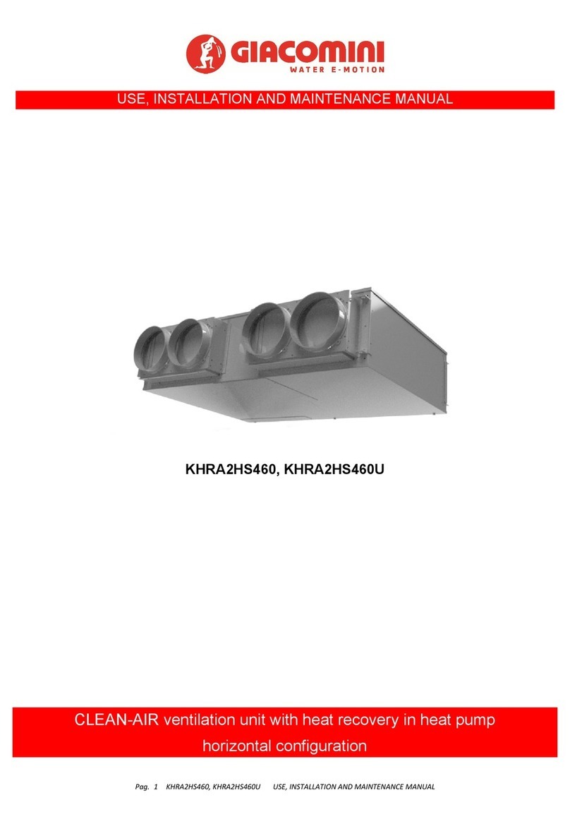
Giacomini CLEAN-AIR KHRA2HS460 Use, Installation and Maintenance Manual

