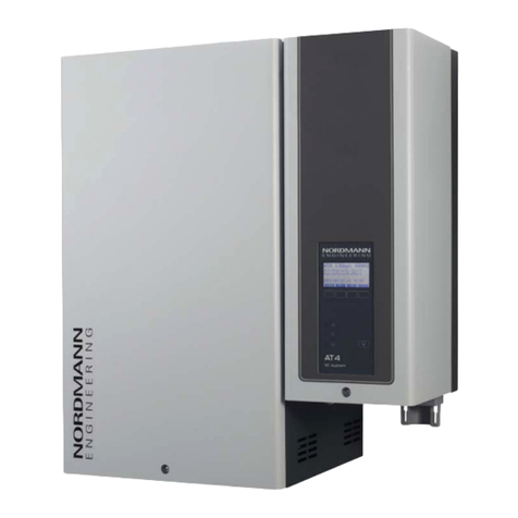
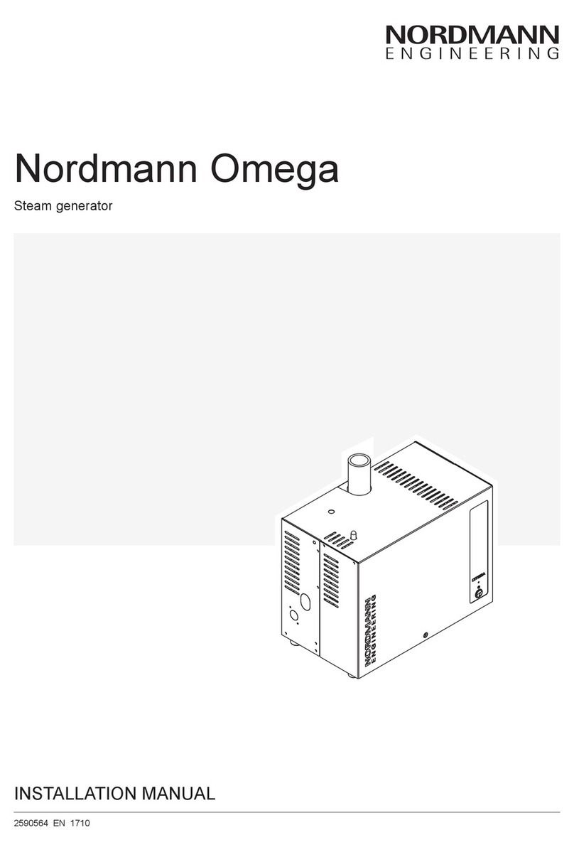
Nordmann Engineering Omega Series User manual

OPERATION MANUAL
Steam generator
Nordmann Omega
2590562-D EN 1901

Thank you for choosing Nordmann
Installation date (MM/DD/YYYY):
Commissioning date (MM/DD/YYYY):
Site:
Model:
Serial number:
Proprietary Notice
This document and the information disclosed herein are proprietary data of Nordmann Engineering AG. Neither
this document, nor the information contained herein shall be reproduced, used, or disclosed to others without the
written authorisation of Nordmann Engineering AG, except to the extent required for installation or maintenance
of recipient's equipment.
Liability Notice
Nordmann Engineering AG does not accept any liability due to incorrect installation or operation of the equipment
or due to the use of parts/components/equipment that are not authorised by Nordmann Engineering AG.
Copyright Notice
© Nordmann Engineering AG, All rights reserved.
Technical modications reserved.

3
Contents
1 Introduction 5
1.1 To the very beginning 5
1.2 Notes on the operation manual 5
2 For your safety 7
3 Product Overview 9
3.1 Models overview 9
3.2 Identicationoftheunit 10
3.3 ConstructionoftheNordmannOmegasteamgenerator 11
3.4 Functionaldescription 12
3.5 SystemoverviewNordmannOmega 13
4 Operation 14
4.1 First-timecommissioning 14
4.2 Display and operating elements 15
4.3 Commissioningafteraninterruptionofoperation 16
4.4 Notes on operation 17
4.5 Inspectionsduringoperation 17
4.6 Takingtheunitoutofoperation 18
5 Working with the SPA Display 19
5.1 Homescreens 19
5.1.1 Homescreens"Steamshowerapplication" 19
5.1.1.1 Homescreenswithactivated"Temperaturecontrol" 19
5.1.1.2 Homescreenswithoperationwith"constantsteamproduction" 20
5.1.1.3 Homescreenwithoperationwith"externalcontrol" 21
5.1.2 Homescreens "Steambathapplication" 22
5.1.3 Homescreens "Caldariumapplication" 23
5.1.4 Homescreens "Rasulapplication" 24
5.1.5 Homescreens "Finsaunaapplication" 25
5.2 Functionofthewarningtriangle 26
5.3 Navigationelements 26
5.4 Congurationofthecontrolsoftware 27
5.4.1 Accessingthemainmenu 27
6 CongurationofSPAcontrolsoftware 31
6.1 CongurationprocessesbasedontheSPAapplication 31
6.1.1 Congurationprocedureforsteamshowerapplication 31
6.1.2 Congurationprocedureforsteambathapplication 36
6.1.3 Congurationprocedureforsteambathapplicationwithoptionalbenchheating 38
6.1.4 CongurationprocedureforCaldariumapplication 40
6.1.5 Congurationprocedurefor Rasulapplication 42
6.1.6 Congurationprocedurefordualcabinapplicationsforsmallcabins 44
6.1.7 Congurationprocedurefordualcabinapplicationsformediumsizecabins 47
6.1.8 CongurationofseveralSPAdisplays 48
6.2 Settingsinthe"Service"menu 49
6.3 Settingsinthe"Engineering"menu 51

4
7 Maintenance 61
7.1 Importantnotesonmaintenance 61
7.2 Maintenanceintervals 62
7.3 Maintenancelist 64
7.4 Removingandinstallingcomponentsformaintenance 65
7.4.1 PreparingtheNordmannOmegafortheremovalofcomponents 65
7.4.2 Removalandinstallationofthesteamtank 65
7.4.3 Removalandinstallationofthellingcup,thelevelunitandthewaterhoses 70
7.4.4 Removalandinstallationofthedrainpump 72
7.4.5 Removalandinstallationoftheinletvalve 73
7.4.6 Removalandinstallationofthesteamtankreceptacle 74
7.5 Notesoncleaningtheunitcomponents 75
7.6 Notesoncleaningagents 77
7.7 Replacingtheoptionalltercartridge 78
7.8 Resettingthemaintenancecounter 80
8 Fault elimination 81
8.1 Importantnotesonfaultelimination 81
8.2 Faultindication 82
8.3 Malfunctionlist 83
8.4 Resettingthefaultindication 93
8.5 Replacingthefusesandbackupbatteryinthecontrolunit 94
9 Taking out of service/Disposal 96
9.1 Takingoutofservice 96
9.2 Disposal/Recycling 96
10 Productspecication 97
10.1 Performancedata/Fuses"F5"voltagesupply 97
10.2 Operatingdata 97
10.3 Connections/Dimensions/Weights 98
10.4 Certicates 98
11 Appendix 99
11.1 ProgramdescriptionsSPAapplications 99
11.1.1 Steamshowerapplication 99
11.1.2 Steambathapplication 99
11.1.3 Caldariumapplication 100
11.1.4 Rasulapplication 101
11.1.5 Finsaunaapplication 102

5
1.1 To the very beginning
We thank you for having purchased the Nordmann Omega steam generator.
The Nordmann Omega steam generator incorporates the latest technical advances and meets all rec-
ognized safety standards. Nevertheless, improper use of the Nordmann Omega steam generator may
result in danger to the user or third parties and/or damage to property.
To ensure a safe, proper, and economical operation of the Nordmann Omega steam generator, please
observe and comply with all information and safety instructions contained in the present documentation
as well as in the separate documentations of the components installed in the humidication system.
If you have questions after reading this documentation, please contact your Nordmann representative.
They will be glad to assist you.
1.2 Notes on the operation manual
Limitation
The subject of this operation manual is the Nordmann Omega steam generator in its different
versions. Options and accessories are only described insofar as this is necessary for proper operation
of the equipment. Further information on options and accessories can be obtained in the respective
instructions.
This operation manual is restricted to the commissioning, operation,maintenance and troubleshooting
of the Nordmann Omega steam generator and is meant for well trained personnel being sufciently
qualied for their respective work.
This operation manual is supplemented by various separate items of documentation (e.g. installation
manual, spare parts list, etc.), which are included in the delivery as well. Where necessary, appropriate
cross-references are made to these publications in the operation manual.
1 Introduction

6
Symbols used in this manual
CAUTION!
The catchword "CAUTION" used in conjunction with the caution symbol in the circle designates notes
in this operation manual that, if neglected, may cause damage and/or malfunction of the unit or
damage to property.
WARNING!
The catchword "WARNING" used in conjunction with the general caution symbol designates safety
and danger notes in this operation manual that, if neglected, may cause injury to persons.
DANGER!
The catchword "DANGER" used in conjunction with the general caution symbol designates safety and
danger notes in this operation manual that, if neglected, may lead to severe injury or even death
of persons.
Safekeeping
Please safeguard this operation manual in a safe place, where it can be immediately accessed. If the
equipment changes hands, the documentation must be passed on to the new operator.
If the documentation gets misplaced, please contact your Nordmann representative.
Language versions
This operation manual is available in other languages. Please contact your Nordmann representative
for information.

7
General
Every person working with the Nordmann Omega must have read and understood the Nordmann Omega
operation manual and installation manual before carrying out any work.
Knowing and understanding the contents of the operation manual and installation manual is a basic
requirement for protecting personnel against any kind of danger, to prevent faulty operation, and to
operate the Nordmann Omega safely and correctly.
All icons, signs and markings applied to the components of the Nordmann Omega must be observed
and kept in readable state.
Qualication of personnel
All work described in this operation manual may only be carried out by specialists who are well
trained and adequately qualied and are authorized by the customer.
For safety and warranty reasons any action beyond the scope of this manual must be carried out only
by qualied personnel authorised by Nordmann.
It is assumed that all persons working with the Nordmann Omega are familiar and comply with the ap-
propriate regulations on work safety and the prevention of accidents.
The Nordmann Omega steam generator may not be used by persons (including children) with reduced
physical, sensory or mental abilities or persons with lacking experience and/or knowledge.
Children must be supervised to make sure that they do not play with the Nordmann Omega steam
generator.
Intended use
The Nordmann Omega steam generator is intended exclusively for generation of steam for steam
shower, steam bath, Caldarium and Rasul applications within the specied operating conditions.
Any other type of application, without the written consent of Nordmann, is considered as not conforming
with the intended purpose and may lead to the Nordmann Omega becoming dangerous and will void
any warranty.
Operation of the equipment in the intended manner requires that all the information contained in this
operation manual are observed (in particular the safety instructions).
2 For your safety

8
Danger that may arise from the Nordmann Omega steam generator
DANGER!
Danger of electric hazard!
The Nordmann Omega is mains powered. Live parts may be exposed when the unit is open.
Touching live parts may cause severe injury or danger to life.
Prevention: Before carrying out any work set the Nordmann Omega out of operation as described in
chapter4.6 (switch off the unit, disconnect it from the mains and stop the water supply) and secure
the unit against inadvertent power-up.
WARNING!
Hot water vapour - Danger of scalding!
The Nordmann Omega produces hot water vapour. There is danger of scalding when coming
in contact with hot water vapour.
Prevention: Do not carry out any work on the steam system during operation (steam lines, steam
distributor, etc.). If the steam system is leaky set the Nordmann Omega immediately out of operation as
described in chapter4.6. Correctly seal the steam system before putting the unit into operation again.
WARNING!
Danger of burning!
During operation the components of the steam system (steam tank, steam distributor, etc.) get
very hot (up to 100 °C). There is danger of burning when touching the hot components.
Prevention: Before carrying out any work on the steam system set the Nordmann Omega out of
operation as described in chapter4.6, then wait until the components have cooled down sufciently
thus preventing danger of burning.
Preventing unsafe operation
If it is suspected that safe operation is no longer possible, the Nordmann Omega should immediately
be shut down and secured against accidental power-up according to chapter4.6. This can be the
case under the following circumstances:
– if the Nordmann Omega is damaged
– if the electrical installations are damaged
– if the Nordmann Omega is no longer operating correctly
– if connections and/or piping are not sealed
All persons working with the Nordmann Omega must report any alterations to the unit that may affect
safety to the owner without delay.
Prohibited modications to the unit
No modications must be undertaken on the Nordmann Omega without the express written consent
of Nordmann Engineering AG.
For the replacement of defective components use exclusively original accessories and spare parts
available from your Nordmann representative.

9
3.1 Models overview
Steam generators Nordmann Omega are available in two unit sizes with different heating voltages
and steam capacities ranging from 4 kg/h up to a maximum of 20 kg/h.
Model
Nordmann Omega
Unit size Max. steam capacity
in kg/h
PNmax.
in kW
Heating voltage
Small Medium
4 x 4 3.5 230 V/1~/50...60 Hz
8 x 8 6.5
8 x 8 6.5
400 V/3~/50...60 Hz
12 x 12 9.5
16 x 16 12.5
20 x 20 15.5
Key model designation
Example:
Nordmann Omega 8
Product designation:
Max. steam capacity in kg/h
3 Product Overview

10
3.2 Identicationoftheunit
The identication of the unit is found on the specication label:
Type designation Serial number (7 digits) Month/Year
Heating voltage
Maximum steam capacity per unit
Admissible water supply pressure
Power consumption heating
Field with certication symbols
Fig. 1: Locationofthespecicationlabel
Control voltage
Power consumption control voltage
Equipment variant
Nordmann Engineering AG, Talstrasse 35-37, 8808 Pfäfkon SZ, Switzerland
Type: Nordmann OMEGA 16 Serial No: XXXXXXX 10.18
Heating voltage: 400V/3~/50-60Hz Heating Power: 12.5 kW 26.6 A
Steam capacity: 16 kg/h Contr. voltage: 230 V/1~/50-60 Hz
Water press.: 100..1000kPa (1..10 bar) Control power: max. 3 kW 16A
Variant:
Bench Heating
Engineered in Switzerland, Made in Germany

11
1 Water supply connector G 3/4"
2 Inlet valve
3 Water supply hose
4 Drain pump
5 Water drain connector ø30 mm
6Water ll and drain hose
7 Level unit
8 Drain hose
9 Filling cup
10 Condensate connector ø10 mm (back to steam tank)
11 Condensate connector ø10 mm (to drain)
12 Steam outlet connector
ø30 mm (Small) / ø45 mm (Medium)
13 24 V power supply
14 Heating elements
15 Pressure equalizing hose
16 Steam tank
17 Coupling sleeve
18 Level hose
19 Pump hose
20 Manual drain hose
21 Unit switch
22 Status LED
23 Reset button maintenance counter
24 Specication label
25 Omega or SPA control board
26 Terminals voltage supply ("L1", "L2", "L3" and "PE")
27 Heating contactor
28 Terminals voltage supply ("N")
29 Over temperature switches
30 SPA Display (option)
Fig. 2: ConstructionNordmannOmegasteamgenerator(gureshowsmediumsizedunit)
3.3 Construction of the Nordmann Omega steam generator
1
2
3
6
4
5
7
9
11
12
10
8
20
19
18
13
15
14
25
27
26
28
13
21
30
17
16
24
29
23
22

12
3.4 Functional description
The Nordmann Omega steam generator is an atmospheric steam generator. It operates on the resist-
ance heating principle and is designed for steam generation for steam shower, steam bath, Caladarium
and Rasul applications.
Water supply
The water is supplied via a lter valve (accessory "Z261") to the steam generator. It reaches the steam
tank via the level controlled inlet valve and the open lling cup.
Note: The open lling cup is designed in such a way, that the supply water is separated from the unit
water. That means, that no unit water can ow back into the supply water line.
Level regulation
The water level in the steam tank is continuously monitored with the level unit. If the water level reaches
a preset level (due to the evaporation process) the level unit supplies a signal to the controller. This
opens the inlet valve and the steam tank is lled up. When the preset operating level is reached, the
level unit supplies another signal to the controller to close the inlet valve.
The pressure equalizing pipe connected to steam tank and the level unit ensures that the water levels
are the same in the steam tank and the level unit.
Steam generation regulation
The steam is produced in the steam tank by one or several resistance heating elements. The integrated
continuous controller or an external controller control the steam production in steps from 0 to 100 %.
Alternatively the Nordmann Omega can be controlled also via an On/Off controller.
Flushing
The evaporation process increases the concentration of minerals in the water of the steam tank.Asuitable
volume of water must be ushed out of the steam tank from time to time and replaced by fresh water to
ensure that this concentration does not exceed a specic value unsuitable for operation.
The Nordmann Omega consists of the following two forms of ushing:
– Automatic ushing takes place as soon as the water in the steam tank exceeds the upper operat-
ing level (e.g. by foaming of the water).
– Flushing dependent on water quality.
Automatic or water quality dependent ushing takes place depending on the water quality and the op-
erating data. If the lowest operating level is reached during the ushing process, the inlet valve remains
open until the water level in the steam tank has reached the normal working level again. If the lowest
operating level is not reached, the inlet valve is closed.

13
3.5 System overview Nordmann Omega
1 Steam generator
2 Steam outlet connector
ø30 mm (Small) / ø45 mm (Medium)
3 Condensate connector ø10 mm (to drain)
4Condensate connector ø10 mm (back to steam tank)
5 Water drain connector ø30 mm
6 Water supply connector G 3/4"
8 Water supply line (by others)
8 Manometer (recommended, by others)
9Filter valve (accessory "Z261")
10 Filter cartridge (option "Size S" or "Size L")
11 Drain hose (by others)
12 Open funnel with water trap (by others)
13 Electrical isolator voltage supply
14 Steam hose(accessory "DS60" or "DS80")
15 Steam distributor
16 Temperature sensor
Fig. 3: SystemoverviewNordmannOmega
Inner diameter
30 mm (Small) / 45 mm (Medium)
3
2
4
5
6
7
9
8
Z261
12
11
10
14
15
16
13
1

14
The Nordmann Omega steam generator may be commissioned and operated only by persons familiar
with the Nordmann Omega steam generator and adequately qualied. It is the owner’s responsibility to
verify proper qualication of the personnel.
4.1 First-time commissioning
The rst-time commissioning must always be done by a service technician of your Nordmann repre-
sentative or a well trained and authorised person of the customer. Therefore the current manual does
not provide detailed information on this procedure.
The following steps are carried out upon rst-time commissioning in the specied order:
• Inspecting the steam generator for correct installation.
• Inspecting the electrical installation
• Inspecting the water installation
• Inspecting the steam installation
• Flushing and deaerating the water supply line
• Determining the carbonate hardness of the supply water (by measurement or from the local water
supplier)
• Conguring the control software of the Nordmann Omega via the integrated web interface (see
separate web interface operation manual) or the SPA Display (see chapter6.1).
• Carrying out test runs including checking of the control and monitoring devices.
• Filling out the commissioning record.
4 Operation

15
4.2 Display and operating elements
External electrical isolator(s) for voltage supply/supplies (not
included in the delivery, must be installed in the mains supply lines)
SPA Display (option)
Reset button maintenance counter
(only on units without optional SPA Display)
Status LED
– green: Nordmann Omega is humidifying
– green pulsing: Nordmann Omega is in standby operation
– yellow: Warning present or maintenance due
– red: Fault present
Unit switch
Fig. 4: Display and operating elements
DANGER!
Risk of electric shock!
After switching off the unit switch, there is still live voltage inside the control compartment of the Nord-
mann Omega. Therefore, before opening the unit the steam generator must be always separated
from the mains supply/supplies via the electrical isolator(s).
CAUTION!
If the Nordmann Omega controls a sauna heater, it must be ensured that the sauna heater is
equipped with a approved safety system (e.g. cover protection) to avoid switching on in an in-
secure condition (e.g. towel on a sauna heater). See Nordmann Omega installation instructions.
Otherwise, it is not permitted to use remote control devices which controls and regulates a
device by means of a command that can be made outside the range of vision of the controlled
device (SPA display, KNX, Modbus, web interface, etc.). This includes the timer functions as well.

16
4.3 Commissioning after an interruption of operation
The following description outlines the start up procedure after an interruption of operation (e.g. after
servicing the steam generator). It is assumed that rst-time commissioning has been carried out prop-
erly by the service technician of your Nordmann representative and the Nordmann Omega has been
congured accordingly.
1. When putting the steam generator into operation after work has been carried out on the steam sys-
tem, the operating personnel must check whether the steam pipe is open over the entire length.
WARNING!
Danger of scalding!
A steam line that is reduced in cross section or completely closed will cause an excessive
increase in pressure in the steam tank when the unit is operating and could lead to the risk
of scalding accidents!
2. Examine the steam generator and installation for possible damage.
DANGER!
A damaged unit or systems with damaged installations may present danger to human life
or cause severe damage to material assets.
Therefore: Damaged systems and/or systems with damaged or faulty installations must not be
operated.
3. Relocate the unit cover and lock it with the retaining screw.
4. Open the lter valve / shut-off valve in the water supply line.
5. Switch on the electrical isolator(s) in the mains supply line(s).
6. Switch on the unit switch of the steam generator.
The Nordmann Omega carries out an automatic system test (initialising). If a malfunction is detected
during the system test, the status LED indicates a "Warning" (LED lights yellow) or "Fault" (LED
lights red).
If the is successful, the steam tank lls up and a function check on the level unit is carried out.
Note: If a malfunction is detected during the function check on the level unit, the status LED indicates
a "Warning" (LED light yellow) or "Fault" (LED light red).
If the function check on the level unit is successful, the Nordmann Omega will be in normal op-
erating mode and the LED blinks green. As soon as a steam demand is present or the bathing
operation is started manually, the heating current is switched on, the status LED lights green and
steam is produced after a short time.

17
4.4 Notes on operation
After 24 hours in standby operation (no humidity demand), the steam tank is emptied automatically. The
steam tank remains empty and is not lled until a steam demand is present or the bathing operation is
started manually.
If, during operation, it is recognized that consistently foaming occurs in the steam tank, the carbonate
hardness setting of the inlet water should be increased. As a result, the steam tank of the Nordmann
Omega is drained more frequently and thus the foam formation is counteracted.
4.5 Inspections during operation
During operation the Nordmann Omega and the humidication system have to be inspected weekly. On
this occasion check the following:
• the water and steam installations for any leaks.
• the steam generator and the other system components for correct xing and any damage.
• the electric installation for any damage.
If the inspection reveals any irregularities (e.g. leakages, error indication) or any damaged components
take the Nordmann Omega out of operation as described in chapter4.6. Then, contact your Nordmann
representative.

18
4.6 Taking the unit out of operation
In order to take the Nordmann Omega steam generator out of operation (e.g. for maintenance purpose),
perform the following steps:
1. If maintenance work on the water system of the Nordmann Omega is to be carried out, the steam
tank must be emptied. Proceed as follows:
a. Switch off the Nordmann Omega via the unit switch.
b. Wait 5 seconds, then switch the Nordmann Omega on again. If the drain pump starts, wait 60
seconds (with the Omega Medium 100 seconds) until the steam tank has been emptied. If the
drain pump does not start automatically within 10 seconds (e.g. because of a pump failure), drain
the steam tank manually via the manual drain hose (see step 5).
2. Close the shut-off valve in the water supply line.
3. Switch off the Nordmann Omega via the unit switch (if not yet switched off).
4. Disconnect Nordmann Omega from the mains: Switch off the electrical isolator(s) in the mains
supply line(s) and secure switch(es) in "Off" position against accidentally being switched on, or
clearly mark the switch.
5. If you have to carry out work on the water system: Loosen the retaining screw on the unit cover,
remove the unit cover, then drain (residual) water from the steam tank into an empty bucket via the
manual drain hose (position of the drain hose, see Fig. 2).
WARNING!
Danger of burning!
The water in the steam tank can be hot (up to 95 °C). There is danger of burning when
draining the steam tank via the manual drain hose shortly after steam has been produced.
Prevention: wear isolating gloves and be careful when draining the water via the manual drain hose.

19
5.1 Home screens
After switching on the Nordmann Omega and the automatic system test the steam generator is in normal
operating mode and the Home screen is shown. The appearance of the Home screen depends on the
conguration of the control software.
5.1.1 Home screens "Steam shower application"
5.1.1.1 Home screens with activated "Temperature control"
Timer functions disabled or Start option set to manual.
Warning triangle (function see chapter5.2)
Navigation elements (see chapter5.3)
Selected SPA application
Note: With dual cabin application, you can toggle between the two applications
by pressing on the SPA application eld.
Current temperature in the steam cabin in °C/°F.
Note: By pressing this button you access the settings window for determining
the temperature setpoint value.
<START>/<STOP> button
Note: By pressing the <START> button you start the bathing operation, the
button changes to <STOP>. By pressing the <STOP> button you can stop
the bathing operation at any time.
Note: After the start of the bathing operation with the <START> button, an ad-
ditional eld appears above the <START>/<STOP> eld with the clock symbol
showing the remaining time until the end of bathing operation.
This eld does not appear if the Start option is set to "Manual", as no bathing
time (session time) can be set if manual start mode is activated. The bathing
operation must be stopped with the <STOP> button.
25.0 °C
Steam Shower
START
5 Working with the SPA Display

20
Timer-controlled steam shower operation, the steam shower operation starts at the preset starting time
or after pressing the <START> button.
20.0 °C
Mo 10:00
START
Steam Shower
Warning triangle (function see chapter5.2)
Navigation elements (see chapter5.3)
Selected SPA application
Note: With dual cabin application, you can toggle between the two applications
by pressing on the SPA application eld.
Current temperature in the steam cabin in °C/°F.
Note: By pressing this button you access the settings window for determining
the temperature setpoint value.
<START>/<STOP> button
Note: By pressing the <START> button you start the bathing operation, the
button changes to <STOP>. By pressing the <STOP> button you can stop
the bathing operation at any time.
Set starting time (weekday/time of day) with timer controlled bathing operation
or "Off" if no timer has been set.
Note: By pressing this button you access the timer settings window for deter-
mining the day timer and/or week timer settings.
Note:After having started the steam bath operation (via <START> button or via
timer) the remaining time until the end of the steam bath operation is displayed.
5.1.1.2 Homescreens with operation with "constant steam production"
Timer functions disabled or Start option set to manual.
Warning triangle (function see chapter5.2)
Navigation elements (see chapter5.3)
Selected SPA application
Note: With dual cabin application, you can toggle between the two applications
by pressing on the SPA application eld.
Current steam production in % of the maximum steam capacity
Note: By pressing this button you access the settings window where you can
set the steam production to "Low", "Mid" or "High".
<START>/<STOP> button
Note: By pressing the <START> button you start the bathing operation, the
button changes to <STOP>. By pressing the <STOP> button you can stop
the bathing operation at any time.
Note: After the start of the bathing operation with the <START> button, an ad-
ditional eld appears above the <START>/<STOP> eld with the clock symbol
showing the remaining time until the end of bathing operation.
This eld does not appear if the Start option is set to "Manual", as no bathing
time (session time) can be set if manual start mode is activated. The bathing
operation must be stopped with the <STOP> button.
0.0 %
Steam Shower
START
This manual suits for next models
5
Table of contents
Other Nordmann Engineering Iron manuals
