NORDOCK ASG User manual
Owner’s Manual and Parts List
This manual applies to safety gates manufactured for Sales
Order SO56717, April 2021, with Serial numbers 55350 - 55352
P/N: 56717-OM
N
ORDOCK INC.
Website: Nordockinc.com ~ Email: Sales@Nordockinc.com ~ Toll ree: 866-885-4276
Nordock Inc. reserves the right to make changes to specifications without notice or obligation. Nordock products may be covered by
various U.S. and foreign patents or pending applications.
Sa ety Gate
Model “ASG”

Nordock Inc. Parts and Service Manual 56717-OM, ASG1010 Powered Sa ety Gate
- 1 -
Table o Contents
Table o Contents ................................................................................. 1
Pre ace ............................................................................................... 2
Problems, Errors and Omissions ................................................................................. 2
Product Identification ................................................................................................... 2
Copyright ..................................................................................................................... 2
Warranty ............................................................................................. 3
Sa ety ................................................................................................. 4
Installation .......................................................................................... 5
General Notes.............................................................................................................. 5
Assembly Instructions.................................................................................................. 7
Column Mounting Instructions ..................................................................................... 9
Counterweight Installation Instructions ...................................................................... 11
Barrier Mounting Instructions....................................................................................... 9
Electrical Installation.................................................................................................. 13
Smart Gate Setup Procedure .................................................................................... 13
Operation .......................................................................................... 14
Standard Operation ................................................................................................... 14
Maintenance and Lubrication ............................................................... 15
Parts List ........................................................................................... 16
Electrical Schematic ............................................................................ 18

Nordock Inc. Parts and Service Manual 56717-OM, ASG1010 Powered Sa ety Gate
- 2 -
Pre ace
PLEASE READ AND UNDERSTAND THIS MANUAL COMPLETELY
This manual gives detailed information and instruction on how to operate and
maintain your equipment correctly. Failure to do so could result in personal injury,
and/or equipment damage. Please consider this manual a permanent part of the unit
and keep it with the safety gate for reference whenever needed.
If you have any questions about this manual, the safety gate, its components, or
our products and services, please call us at 1-866-885-4276 and we will be happy to
assist you. With proper care and maintenance, this safety gate is designed to work
effectively and efficiently for many years to come.
Problems, Errors and Omissions
This manual has been prepared with the utmost care and attention to detail as to
ensure accurate parts and service information should the need arise. Nordock
Incorporated believes this manual will provide the operators of this unit all the necessary
information required to operate and maintain it for many years. If you believe there is
an error, if you have a problem following the guidelines, or if there is information that
you feel is missing from this manual, please contact us at the above number so we may
attend to the issue immediately.
Product Identi ication
It is very important that in order to obtain the best possible service from Nordock Inc.,
please include the model and serial number of the safety gate whenever you contact us.
Below is the same serial number decal that will be found on the front of the movable
barrier. Please fill in the information from the decal on the safety gate in this area. This
will greatly reduce the possibility of improper parts being shipped to you.
Copyright
This manual is copyright to Nordock Incorporated. All information, text, drawings, and
technical data contained herein are for reference only. No part of this manual may be
copied, altered, or stored on electronic media, and cannot be revealed to others for the
purpose of competition.
DES
CRI
PTION
R
SE
RIAL #:
866
-
885
-
4276 ~ WWW.NORDOCKI
NC.COM
MADE IN CANADA
XX X
X XX000 LBS
XXXX

Nordock Inc. Parts and Service Manual 56717-OM, ASG1010 Powered Sa ety Gate
- 3 -
Warranty
Nordock Inc. expressly warrants that all of its manufactured product shall remain free of
defects in material and workmanship under normal use for a period of one-year from the
date of delivery to the purchaser. The purchaser must maintain and operate the product
in accordance with proper procedures. In the event the product proves defective in
material or workmanship, Nordock Inc. will at its option either:
1. Replace the product or the defective portion thereof without charge to the
purchaser; or,
2. Alter or repair the product on site or elsewhere, as Nordock Inc. may deem
advisable, without charge to the purchaser.
The warranty stated herein is that offered by Nordock Inc. and expressly disclaims all
implied warranties including those of merchantability and fitness. This warranty does not
cover any failure caused by improper installation, misapplication, overloading, abuse,
negligence, or failure to maintain and protect the equipment from vehicle impact.
Nordock Inc. or its representative assume no responsibility or liability for any incidental
or consequential damages of any kind including loss of use of any equipment, damage
or failure resulting from the use of unauthorized replacement parts or equipment
modification, or damages resulting from the misuse of the equipment.
Nordock Inc. warranties extend only to the product itself. Nordock Inc. disclaims all
liability of any kind arising out of the workmanship, methods and materials used by the
installer or premature product wear, product failure, property damage or bodily injury
arising from improper installation.
These warranties as stated herein are the exclusive remedies for all claims.

Nordock Inc. Parts and Service Manual 56717-OM, ASG1010 Powered Sa ety Gate
- 4 -
Sa ety
The operators of this unit must read these safety practices before installing, operating or
servicing the safety gate. Failure to follow these safety practices may result in bodily
injury, property damage or death.
Read and follow the operating instructions contained in this manual before
operating the safety gate. If you do not understand the instructions, contact your
supervisor for explanation and instruction on the safe operation of this unit. The
following guidelines are to be used in conjunction with all laws, governances, and
codes in effect where the safety gate is installed.
1. Inspect the safety gate to ensure that all parts are undamaged and in good
working order. If the safety gate does not appear to function properly, or if it
looks damaged, DO NOT USE THE SAFETY GATE. Section off the gate area
and notify your supervisor and safety representative.
2. Do not sit on the barrier or place objects or equipment on it. The lifting and
support system is designed to support the weight of the barrier only. The barrier
may suddenly collapse without warning if additional weight is placed upon it.
3. Do not stand under the safety barrier when it is in motion.
4. Do not attempt to ride on the safety barrier.
5. Never use a fork truck or any type of material handling equipment to raise or
lower the barrier.
6. Keep hands and all body parts always clear of the barrier. If the safety gate fails
to operate using the procedures contained in this manual, do not use the safety
gate. Contact Nordock Incorporated or an authorized service representative for
service.
7. Whenever any maintenance or repair is to be performed on the safety gate,
Barricade the area around the barrier and place clear signage on the perimeter
that the unit is not to be operated.
8. If you have any questions, contact your supervisor or your local Nordock
Incorporated representative.
!
WARNI
NG
Nordock Inc. Parts and Service Manual 56717-OM, ASG1010 Powered Sa ety Gate
- 5 -
Installation
General Notes
The gate may be assembled and installed in one of two ways:
1. Assemble all stationary gate components together flat on the floor and tilt up to the
vertical position.
2. Tilt each column up separately and assemble the components in the upright
position.
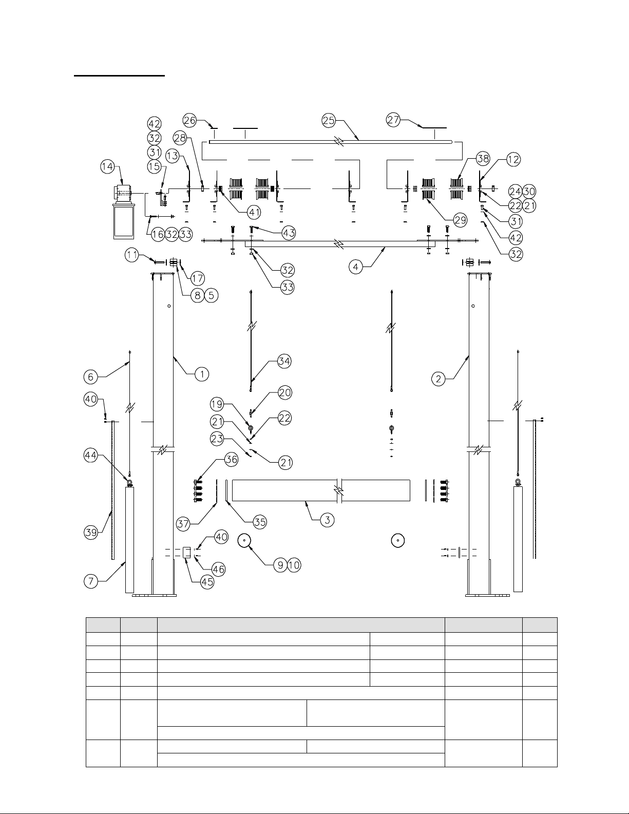
The order of assembly is the same whether assembling the unit on the floor or in the
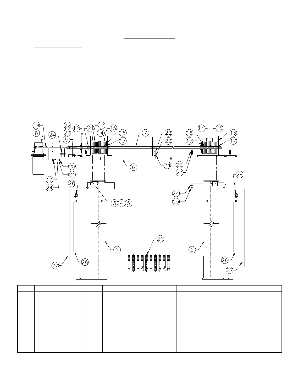
upright position. Refer to the drawing and parts list below when assembling the unit.
ITEM DESCRIPTION QTY ITEM DESCRIPTION QTY ITEM DESCRIPTION QTY
1
COLUMN, LEFT
1
1
1
21
COLLAR
2
2 COLUMN, RIGHT 1 12 SHAFT PIVOT, L 3 22
BOLT, 3/8” x 1-1/2” 24
3
C
A
BLE ROLLER
2
1
3
SHAFT PIVOT, R
3
2
3
LOCKW
ASHER, 3/8”
12
4
BUSHING
4
1
4
DRUM,
L
EFT
2
24
FLATWASHER, 3/8”
36
5 ROLLER PIN 2 15 DRUM, RIGHT 2 25
NYLOCK, 3/8” 12
6
SPREADER CHANNEL
1
1
6
KEY,
6
”
2
26
COUNTERWEIGHT
2
7
TORQUE SHAFT
1
1
7
DRUM SPACER
A/R
27
C
T
RWGHT COVER PL
AT
E
(S)
2
8 OPERATOR c/wTARM 1 18 28
SHACKLE, ¼” 2
9
T.ARM
M
TG
BRKT
1
1
9
KEY,
2 3/8
”
1
29
ANCHOR,
3/4
” x 6”
(B
y others)
10
10 BOLT, 3/8”x 2-1/2” 3 20
Nordock Inc. Parts and Service Manual 56717-OM, ASG1010 Powered Sa ety Gate
- 6 -
R
L
L
L
R
R
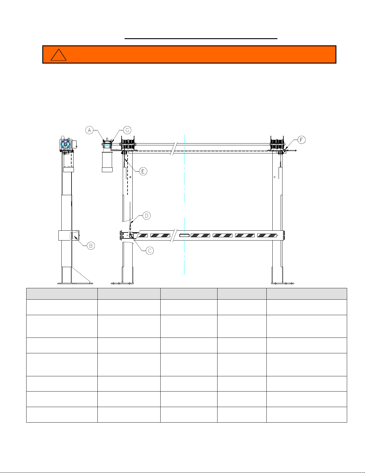
NOTE: Barrier and Cables are not shown in drawing above.
To ensure correct operation of the safety gate, it is critical that the two vertical side
columns (1 & 2) are installed plumb and parallel to one another in both vertical planes.
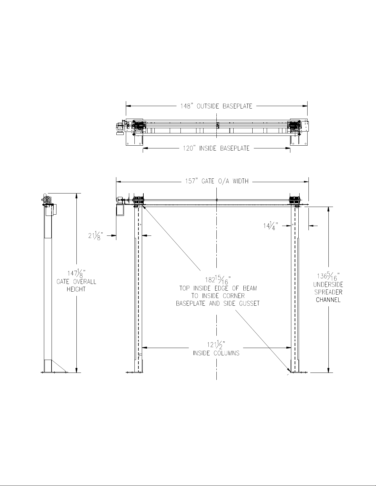
The drawing below shows several reference dimensions, which will aid during the
installation process.
DIMENSIONS – 10’ (120”) WIDE x 10’ (120”) HIGH GATE:
Note:
Left hand (LH) gate shown.

Nordock Inc. Parts and Service Manual 56717-OM, ASG1010 Powered Sa ety Gate
- 7 -
Assembly Instructions
For ease of installation, the spreader channel assembly has all components except the
cables shipped factory assembled. Refer to the installation parts diagram and table
starting on page 5 as needed.
Numbers in parenthesis refer to Items listed in chart on page 5.
1. Place the left and right vertical upright columns (1&2) parallel to one another at the
Inside Column dimension as shown in the diagrams on the preceding page(s).
2. Determine the correct operator handing for the gate being built. Place the torque
shaft (7) end with the operator on the side of the gate to suit the handing required.
See also gate dimension drawings starting on page 6.
3. Check over the spreader channel (6) and components (7 to 21) for no obvious signs
of movement or damage during shipping. Brackets, operator, torque arm and shaft
should be square and parallel to the bottom plate and cross-channel.
4. The torque shaft (7) requires a dimension of 1-3/8” be maintained over the length of
the cross-channel. The shaft will need to be realigned if this dimension has changed.
See diagram below.
To re-align shaft and components:
a. Loosen the pivot bracket bolts (22) and shift the brackets (12 &13) forward or
back to obtain 1-3/8”.
b. Securely re-tighten the pivot bracket bolts across the spreader channel.
c. Check that the operator (8) is aligned vertically.
d. Verify that the shaft is straight.
The end of the spreader channel with the operator goes to the left-hand side of the gate (as
viewed standing on the dock looking out the door) for a left-hand operated gate.
NOTE
NOTE
L
R
L

Nordock Inc. Parts and Service Manual 56717-OM, ASG1010 Powered Sa ety Gate
- 8 -
5. Bolt the spreader channel/torque shaft assembly to the top of the upright columns,
using the eight 3/8” x 1-1/2” long bolts (22) and fasteners (23, 24 & 25) provided. Each
connection should have a 3/8” washer (24) on the top and a 3/8” washer (24) with a
nylock nut (25) on the bottom. See picture.
6. Finish tightening the bolts that hold the spreader channel to the columns.
7. The partially assembled gate is now ready to be raised to the vertical position if steps 1
to 6 have been completed with the gate on the floor.
Cables are not installed on the drums for shipping purposes. For installation ease it may
be convenient to attach them now to the corresponding drum. The drums in line with the
inner I beam are used for the barrier gate. The drums in line with the outer I beam are
used for the counterweights. Cables are marked accordingly.
NOTE

Nordock Inc. Parts and Service Manual 56717-OM, ASG1010 Powered Sa ety Gate
- 9 -
Column Mounting Instructions
If the gate was partially assembled flat on the ground, it must now be tilted to the vertical
upright position.
Columns (1&2) are shipped with the roller (3 to 5) for the counterweight cable factory
assembled.
When tilting the gate, do not use the torque shaft or the spreader channel as a lifting
point. They are not designed for this purpose and will bend. Any lifting must be
done at the top of the columns.
1. The gate is to be centred in the door opening and positioned far enough away from
the door to allow adequate clearance between the movable barrier and the door.
2. Before setting any anchors (29), ensure both columns are square and plumb. Refer
to the drawing starting on page 6 for reference dimensions.
Floors must be a minimum of 6” thick concrete to use the supplied anchors.
The minimum embedment depth for a 1” wedge anchor is 4-1/2” (a customer using
3/4” epoxy set anchors, depth by manufacturer specification).
3. Drill and set one anchor (29) in the base plate of each column, but do not tighten.
4. Check to ensure the columns are square and plumb again and adjust if necessary.
Drill and set the remaining four anchors in each plate and torque all anchors to
manufacturer specification to achieve maximum holding strength.
Barrier Mounting Instructions
1. Remove the counterweights access cover plates (27) from each side of columns.
2. Remove the end plates from both ends of the barrier assembly. Tilt the barrier at an
angle and position it between the columns.
There is a left and right end to the gate assembly. The eyebolt at each end should be
pointing up and will be in line with the barrier cable, once installed. The eyebolt goes in
the outer of the two holes in the mounting angle as shown below.
NOTE
!
WARNING
NOTE
NOTE
Nordock Inc. Parts and Service Manual 56717-OM, ASG1010 Powered Sa ety Gate
- 10 -
3. Using a forklift or other suitable lifting device, lift the gate up between the columns.
Insert 1/2" rods (by others), through the 13/16” diameter holes provided near the top
of both left and right column beam flanges. This will support the gate while the
cables are being attached.
4.
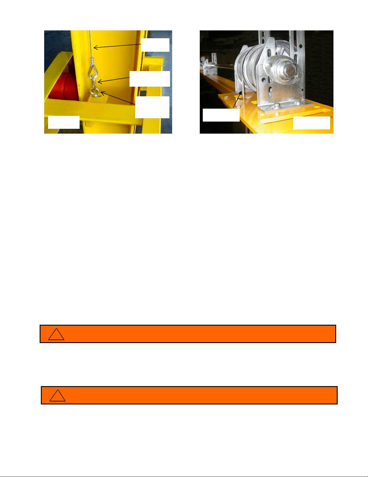
Install the barrier gate cables:
a. Hook cable stop into drum and wind snug until matching the barrier.
b. Maintain tension on the cable and clamp it to the frame with light spring clamp to
hold it snug on drum.
c. Connect the cable and eyebolt with 1/4” diameter quick link provided.
d. Repeat on opposite end.
e. Use 3/8” drive in fan end of operator to take up any cable slack as spring clamps
are removed.
f. Now cables are taught with barrier at raised position.
Do not attempt to use operator alone to raise or support the barrier. Personal injury
may result. Counterweights must first be installed.
5. Check all connections before proceeding to next step.
When connecting the barrier, always make sure there are several threads on the
eyebolt protruding past the nuts on the bottom side of the angle. A nylock nut or
a lock washer must be used under the nut on the eyebolts to prevent them from
loosening.
QUICK LINK
CONNECTOR
EYEBOLT,
FACTORY
INSTALLED
BARRIER
CABLE
LEFT SIDE
SHOWN
BARRIER
CABL
E
RIGHT SIDE
SHOWN
!
WARNING
!
WARNING

Nordock Inc. Parts and Service Manual 56717-OM, ASG1010 Powered Sa ety Gate
- 11 -
Counterweight Installation Instructions
1. 1/2” support rods are still holding barrier in raised position.
2. Place a temporary spacer block, by others, (approx. 2” high) in bottom pocket of each
beam. This block is used to raise the counterweight up high enough to allow the cable
to be attached.
Each counterweight weighs at least 106lbs. Exercise appropriate caution when
handling so as not to pinch, crush or strain any part of the body.
3. Place a counterweight (26) so that it fits inside the column, with the cable connection
bracket pointing up.
4. Hook cable stop into drum and wind cable snug until matching counterweight when
wrapped over roller and centered with column.
5. Maintain tension on cable to keep aligned in the drum grooves and connect cable to
weight with shackle.
6. Tilt the counterweight outwards to take up the slack in cable.
7. Remove spacer block and allow weight to swing into place.
8. Repeat Step 3 for the other side of the gate.
!
WAR
NING
GATE
FRONT
COUNTER
WEIGHT CABLE
COUNTER
WEIGHT
ROLLER
RIGHT SIDE
SHOWN
SHACKLE

Nordock Inc. Parts and Service Manual 56717-OM, ASG1010 Powered Sa ety Gate
- 12 -
•The number of cable wraps on the drum will vary with gate height and width.
•After temporary blocks are removed, the counterweight should not bottom out
before barrier is to the top of its travel.
•It is very important that the torque shaft not be rotated until after all four cables
are connected to the gate and counterweights.
9. Ensure free movement of the cable at both rollers (3) and shackle ends (28).
10.Check all 4 drums (14, 15) to verify that the cables are all seated properly in the
drum grooves. Correct, as necessary.
11.Use 3/8” drive in the operator to raise the barrier gate and remove the 1/2" rods used
to support the barrier prior to all cables and counterweights being installed.
12. Re-install the two barrier end plates with 3/4" bolt provided (4 on each side).
13. Check the barrier for level in both directions and adjust the eyebolts if necessary.
14. Install the access counterweight cover plates (27) that were previously removed.
Underside of Barrier to Finished Floor dimensions:
GATE HEIGHT RAISED LOWERED
8’ 98”
27”
8.5’
104”
9’ 110”
9
.5’
11
6
”
10’ 122”
10.5
’
128
”
The mechanical install is now complete. Proceed with the electrical installation in
the next section.
NOTE
S

Nordock Inc. Parts and Service Manual 56717-OM, ASG1010 Powered Sa ety Gate
- 13 -
Electrical Installation
a. Mount the push button station in a convenient location with an unobstructed view of
the gate and the area around it.
b. Wire the incoming power and all connections into the appropriate terminals at the
gate mounted operator. See separate wiring diagram or back page of this manual.
c. Test gate function by operating gate up and down. The gate should stop
automatically at the upper travel limit.
d. The gate has been tested at Nordock. However, the bottom limit may need
recalibration for any drum/cable changes. See setup procedure below.
Smart Gate Setup Procedure
1. Turn power on.
2. If vehicle restraint is not fully released, press RELEASE button first.
3. Engage vehicle restraint first by pressing LOCK button.
4. Press BYPASS button to silence the alarm and override the restraint.
5. Press and hold "OK" button located on door control board (bottom board inside the
panel). Wait until the message 'Setup Menu' appears, then release the button.
6. Push button labeled OPEN on front panel. If you observe the gate moving up
(opening), wait until the gate fully opens and it stops by itself. If the gate is closing
when you press OPEN button, turn the power off and interchange M1 and M2 gate
motor wires.
Please note that the STOP push button does not work during the setup procedure.
You must turn the power off to stop the door. Repeat sequence from Step 1.
7. Press and hold CLOSE button until the gate reaches the lowest point. If you go to
low, you can use the OPEN button to raise the gate. When you reach optimum
closing position press STOP button.
8. The setup is complete.
9. Push OPEN button to open the gate fast. The gate will slow down just before
reaching the fully open position and will stop when fully open. If STOP button is
depressed, the gate will stop but the dock will not operate unless is fully open.
10. Push and hold CLOSE button to close gate. The gate will close at approximately half
of opening speed and slow down just before closing limit. The gate must be fully
closed to enable vehicle restraint.
!
WARNING

Nordock Inc. Parts and Service Manual 56717-OM, ASG1010 Powered Sa ety Gate
- 14 -
Operation
Before operating or maintaining the safety gate, read and follow the safety practices
contained in this manual. Failure to follow the guidelines in this manual and those
in effect in the workplace can result in serious bodily harm and equipment damage.
Standard Operation
A three button (“OPEN-CLOSE-STOP”) pushbutton station is supplied standard with
the safety gate.
1. Hitch truck using the procedures on the control panel.
2. TO RAISE THE GATE: Press and release the “OPEN” pushbutton. The gate
will raise and stop automatically when it reaches the upper limit. The gate may
be stopped at any point in its upward travel by pressing and releasing the
“STOP” pushbutton.
3. TO LOWER THE GATE: Press and hold the “CLOSE” pushbutton. The gate
will lower until it reaches the lower limit. The gate will also stop its downward
travel if the “CLOSE” pushbutton is released prior to the gate reaching its lower
limit.
!
WARNING
Nordock Inc. Parts and Service Manual 56717-OM, ASG1010 Powered Sa ety Gate
- 15 -
ORDOCK
N
Maintenance and Lubrication
Before operating or maintaining the safety gate, read and follow the safety practices
contained in this manual. Failure to follow the guidelines in this manual and those in effect
in the workplace can result in serious bodily harm and equipment damage.
Note:
Use only the lubricant grades specified in this manual. Failure to use the
materials listed may lead to premature failure and will void any warranty claims for the
safety gate.
Item Lubrication Adjustment Cleaning Inspection
- A -
Door Operator
None None None
Required
To check for notice on
screen annually
- B -
Shock Absorber
None None None
Required
Every 6 months check
for damaged or missing
rubber
- C -
Barrier Cable
None None None
Required
Every 30 days, check
both cables for fraying
- D -
Shock Absorber
None None None
Required
Every 6 months check
for damaged or missing
rubber
-E-
Counterweight Cable
None None None
Required
Every 30 days, check
both cables for fraying
-F-
All Fasteners
None None None
Required
Every 6 months, check &
tighten as required
-G-
Sprockets & Collars
None None None
Required
Every 3 months, check
set screw tightness
!
WARNING
Nordock Inc. Parts and Service Manual 56717-OM, ASG1010 Powered Sa ety Gate
- 16 -
Parts List
Item
Qty. Description / Model P/N Note
1 1 UPRIGHT COLUMN, LEFT, Special 10’ HIGH 52-0510
2 1 UPRIGHT COLUMN, RIGHT, Special 10’ HIGH 520513
3 1 BARRIER ASSEMBLY 10’ WIDE 52-0519
4 1 SPREADER CHANNEL, SPECIAL 10’ WIDE 52-0546
5 2 ROLLER, CABLE COUNTERWEIGHT 53-0516
6 2 CABLE ASSEMBLY,
COUNTERWEIGHT
10’(120”) x 10’(120”)
52-0531-10-
10
Gate Width & Height must be specified when ordering
7 2 COUNTERWEIGHT 120” WIDE 52-0532
Gate Width & Height must be specified when ordering

Nordock Inc. Parts and Service Manual 56717-OM, ASG1010 Powered Sa ety Gate
- 17 -
Item
Qty. Description / Model P/N Note
8 4 BUSHING, OILITE, 1/2”ID x 5/8”OD x 1”LG. 13-0434
9 2 SHOCK ABSORBER 13-0743
10 2 NUT (c/w 9)
11 2 PIN ASSEMBLY, COUNTERWEIGHT PULLEY 52-0526
12 3 SHAFT PIVOT BRACKET, LEFT 13-0892-L
13 3 SHAFT PIVOT BRACKET, RIGHT 13-0892-R
14 1 DOOR OPERATOR c/w TORQUE ARM, 110V/1/60 13-4127
15 1 TORQUE ARM MOUNTING BRACKET 52-0540
16 1 BOLT, HEX, 3/8”-16 x 2-1/2”, ZP 13-2864
17 2 FLATWASHER, 1/2” STD, ZP 13-0267
18
19 2 EYEBOLT, ¼”-20 13-0753
20 2 QUICK LINK 13-0754
21 28 FLATWASHER, 1/4” STD, ZP 13-0272
22 14 NUT, HEX, 1/4”, ZP 13-0334
23 2 NUT, 1/4”-20, NYLOCK, ZP 13-0270
24 12 BOLT, HEX, 1/4”-20 x 3/4”, ZP 13-0888
25 1 TORQUE SHAFT 120” WIDE 53-0565
26 1 KEY, 1/4” x 1/4” x 2-3/8” 13-0752
27 2 KEY, 1/4” x 1/4” x 6-1/2” 13-0752
28 2 COLLAR 13-0751
29 2 CABLE DRUM, LEFT 13-0889
30 6 SHAFT PIVOT BEARING 13-0891
31 16 BOLT, HEX, 3/8” x 1”, ZP 13-0887
32 29 FLATWASHER, 3/8”, SAE, ZP 13-0203
33 11 NUT, 3/8”, NYLOCK, ZP 13-0707
34 2 CABLE ASSEMBLY, BARRIER 10’ HIGH 52-0530-10
Gate Height must be specified when ordering
35 2 GATE END PLATE, BARRIER 53-0536
36 8 BOLT, HEX, 3/4”-10 x 1-1/2”, ZP 13-0648
37 8 FLATWASHER, 3/4”, SAE, ZP 13-0649
38 2 CABLE DRUM, RIGHT 13-0890
39 2 COUNTERWEIGHT ACCESS PANEL 10’ HIGH 53-0510
40 8 MACHINE SCREW, 10-24 x 1/2”, ZP 13-0124
41 A/R DRUM SPACER 13-2094
42 14 LOCKWASHER, 3/8” PLATED 13-1061
43 16 BOLT, HEX, 3/8” x 1-1/2”, ZP 13-0888
44 2 SHACKLE, 1/4” (counterweight to cable) 13-0540
45 1 PHOTO EYE, REFLEX c/w BRACKET, REFLECTOR 13-4144
46 4 WASHER, LOCK, #10 13-0948
47 10 ANCHOR, 1" x 6”, Wedge Type 13-1733

Nordock Inc. Parts and Service Manual 56717-OM, ASG1010 Powered Sa ety Gate
- 18 -
Electrical Schematic
Table of contents
Other NORDOCK Industrial Equipment manuals


