NORDOCK SMART-HOOK AR-10K Operating instructions

SMART-HOOKTM SERIES
AR-10K
Rotating Hook
Vehicle Restraint
Installation & Owner’s Manual
This manual applies to model AR-10K restraints manufactured beginning Feb 2018
with serial numbers 41523 and greater (with IP-66 motors)
P/N 59-0052 rev F
N
ORDOCK INC.
Website: nordockinc.com ~ Email: sales@nordockinc.com ~ Toll free: 8 -885-427
Nordock Inc. reserves the right to make changes to specifications without notice or obligation. Nordock products may be covered by
various U.S. and foreign patents or pending applications.


Contents
Contents ............................................................................................... 1
Preface ................................................................................................. 2
Problems, Errors and Omissions ................................................................................. 2
Restraint Identification ................................................................................................. 2
Copyright ..................................................................................................................... 2
Warranty ............................................................................................... 3
Safety Practices ..................................................................................... 4
Labels .......................................................................................................................... 5
Installation ............................................................................................
Tools Required ............................................................................................................ 7
Mounting Requirements............................................................................................... 7
Installation with Pit Type Levelers................................................................................ 8
Stored Position Learning Procedure.......................................................................... 14
Dock Leveler Interconnect ......................................................................................... 15
Battery Back-up System ............................................................................................ 15
Installing and Connecting the Battery ........................................................................ 16
Operation ............................................................................................ 18
To Hitch the Truck: .................................................................................................... 19
To Release the Truck: ............................................................................................... 19
Power Outages:......................................................................................................... 20
Maintenance Schedule .......................................................................... 21
Parts List ............................................................................................. 22
Standard Wiring Diagram ..................................................................... 25
Nordock Inc. Owner’s Manual – SMART-HOOK
TM
SERIES - AR-10K Rotating Hook, 59-0052-F
-2-
Preface
PLEASE READ AND UNDERSTAND THIS MANUAL COMPLETELY
This manual gives detailed information and instruction on how to operate and
maintain your equipment correctly. Failure to do so could result in personal injury,
and/or equipment damage. Please consider this manual a permanent part of the unit
and keep it near the restraint for reference whenever needed.
If you have any questions about this manual, the restraint, its components, or our
products and services, please call us at 1-866-885-4276 and we will be happy to assist
you. With proper care and maintenance, this restraint is designed to work effectively
and efficiently for many years to come.
Problems, Errors and Omissions
This manual has been prepared with the utmost care and attention to detail to
provide accurate parts and service information should the need arise. Nordock
Incorporated believes this manual will provide the operators of this restraint all the
necessary information required to operate and maintain it for many years. If you believe
there is an error, if you have a problem following the guidelines, or if there is information
that you feel is missing from this manual, please contact us at the above number so that
we may resolve the issue immediately.
Restraint Identification
It is very important that in order to obtain the best possible service from Nordock Inc.,
please provide the model and serial number of the restraint whenever you contact us.
Below is the same serial number plate that will be found on the left hand hook side plate
(standing outside facing the restraint). Please record the information from the decal on
the restraint in the area below. This will greatly reduce the possibility of improper parts
being shipped to you.
Copyright
This manual is copyright to Nordock Incorporated. All information, text, drawings, and
technical data contained herein are for reference only. No part of this manual may be
copied, altered, or stored on electronic media, and cannot be revealed to others for the
purpose of competition.

Nordock Inc. Owner’s Manual – SMART-HOOK
TM
SERIES - AR-10K Rotating Hook, 59-0052-F
-3-
1. Replace the product or the defecteof without charge to the purchaser; or,
2. Alter or repair the product on site or elsewhere, as Nordock Inc. may deem advisable,
without charge to the purchaser.
In addition to the above, the structural components are covered by an extended Five-Year
period. In the event a structural component proves defective in years two through five, Nordock
will provide a replacement part at no l be responsible for the cost to ship and install the
replacement part during this extended period.
All guarantees are based on limitations as outlined below.
Components covered in first year include electric motor, gear drive, hook, hook sensor, LED
lights and bearings.
The warranty stated herein is that offered by Nordock Inc. and expressly disclaims all implied
warranties including those of merchantability and fitness. This warranty does not cover any
failure caused by improper installation, misapplication, overloading, abuse, negligence, or
failure to do prescribed maintenance and protect the equipment from vehicle impact. Nordock
Inc. or its representative assume no responsibility or liability for any incidental or consequential
damages of any kind including loss of use of any equipment, damage or failure resulting from
the use of unauthorized replacement parts or equipment modification, or damages resulting
from the misuse of the equipment.
Nordock Inc. warranties extend only to the product itself. Nordock Inc. disclaims all liability of
any kind arising out of the workmanship, methods and materials used by the installer or
premature product wear, product failure, property damage or bodily injury arising from improper
installation.
These warranties as stated herein are the exclusive remedies for all claims.
Warranty
Nordock Inc. expressly warrants that the Model AR-10K Vehicle Restraint shall remain free of
defects in material and workmanship under normal use for One-Year from the date of
delivery to the purchaser. The purchaser must maintain & operate the product in accordance
with proper procedures. In the event the product proves defective in material or
workmanship, Nordock Inc. will at its option within the first year either:

Nordock Inc. Owner’s Manual – SMART-HOOK
TM
SERIES - AR-10K Rotating Hook, 59-0052-F
-4-
Safety Practices
The operators of this unit must read these safety practices before installing, operating or
servicing the AR-10K restraint. Failure to follow these safety practices may result in
bodily injury, property damage or death.
READ AND FOLLOW THE OPERATING INSTRUCTIONS CONTAINED IN THIS
MANUAL BEFORE OPERATING THE AR-10K restraint. If you do not understand the
instructions, contact your supervisor for explanation and instruction on the safe
operation of this unit.
Improper installation of the AR-10K could result in serious injury or death to dock
workers or other users of the restraint.
The following guidelines are to be used in conjunction with all laws, governances and
codes in effect where the AR-10K restraint is installed.
1. Use by untrained people can cause property damage, serious injury and/or
death. Your supervisor should instruct you on the safe and proper way to use
the AR-10K restraint. Read and follow the complete OPERATIING procedure on
page 14 before use.
2. DO NOT USE THE RESTRAINT IF IT IS NOT WORKING RIGHT. Tell your
supervisor it needs repair.
3. Be certain all people in the driveway stand clear when the restraint is being
operated.
4. Do not stand in the driveway between the dock and a backing truck.
5. Keep all body parts clear of restraint guide tracks and moving parts at all times.
6. Do not install the restraint anchor bolts into concrete of questionable integrity.
7. Do not load or unload any truck until you make certain that the restraint has
securely engaged the truck’s ICC bar and the brakes are set. If the restraint
does not hitch the truck’s ICC bar for any reason, BE CERTAIN TO CHOCK THE
TRUCK WHEELS BEFORE PROCEEDING WITH LOADING OR UNLOADING.
8. Do not use the restraint as a step.
9. All electrical troubleshooting and repair must be done by a qualified technician
and must meet all applicable codes. Before doing any electrical work, make
certain the power is disconnected and properly tagged or locked out.
!
WARNING

Nordock Inc. Owner’s Manual – SMART-HOOK
TM
SERIES - AR-10K Rotating Hook, 59-0052-F
-5-
10.If the restraint fails to operate using the procedures contained in this manual, do
not use the restraint. Contact Nordock Inc. or an authorized service
representative for service.
11.Whenever any maintenance or repair is to be performed on the restraint,
barricade the area around the dock floor and driveway and place clear signage
on the perimeter that the dock and restraint are not to be operated.
12.If you have any questions, contact your supervisor or your local Nordock
Incorporated representative.
Labels
The labels and decals on the AR-10K restraint must be kept in clean, legible condition
at all times. The diagram below shows the decals and their placement on the restraint.
Please check their condition on a daily basis, and replace them immediately if they
become unreadable.
Capacity:
Model:

Installation
IMPROPER INSTALLATION OF THIS VEHICLE RESTRAINT COULD RESULT IN
SERIOUS INJURY OR DEATH TO DOCK WORKERS OR OTHER RESTRAINT
USERS
A typical AR-10K Rotating Hook restraint installation is shown below.
The following installation materials are included with the restraint:
15 pcs. Ø5/8” x 5” concrete sleeve anchors (bolt head style)
All other materials required are to be provided by the installer.
!
WARNING

Tools Required
-Welder
-Hammer drill with Ø5/8” diameter masonry bit
-3/4” wrench
-General hand tools
-Touch up paint (Silver)
-Torque wrench (100 ft-lbs. min.)
Mounting Requirements
1. The dock face on which the restraint is to be mounted must be flat and vertically
plumb for correct operation. If the dock face is not flat, it may be necessary to
use shims behind the backplate of the restraint or to modify the dock face to
provide a flat mounting surface. If shimming is required, it is necessary to place
shims at all of the anchor hole locations where the backplate does not contact
the wall. This will prevent distortion of the backplate when the anchors are
tightened.
2. This vehicle restraint requires a 4” bumper projection from the front of the
bumper to the rear of the back plate of the restraint. Less than 4” of projection
can allow trailer ICC bars to damage the restraint.
3. Some types of dock levelers that use lip saddles may interfere with the vehicle
restraint. Depending upon the lip length, dock height, bumper projection, use of
standoffs etc., modification to the restraint and/or dock leveler may be required.
Consult the factory for specific applications.
4. The standard concrete anchors (Ø5/8” x 5” sleeve-type) provided with this
restraint may only be used on dock faces constructed of solid concrete. Docks
constructed of other materials require special mounting considerations. Contact
your local Nordock distributor for application specific information.
5. Do not install the restraint anchor bolts into concrete of questionable integrity.
6. If the driveway beneath the restraint is affected by frost, additional clearance
between the restraint and the driveway may be required to prevent damage due
to heaving.
7. When the optional driveway mounting plate is used the driveway material must
be concrete. See Installation of Optional Driveway Mounting Plate section of this
manual.

Installation with Pit Type Levelers
ALWAYS USE DOCK LEVELER SUPPORT WHEN WORKING UNDER A DOCK
LEVELER RAMP OR LIP
1.
Place barricades around pit on dock floor and driveway while installing the
vehicle restraint
2.
The carriage assembly must be removed from the backplate before it is anchored
to the wall (refer to the diagram below)
a.
Remove the motor and spring covers.
b.
Remove the two nuts that attach the spring bar to the carriage assembly
c.
Slide the carriage assembly up out of the track, making sure to keep the
rollers on the axles
!
WARNING
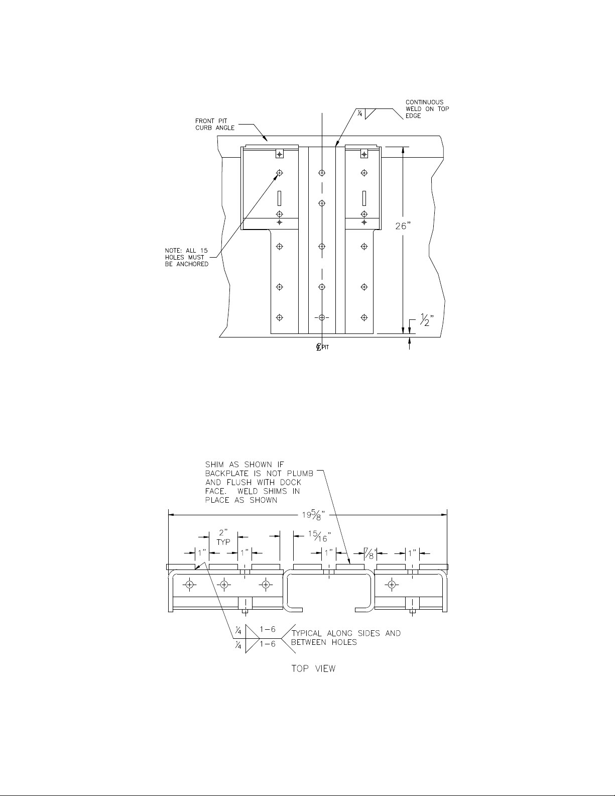
3. Place the bottom edge of the backplate ½” above the driveway and centre with
the pit. If the driveway is susceptible to frost heaving, remove material from the
driveway under the restraint to provide additional clearance.
4. Drill Ø5/8” dia. holes into the pit wall (minimum 4-5/8” deep) using the backplate
as a template.
5. Check to make sure that the backplate is plumb and flush with the dock wall. If it
is not, then use (7) shims 2” wide x 25-5/8” long. (refer to diagram below for
placement) If shims need to be more than ½” thick, longer anchors will be
required.
If the backplate needs to be shimmed out more than 1”, a buildout bracket will be
required (Contact Nordock In

Improper installation that allows the pendant dock leveler lip to support the weight of
the dock leveler could result in serious injury or death. It is sometimes necessary to
install lip deflector plates to prevent the possibility of the pendant lip storing on top of
or behind the restraint backplate. Refer to diagram below. Materials to be supplied
by installer.
The anchors should be installed as the holes are drilled to prevent the
restraint from shifting.
The anchor bolt heads MUST be tight against the backplate to prevent
interference with the carriage assembly
6. Anchor the restraint backplate to the dock face using the (15) 5/8” dia. x 4” long
anchors provided. The anchor bolts must be torqued to 100 ft-lbs. to achieve
their maximum holding strength.
If the top portion of the roller track plate is in contact with the front pit curb angle
(ie. 24” deep pit) weld across the top of the backplate to the curb angle.
CAUTION
!
WARNING

NEVER weld on the restraint after it has been wired to the control box and the
power is on. Damage to the controls or wiring may result.
7. Reinstall the carriage assembly into the backplate weldment. (reference diagram
below)
a. Attach the four springs to the spring bar and the top of the backplate
b. Slide the carriage assembly into the track
c. Bolt the spring bar to the bottom of the carriage assembly
d. Install the spring and motor covers
When lifting the carriage during service or assembly, use a lifting device. Lifting by
hand may result in back injury.
!
WARN
ING
CAUTION

Before doing any electrical work, the power must be disconnected and properly
locked/tagged off. Failure to do so could result in death or serious injury. All
electrical work must meet all applicable codes and be carried out by a qualified
technician.
The control voltage for this restraint is 24 VDC. All motor power wires or other high
voltage wires should be run in a separate conduit.
8. Mount the control box inside the building, to the left of the doorway, 4 ft. above
the floor. Refer to diagram below
~
!
WARNING
NOTE
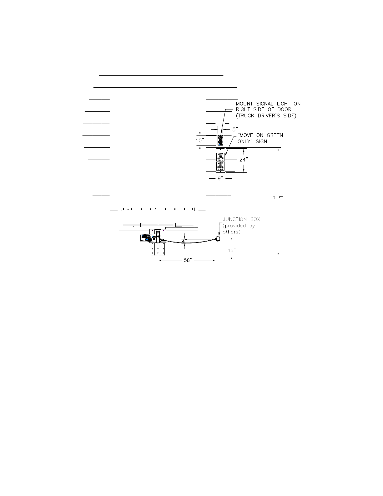
9. The outside signal light is to be placed approximately 9 ft above the driveway on
the driver’s side of the door opening as shown in the diagram below. Drill a hole
through the wall at the centre of the signal light mounting position.
10.Run a length of 18/3 (18 ga. min.) electrical cable (not supplied) from the control
box location through the wall. Make connections in panel and signal light
assembly as indicated in the wiring diagram located at the back of this manual.
11.Fasten the signal light housing to the wall.
12.Mount the “Move On Green Only” sign provided to the exterior wall under the
signal light as shown in the diagram above.
13.
The restraint includes a length of 18/5 cable for connecting to an exterior
mounted junction box (to be provided by others) Mount the junction box to the
exterior wall adjacent to the restraint in the location shown in the diagram above.
14.
There are 5 electrical connections to be made between the exterior junction box
and the control panel. Run a length of 18/5 (or one 18/3 and one 18/2) electrical
cable (not provided) from the control box to the exterior junction box. Make
connections inside the control box and junction box as indicated on the wiring
diagram located at the back of this manual.
15. Bring 110/1/60 power to panel and wire according to the diagram located at the
back of this manual.
CAUTIO
Capacit
Mode

16. Apply power to the control box and verify correct operation as follows:
a. One light must be on, both interior and exterior at all times.
b. With the hook in the released position, the exterior light will be solid
GREEN and the inside light will be solid RED.
17. If the lights do not operate as described above, there is a field wiring problem.
Turn off the power and check the wiring per the Wiring Diagram at the back of
this manual. Rewire as required.
Once the previous electrical and mechanical installs are complete, the hook
STORED POSITION LEARNING PROCEDURE must be carried out.
This procedure needs to be carried out prior to hooking up the battery
backup system.
Stored Position Learning Procedure
•Hook must be in the stored position
•Wires to battery must be disconnected
•Remove fuse on right hand side of circuit board (picture above)
•Press and hold in the yellow “RESTRAINT BYPASS” button on the front of
the panel (if panel has keyswitch instead of button – turn and hold the
keyswitch in the bypass position)
•With the button held in, re-install the fuse. There will be a series of short
beeps followed by a long beep
•Release the yellow button once the long beep starts
When the sequence is complete, the light on the front of the panel should be solid
red and the outside traffic light should be green.
VERY IMPORTANT NOTE !!!
Remove fuse
to shut power
off to the
control board

NOTE:
If you have any other combination of inside/outside lights, shut the power off to the panel
for approximately 10 seconds and then turn it back on. Press the “RELEASE” button and
wait for 10 seconds. If the lights do not indicate as specified above, contact the factory at
(866) 885-4276 and ask for technical support.
NOTE: RETURN TRIPS TO CARRY OUT THE “STORED POSITION LEARNING”
PROCEDURE WILL NOT BE COVERED UNDER WARRANTY
The battery may now be connected using the procedure detailed on page 16.
Dock Leveler Interconnect
There is one set of “dry” contacts provided in the AR-10K control panel for the purpose
of interconnecting a powered dock leveler, air seal or other piece of dock equipment.
These contacts close when the inside light is either solid green (TRUCK HITCHED) or
alternately flashing red/green (RESTRAINT BYPASS).
The contacts are rated at 8A@250VAC (PF=1) or 5A@24VDC.
These contacts are NOT “motor rated” and are ONLY to be used for control voltage and
current levels.
If the rated coil voltage for the dock leveller motor starter exceeds 250VAC, a
separate stepdown transformer or external relay (with 600V rated contacts) will be
required. (TO BE SUPPLIED AND INSTALLED BY OTHERS)
Refer to the wiring diagram at the end of this manual for the terminal numbering for this
interconnect function.
attery ack-up System
The AR-10K restraint is equipped with a 12VDC battery backup system. In the event of
a power outage, the battery will maintain the hook in the restraining position and the
red/green signal lights (interior and exterior) will remain on.
A fully charged battery will maintain the hook in the raised position and the signal lights
functioning for a period of approximately 24 hours.
The LCD screen on the circuit board inside the panel indicates the approximate charge
still left in the battery.
NOTE
Once the AC power is restored, the battery will begin charging automatically. It takes
approximately 72 hours to fully recharge the battery once it has been exhausted.
NOTE: To extend battery life, the inside and outside lights will flash when the
panel is operating on battery power.
Installing and Connecting the attery
It is strongly recommended not to connect the battery until the control panel has been
mechanically and electrically installed and the power has been turned on. If the battery
is connected prior to the power being hooked up to the panel, it will exhaust itself in
approximately a 24hr period.
NOTE: IF THE BUILDING POWER IS TO BE SHUT OFF FOR MORE THAN A 24HR
PERIOD, IT IS STRONGLY RECOMMENDED THAT THE BATTERY BE
DISCONNECTED UNTIL THE POWER IS RESTORED.
ALLOWING THE BATTERY TO BECOME SEVERELY DISCHARGED MAY CREATE
RESTRAINT OPERATIONAL PROBLEMS ONCE THE POWER IS RESTORED. IF
THIS OCCURS, DISCONNECTING THE BATTERY SHOULD RESTORE NORMAL
OPERATION TO THE RESTRAINT. IF THIS OCCURS, THE BATTERY WILL NEED
TO BE RE-CHARGED OUTSIDE OF THE CONTROL PANEL USING AN EXTERNAL
CHARGER (SUPPLIED BY OTHERS)
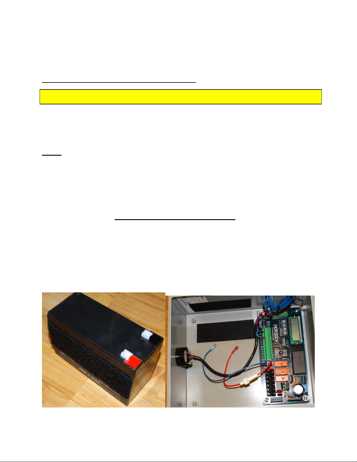
If the battery has been packaged separately (to avoid possible interior panel damage
during shipping), follow the procedure below..
The battery (pictured below - left) is fitted with Velcro on two sides to secure it inside the
control panel (pictured below – right)
IMPORTANT NOTE !!!
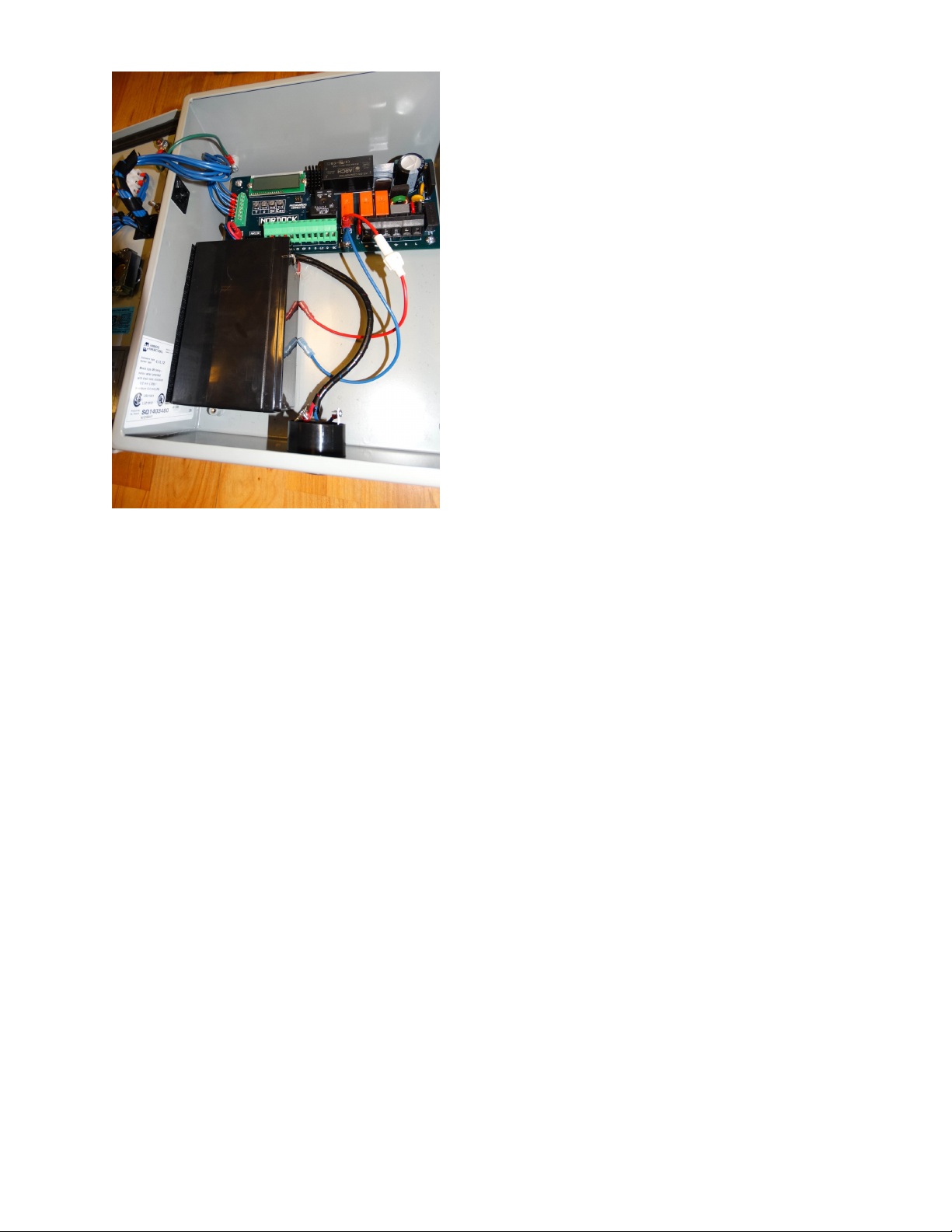
Install the battery in the panel as shown in the
adjacent picture.
It is positioned top of the metal stand-off post
on the bottom left of the panel and the
terminals are oriented to the upper right.
It is attached to the back and left side of the
enclosure with the pre-attached hook and loop
fastener strips.
The battery is then connected by attaching the
red fused wire to the red (+) battery terminal
and the blue wire to the black (-) terminal
This completes the electrical portion of the
restraint install.
18. Instruct the dock workers how to correctly use this truck restraint. The Operating
Procedure can be found in the next section.
Operation
Before operating or maintaining this truck restraint, read and follow the safety
practices contained in this manual. Failure to follow the guidelines in this manual
and those in effect in the workplace can result in serious bodily harm and
equipment damage.
Do not load or unload any truck unless you make certain the AR-10K Rotating
Hook restraint has securely engaged the truck’s ICC bar and that the truck brakes
are set. If the AR-10K Truck Restraint does not engage the truck’s ICC bar for
whatever reason, THE TRUCK’S WHEELS MUST BE CHOCKED BEFORE
LOADING OR UNLOADING CAN BEGIN.
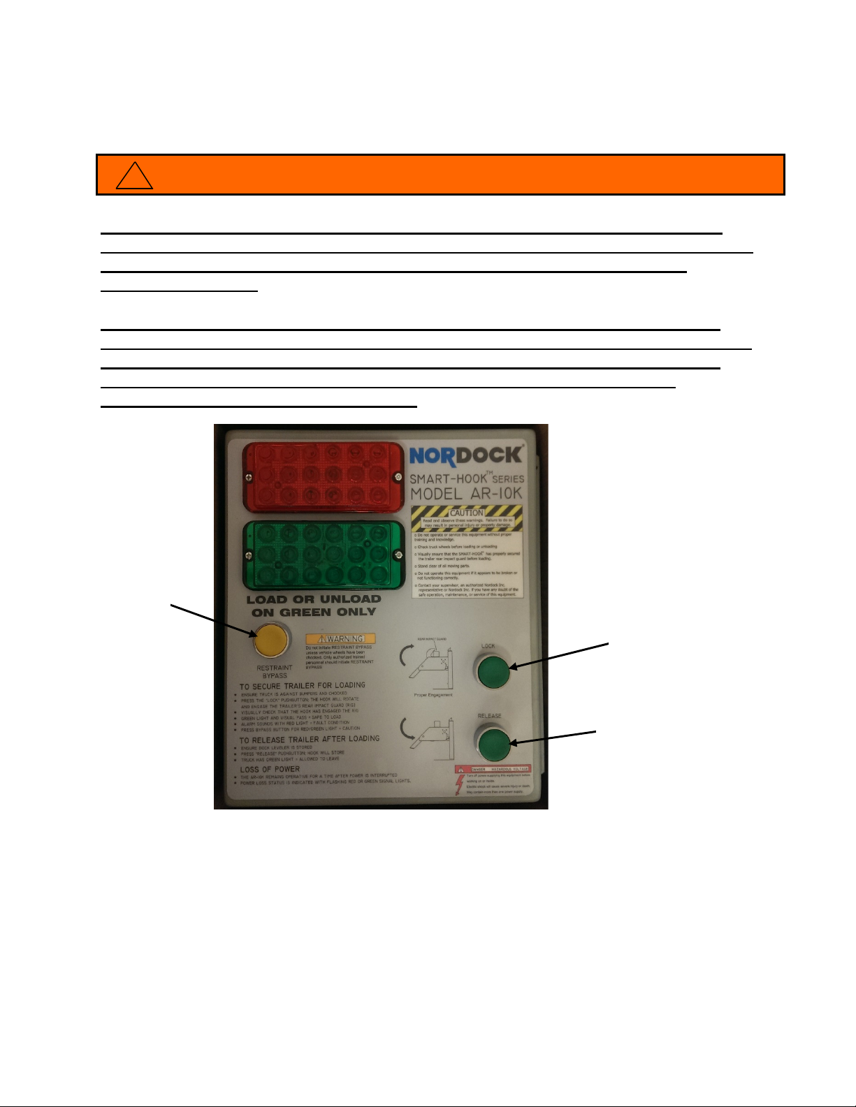
This section covers correct trailer restraint operation using the standard AR-10K control
panel (pictured above)
If the control panel provided differs from what is shown above, the operating instructions
will be given on the panel cover.
STANDARD CONTROL PANEL
LOCK
RELEASE
RESTRAINT
BYPASS
!
WARNING
Other NORDOCK Industrial Equipment manuals


Popular Industrial Equipment manuals by other brands


Haas Automation
Haas Automation UMC-1000 Operator's manual supplement

FTI
FTI LBRA-7 Operation, maintenance, and repair manual

Vestil
Vestil WTJ-4 Series instruction manual

Eaton
Eaton Power Defense Instruction leaflet

ESCO Technologies
ESCO Technologies ETS-Lindgren 5247 quick start guide

IBC
IBC SL 26-260 G3 quick start guide