NOREMAT Optima 51 User manual
Optima
ARTICULATED SIDE-ARM
Operator’s MANUAL
Eco-friendly printing on 100% recycled paper.
This book contains pictures that are not contractual.
Translation of the operator’s manual original version
Book ref : 120076 Index : B

Operator’s manual
Optima 51 / M51 / M56 / M57T / 60T 2
Dynapôle Ludres/Fléville, 166 rue Ampère/BP 60093 - 54714 LUDRES - FRANCE - Tél.+33 (0)3 83 25 69 60 - Fax. +33 (0)3 83 26 12 85
Index
INTRODUCTION 4
RECOMMENDATIONS 5
RESPONSIBILITIES OF THE USER 6
GENERAL SAFETY RULES 7
1. Contact with oil 7
2. Noise/dust 7
3. Vibrations 8
4. Heat 8
5. Delivery 8
6. Before tting to the tractor/cv 9
7. Before starting the rotor
9
8. Before leaving the tractor/cv 9
9. Transport of the machine by lorry 10
9 1Unloading 12
9 2Externaldimensionsofthemachines 13
CHAPTER 1 : TECHNICAL CHARACTERISTICS 15
1. Description of the machine 15
2. Technical specications
16
2 1Performance 16
2 2Weights 17
2 3Rotorhydrauliccircuit 18
2 4Movementhydrauliccircuit 18
2 5FIltrationandcooling 18
2 6Hydrauliccylinderpressures 19
2 7Dual-Pressure‘breakback’systempressures 20
2 8Hydraulicpumppressures 21
3. Types of mounting frame 22
3 1Quickmountingframe 22
3 2‘C’mountinginterfaceformultipurposeframealreadyinplace 22
3 3Automaticchassisattachment 23
3 4Adjustmentofpalonnier/toplinkassembly 24
4. Transport position between worksites
25

Operator’s manual
Optima 51 / M51 / M56 / M57T / 60T 3
Dynapôle Ludres/Fléville, 166 rue Ampère/BP 60093 - 54714 LUDRES - FRANCE - Tél.+33 (0)3 83 25 69 60 - Fax. +33 (0)3 83 26 12 85
CHAPTER 2 : OPERATION AND MAINTENANCE 27
1. Safe use of the machine 27
2. Identication of movements 29
3. Identication of controls 30
4. Preperation and attachment 31
4 1Recommendationsbeforeattaching 31
4 2Attachmentofthemachinetothetractor/cv 32
4 3Counterbalancingthetractor/cv 35
5. First-time operation 36
5 1Beforestartingwork 36
5 2Startingtherotor 36
5 3Stoppingtherotor 37
6. Working position 38
7. Removal 39
8. Storage 39
9. Maintenance 40
9 1Bolttoghteningtorques 40
9 2Dailymaintenance 40
9 3Replacementoftherotor 41
9 4Maintenanceofthecuttingtool 41
9 5Maintenanceoftheaccumulator 41
9 6Maintenanceoftheradiator 41
9 7Armshock-absorberandit’sreplacement 42
10. Greasing 43
10 1Recommendationsaboutgreasing 43
10 2Greasingplanandintervals 43
10 3PTOdriveshaftgreasing 44
11. Oil changes 45
11 1Recommendationsaboutoilchanges 45
11 2Rotorandmovementhydrauliccircuitoilchanges 46
11 3Oilltercartridgereplacement 46
11 4Gearboxoilchange 46
12. Warranty 47
12 1Warrantyapplication 47
12 2Importantnumbers 48
Notes 49
Operator’s manual
Optima 51 / M51 / M56 / M57T / 60T 4
Dynapôle Ludres/Fléville, 166 rue Ampère/BP 60093 - 54714 LUDRES - FRANCE - Tél.+33 (0)3 83 25 69 60 - Fax. +33 (0)3 83 26 12 85
INTRODUCTION
Congratulations on acquiring your new side-arm mower/ail-cutter*
Model
OPTIMA 51
OPTIMA M51
OPTIMA M56
OPTIMA Visiobra M57T - OPTIMA 60T
From it’s introduction, OPTIMA has given the user, greater benets of ease of operation and operating
comfort not found in a rear mounted arm machine.
We hope that it will give you the satisfaction that you justiably expect and that motivated your choice.
SAFETY ALERT SYMBOL
This symbol identies the important safety messages in the manual. When you
see it, take note about the risks, read the accompanying message carefully and
inform other users.
This specication and operation manual contains the information that will enable you to:
1.Familiarise yourself with your machine and take full advantage of it’s technical renements
in the best usage conditions.
2.Obtain optimum performance by simple, but strict observance of
the maintenance recommendations.
3.Deal with incidents that do not require the help of a specialist, without wasting time.
For the safety of any persons nearby, it is very important to follow
the advice given in this manual.
ATTENTION
Your side arm mower must NEVER be used as a lifting device.
*To help with the reading of this manual, the terms, ail mower and articulated side-arm mower are
covered by the word ‘machine’. Terms for ‘cutting head’, reciprocating knife etc will be referred to as
the ‘tool’. Carrying vehicles other than conventional agricultural tractors eg Fastrac, Unimog etc will be
referred to as cv’s.

Operator’s manual
Optima 51 / M51 / M56 / M57T / 60T 5
Dynapôle Ludres/Fléville, 166 rue Ampère/BP 60093 - 54714 LUDRES - FRANCE - Tél.+33 (0)3 83 25 69 60 - Fax. +33 (0)3 83 26 12 85
RECOMMENDATIONS
Your machine is likely to be tted to an agricultural tractor.
NOREMAT would like to draw your attention to the following points :
- Please refer to the relevant authority in your country or state for;
-required certicates of competence to drive and use a tractor/mower combination on
the public highway or other;
-related Health and Safety regulations and requirements.
The job in hand and the use of your machine, just like the whole tractor will necessitate a period of
acclimatization.
NOREMAT will assist you with information and advice.
It is recommended that you make contact with a NOREMAT technician to establish your informational
and instructional needs in relation to the machine and it’s use.
Furthermore, it is desirable that each user can benet from the experience and expertise of NOREMAT,
your Direct-Constructor.
Operator’s manual
Optima 51 / M51 / M56 / M57T / 60T 6
Dynapôle Ludres/Fléville, 166 rue Ampère/BP 60093 - 54714 LUDRES - FRANCE - Tél.+33 (0)3 83 25 69 60 - Fax. +33 (0)3 83 26 12 85
RESPONSIBILITIES OF THE USER
The user is responsible to adhere strictly to the safe-use regulations
and safety points which are dened in this manual.
As with the driving of all machines, the user must match his speed
of travel in the transport position or during work, to the condition of
the roadway or terrain.
Before carrying out any operation with your machine, you are advised to read this section carefully.
All modications carried out on the machine are the sole responsibility of the person instigating them.
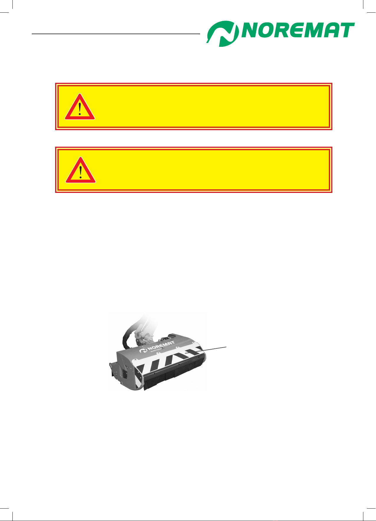
To use the machine for mowing (rotor turning in the opposite direction to the tractor wheels), it is
imperative that the front hood and aps are tted to avoid the risk of debris being thrown from the rotor.
gure 1.01
example of
hood and aps
If these regulations are not respected, responsibility lies with the user alone.
Operator’s manual
Optima 51 / M51 / M56 / M57T / 60T 7
Dynapôle Ludres/Fléville, 166 rue Ampère/BP 60093 - 54714 LUDRES - FRANCE - Tél.+33 (0)3 83 25 69 60 - Fax. +33 (0)3 83 26 12 85
GENERAL SAFETY RULES
It is essential to follow the instructions in this manual to ensure the
safety of persons operating or in the vicinity of the machine.
1. Contact with oil
At the time of oil changes or when working on any components which
may retain hydraulic pressure, ALWAYS wear adequate safety equipment
Body
Protection
Gloves Face
Visor
-In the event of contact with the skin:
If a high pressure jet of oil is applied to the skin there is a danger of the oil penetrating
the surface. The injured person should be taken to hospital even if no wound is apparent.
Remove all contaminated clothing. Wash the suspected area immediately with plenty of soap
and water.
-In the event of contact with the eyes:
Wash immediately with plenty of water. Hold the eyelids apart for at least 15 minutes.
-Ingestion:
Risk of vomiting and diarrhoea. Do not make the person drink to avoid the risk of inhalation by
the respiratory tracts. Do not drink water.
-Aspiration:
If there is a suspicion that the person may have inhaled oil into the lungs (when vomiting for
instance), take them to hospital immediately.
In all cases seek immediate medical attention
2. Noise / dust
Take necessary precautions against the risk
of exposure to noise and dust during working
and travelling periods.
Wear Ear
Defenders
Operator’s manual
Optima 51 / M51 / M56 / M57T / 60T 8
Dynapôle Ludres/Fléville, 166 rue Ampère/BP 60093 - 54714 LUDRES - FRANCE - Tél.+33 (0)3 83 25 69 60 - Fax. +33 (0)3 83 26 12 85
3. Vibrations
To improve safety and health conditions of workers, the decree 2005-746 from July 4th, 2005 forces
the employer to evaluate the levels of exposure of its employees to the vibrations transmitted to the
whole body, and to start protection of the driver beyond exposure limit values.
These daily exposure limit values are precised in the article R 231-119 of the Labour regulation.
Noremat carried out trial runs to evaluate the level of vibrations emitted by a tractor /machine unit and
transmitted to the operator’s seat. As an indication, the median value recorded is 0.45m/s2 per eight
hours base period in normal work conditions as recommended by the manufacturer.
4. Heat
Take necessary precautions against the risks
due to the heat released by the hydraulic
components (hoses, pump, motor, gearbox,
valve block, rotor shaft).
Wear heat
protection
5. Delivery
Observe safety and handling rules, in particular:
-only use designated slinging points for all slings.
-never lift the machine with slings that are in poor condition or are too weak in lifting capacity.
-check that the means of lifting is satisfactory and suitable to lift the load.
-never stand or walk under the load.
-never attempt to remove the delivery supports (blue pieces) before tting
of the machine has been completed.

Operator’s manual
Optima 51 / M51 / M56 / M57T / 60T 9
Dynapôle Ludres/Fléville, 166 rue Ampère/BP 60093 - 54714 LUDRES - FRANCE - Tél.+33 (0)3 83 25 69 60 - Fax. +33 (0)3 83 26 12 85
6. Before tting to the tractor/cv
-It is necessary that the tractor is equipped with a cab or means of protecting the driver from possible
debris thrown from the tool.
-Check the condition of the PTO shaft guard on the tractor.
-Carefully read the tting instructions supplied with the drive shaft.
-Check all tyre pressures.
7. Before starting the rotor
-Read chapter 2, section 3, ‘Identication of controls’.
-Read the operator’s manual for the tool to be used.
-Do not start the machine in an explosive atmosphere or near inammable items.
-It is recommended that the rst trial be carried out on ground which is rm, at and without obstacles.
-Ensure that the operator is familiar with the tractor/machine combination.
-Check that the control unit is mounted securely in the cab/on the tractor.
-Never start the rotor if anyone is standing within the trajectory of possible debris thrown from the rotor.
-Ensure that all persons remain outside of the working area of the tractor and machine.
-Never remove the front hood of the cutting tool during work when mowing (direction of rotor opposite
to the forward motion of the carrying vehicle, see chapter ‘User responsibilities’).
8. Before leaving the tractor/cv
Before leaving that tractor/cv or allowing anyone to approach, it is imperative to:
- lower the tool to the ground.
- stop the rotor.
- stop the PTO.
- switch the machine off.
- apply the parking brake.
- stop the tractor engine.
General Safety Rules
Operator’s manual
Optima 51 / M51 / M56 / M57T / 60T 10
Dynapôle Ludres/Fléville, 166 rue Ampère/BP 60093 - 54714 LUDRES - FRANCE - Tél.+33 (0)3 83 25 69 60 - Fax. +33 (0)3 83 26 12 85
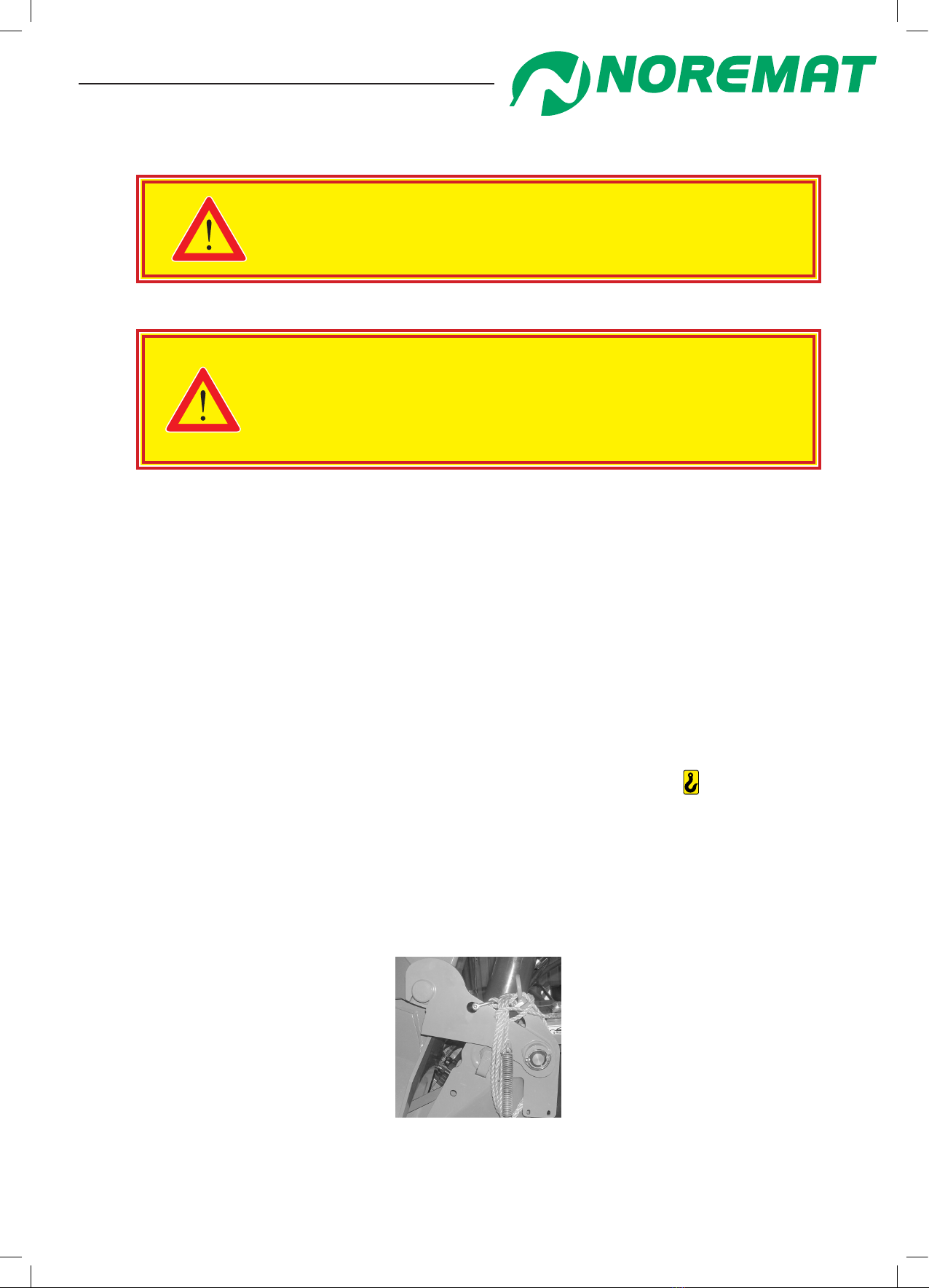
9. Transport of the machine by lorry
The machine should be secured to the lorry in such a way as to
guarantee absolute safety for nearby persons and equipment.
See Safety Rules on Page 7.
Precautions for carriage when not tted to a tractor or carrying vehicle:
It is essential to lock the arm with the locking kit (blue supports)
supplied with the machine (Figures 1.02, 1.03, 1.04, 1.05, 1.06).
Contact NOREMAT who can supply you with the correct locking kit.
For safety reasons, the equipment is delivered in the ‘delivery’ position. In this position, machine
movements are locked by supports that serve both for lifting the machine and for anchoring it
to the lorry.
These supports are identied by their unusual blue colour.
When it is delivered, the machine is unloaded and placed on the ground on it’s stands at the correct
height to be tted to a standard tractor.
The supports should not be moved until the machine is tted to the tractor and started.
Observe lifting safety rules. In particular:
-use only designated points to attach slings and lift only at these points shown
in the following diagrams.
-never lift the machine with slings that are in poor condition or incapable of lifting
the required weight.
-never walk or stand under the machine.
gure 1.02
General Safety Rules
Operator’s manual
Optima 51 / M51 / M56 / M57T / 60T 11
Dynapôle Ludres/Fléville, 166 rue Ampère/BP 60093 - 54714 LUDRES - FRANCE - Tél.+33 (0)3 83 25 69 60 - Fax. +33 (0)3 83 26 12 85
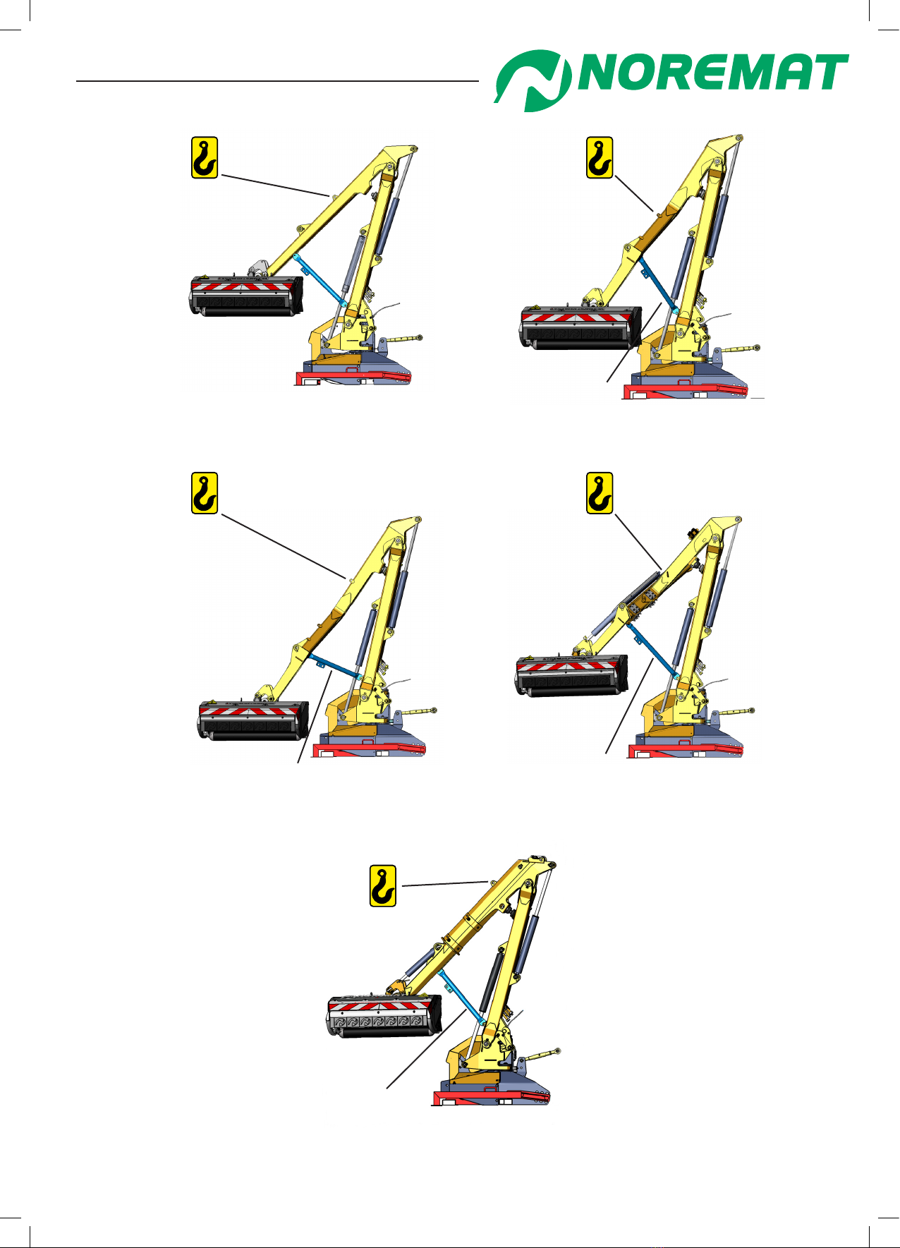
General Safety Rules
Locking kit
119324
gure 1.03 :Optima51
Locking kit
118875
gure 1.04 :Optima:M51
Locking kit
118877
gure 1.05 :Optima:M56
Locking kit
118867
gure 1.06 :Optima:M57T
Locking kit
123969
gure :Optima:60T
Operator’s manual
Optima 51 / M51 / M56 / M57T / 60T 12
Dynapôle Ludres/Fléville, 166 rue Ampère/BP 60093 - 54714 LUDRES - FRANCE - Tél.+33 (0)3 83 25 69 60 - Fax. +33 (0)3 83 26 12 85
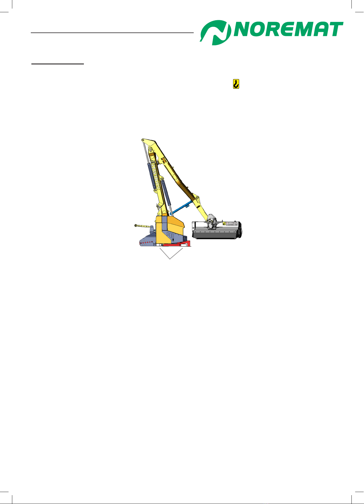
9 1Unloading
- Lift the machine with the help of a suitable gantry crane :
- travelling crane : use the lifting point shown by the symbol in the diagrams
on the previous pages.
- fork truck : use only if the necessary kit (red pieces) is tted to the machine ( gure 1.07)
Kit for fork truck lift:
(red pieces) tted
for the entry of the forks.
gure 1.07
Move clear of the lorry and t the adjustable stands to the machine
- Lower the machine slowly. Before it touches the ground, adjust the stands so that
it will remain level.
- Place the machine on the ground.
- Remove the parts tted for adapting it to the fork truck lifting means.
You now only need to hitch the machine to the tractor/carrying vehicle. See paragraph ‘Fittings and
mountings’.
General Safety Rules
Operator’s manual
Optima 51 / M51 / M56 / M57T / 60T 13
Dynapôle Ludres/Fléville, 166 rue Ampère/BP 60093 - 54714 LUDRES - FRANCE - Tél.+33 (0)3 83 25 69 60 - Fax. +33 (0)3 83 26 12 85
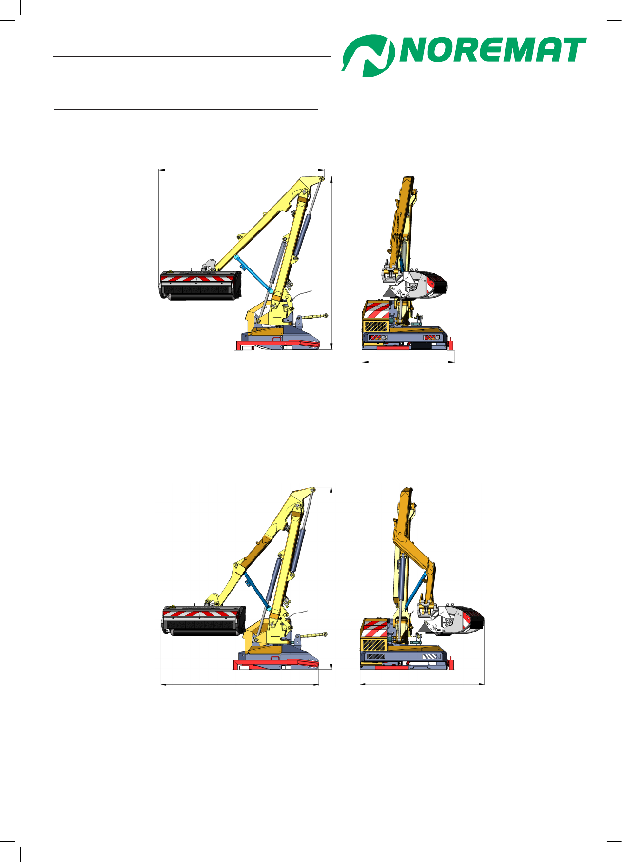
9 2Externaldimensionsofthemachines
2948 mm
3393 mm
2320 mm
gure 1.09 :
Optima M51
gure 1.08 :
Optima 51
3170 mm
3314 mm
1777 mm
General Safety Rules

Operator’s manual
Optima 51 / M51 / M56 / M57T / 60T 14
Dynapôle Ludres/Fléville, 166 rue Ampère/BP 60093 - 54714 LUDRES - FRANCE - Tél.+33 (0)3 83 25 69 60 - Fax. +33 (0)3 83 26 12 85
General Safety Rules
gure 1.10 :
Optima M56
gure 1.11 :
Optima Visiobra M57T
gure :
Optima 60T
3238 mm 2269 mm
3391 mm
3188 mm 2273 mm
3353 mm
3064 mm 1775 mm
3490 mm
3400 mm
90 mm
Operator’s manual
Optima 51 / M51 / M56 / M57T / 60T 15
Dynapôle Ludres/Fléville, 166 rue Ampère/BP 60093 - 54714 LUDRES - FRANCE - Tél.+33 (0)3 83 25 69 60 - Fax. +33 (0)3 83 26 12 85
CHAPTER 1 : TECHNICAL CHARACTERISTICS
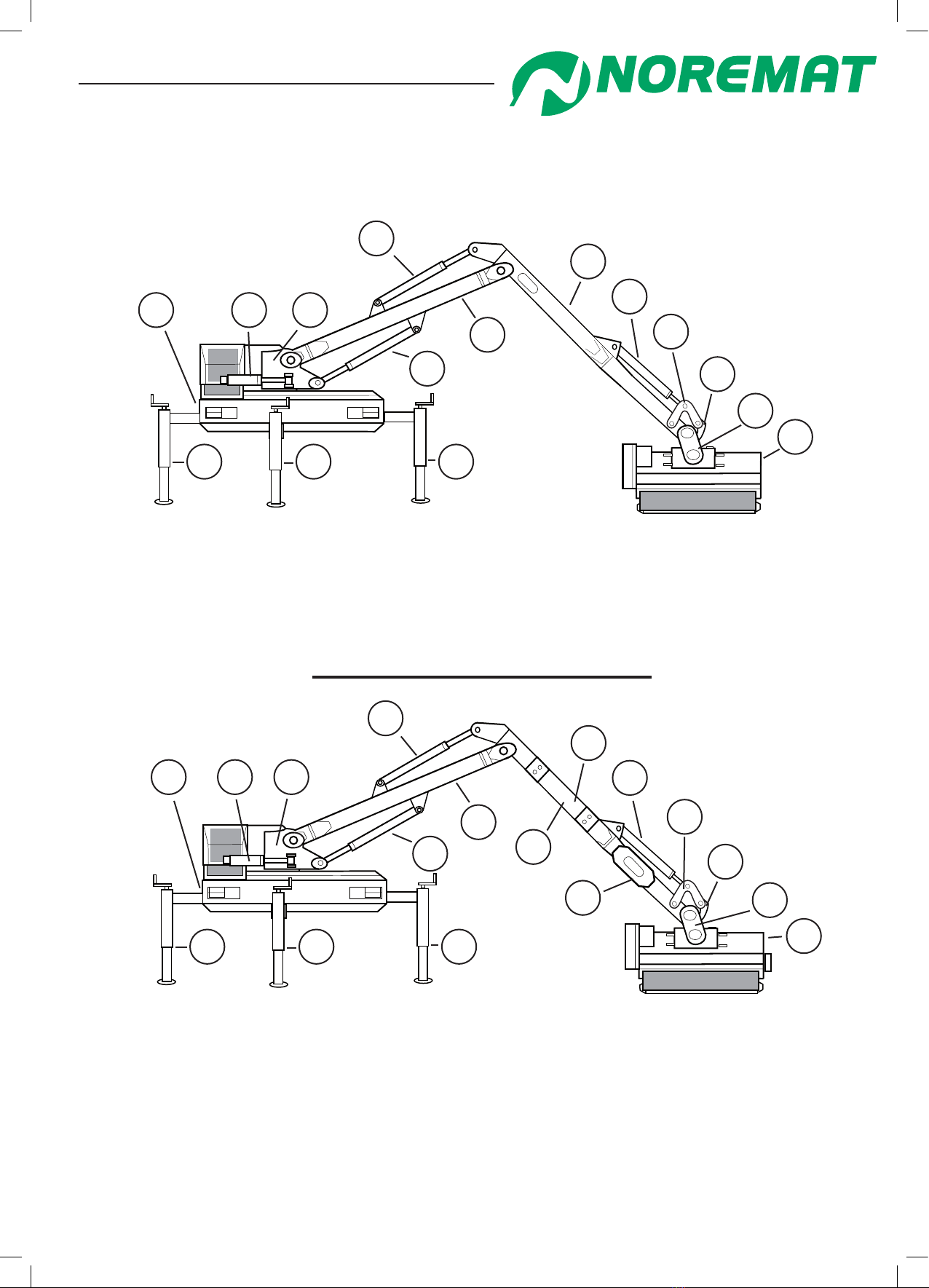
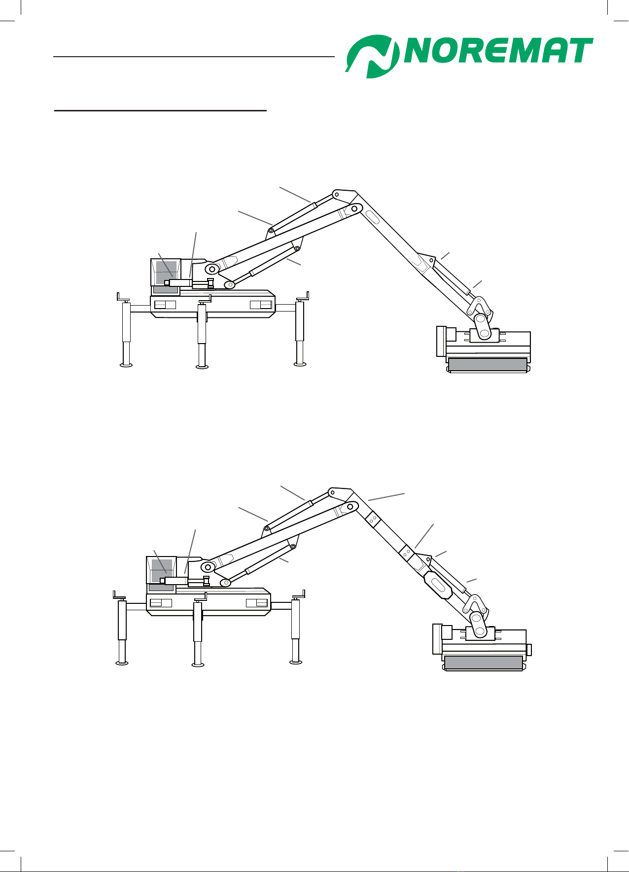
1. Description of the machine
1 - Frame
2 - Machine orientation cylinder
3 - Arm pivot assembly
4 - Second-arm cylinder
5 - Second-arm
6 - Tool orientation cylinder
7 - Transfer link bracket
8 - Angle transfer bracket
9 - Tool pivot bracket
10 - Tool
11 - First-arm
12 - First-arm cylinder
13 - Parking stands
51 / M51 / M56
gure 1.12
11
9
8
7
6
2
5
3
12
4
13 13
13
10
1
1 - Frame
2 - Machine orientation cylinder
3 - Arm pivot assembly
4 - Second-arm cylinder
5 - Integral telescopic arm inside
second arm
6 - Tool orientation cylinder
7 - Transfer link bracket
8 - Angle transfer bracket
9 - Tool pivot bracket
10 - Tool
11 - Telescopic arm
12 - Telescopic support arm
13 - First-arm
14 - First-arm cylinder
15 - Parking stands
gure 1.13
1
5
8
2
7
9
13
3
14
4
6
15 15 15
12
11
10
M57T
Operator’s manual
Optima 51 / M51 / M56 / M57T / 60T 16
Dynapôle Ludres/Fléville, 166 rue Ampère/BP 60093 - 54714 LUDRES - FRANCE - Tél.+33 (0)3 83 25 69 60 - Fax. +33 (0)3 83 26 12 85
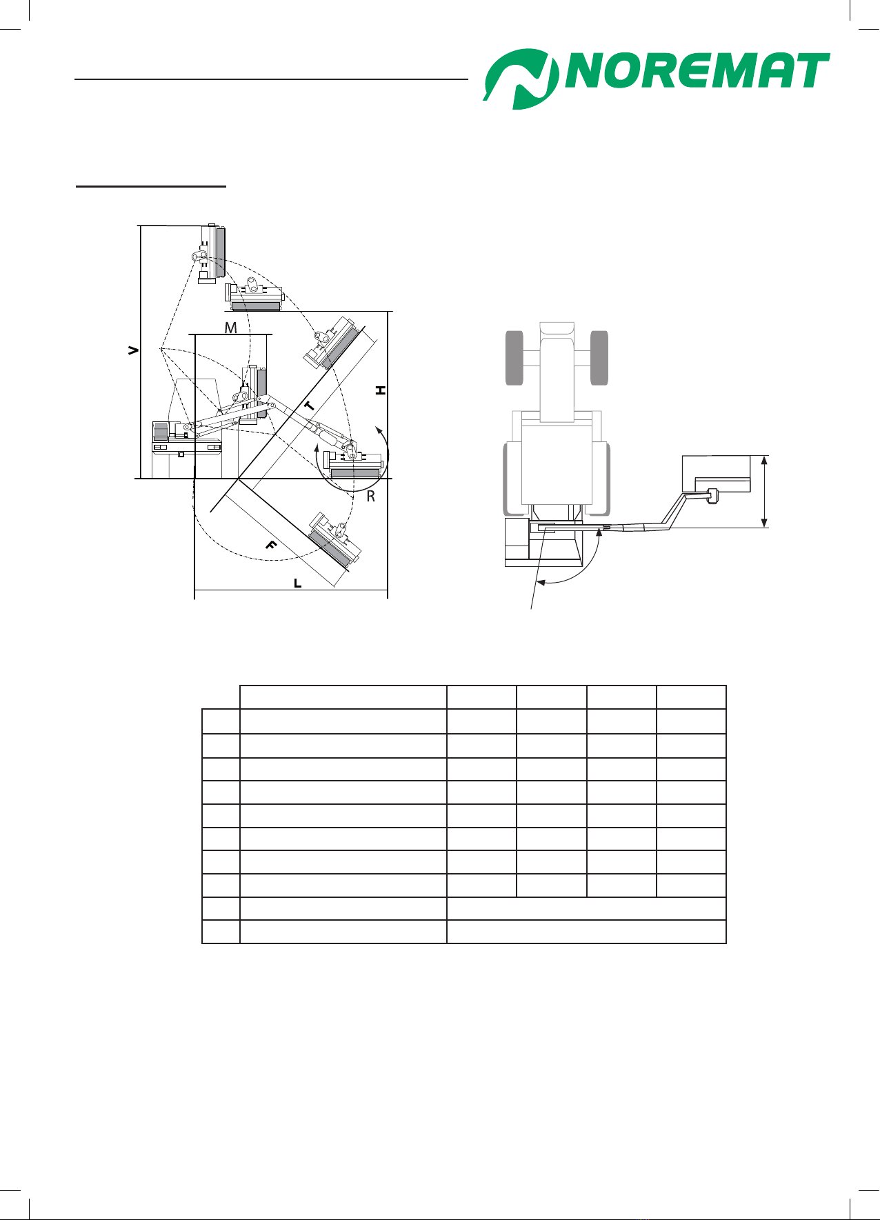
2. Technical specications
2 1Performance
Model 51 M51 M56 M57T
LMaximum lateral reach*5.10 m 5.10 m 5.60 m 5.70 m
V Vertical reach 6.55 m 6.55 m 7.00 m 7.10 m
T Bank reach 5.25 m 5.25 m 5.70 m 5.80 m
H Over-hedge reach 4.40 m 4.40 m 4.65 m 4.70 m
F Ditch reach 3 m 3 m 3.50 m 3.60 m
M Minimum lateral reach 1.75 m 1.75 m 1.85 m 1.75 m
N Forward reach 0.98 m 1.63 m 1.63 m 2.33 m
Telescopic NO NO NO YES
P Orientation angle 100°
R Tool orientation 230°
P
N
gure 1.14
*Measured from the centreline of the tractor.
Average dimensions, variable according to the type of tractor.
Technical characteristics
Operator’s manual
Optima 51 / M51 / M56 / M57T / 60T 17
Dynapôle Ludres/Fléville, 166 rue Ampère/BP 60093 - 54714 LUDRES - FRANCE - Tél.+33 (0)3 83 25 69 60 - Fax. +33 (0)3 83 26 12 85
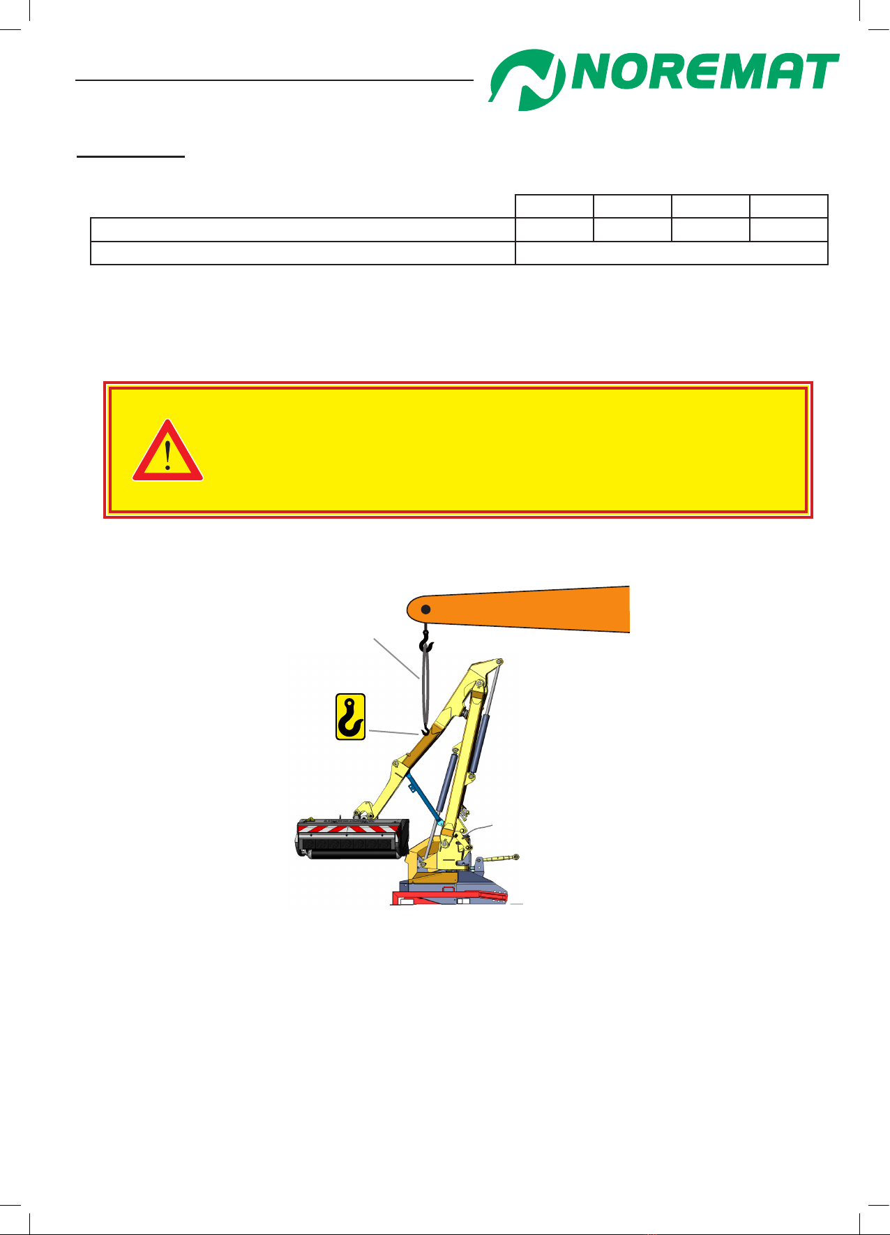
2 2Weights
51 M51 M56 M57T
Weight in working set-up (without fool tted) 1220 kg 1250 kg 1300 kg 1400 kg
Maximum tool weight at end of arm*390 kg
* Except with written permission from NOREMAT
To nd out the weight of the tool, refer to the appropriate User Manual.
A sling may be used to lift the machine.
For safety reasons we recommend using a sling of 2 tonnes minimum
capacity for Optima models.
See the chapter <Transport of the machine by lorry> for advice on safety
and handling
Means of Lifting
sling
gure 1.15 : Lifting of a machine using a sling.
Technical characteristics
Operator’s manual
Optima 51 / M51 / M56 / M57T / 60T 18
Dynapôle Ludres/Fléville, 166 rue Ampère/BP 60093 - 54714 LUDRES - FRANCE - Tél.+33 (0)3 83 25 69 60 - Fax. +33 (0)3 83 26 12 85
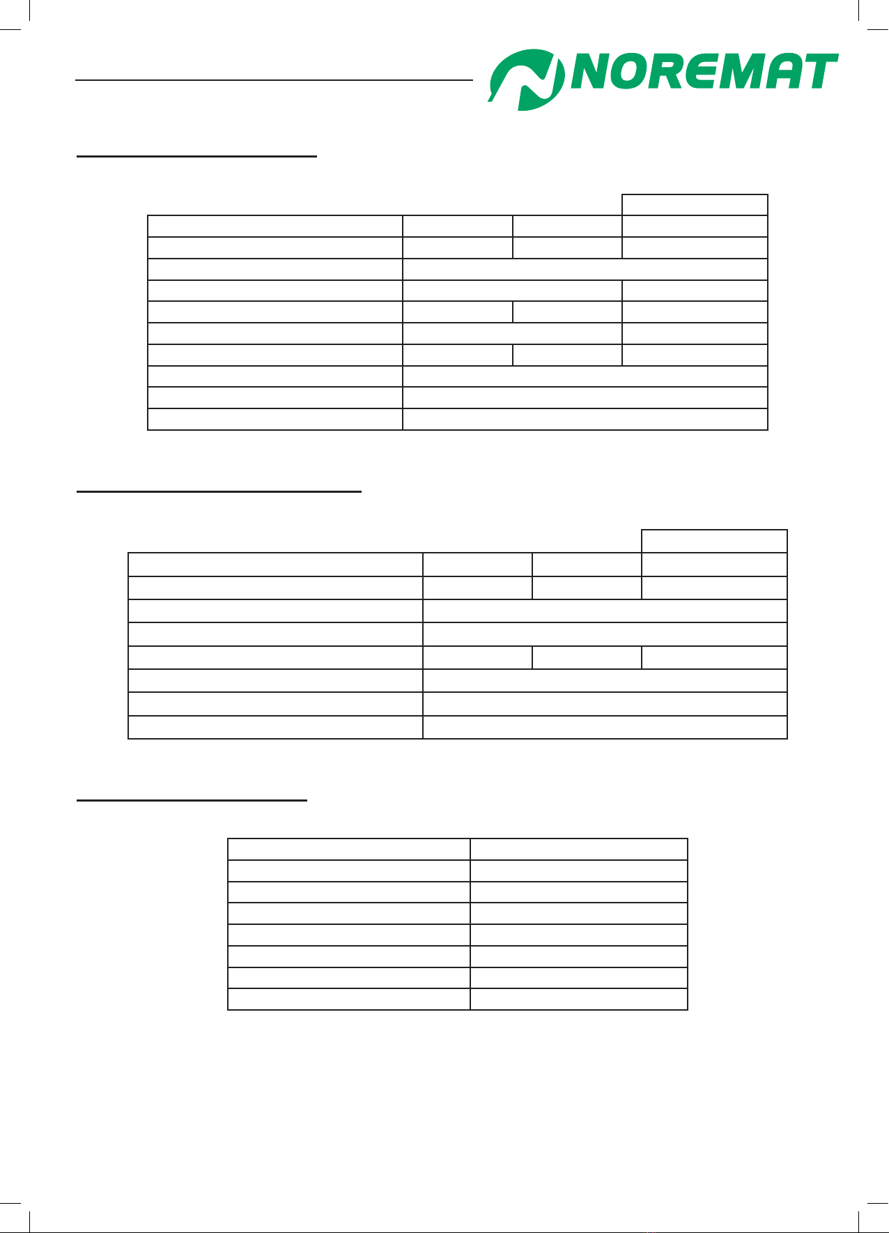
2 3Rotorhydrauliccircuit
Hydroshift
Power Take Off speed 540 rpm 1000 rpm /
Gearbox ratio 1 : 4 1 : 2,5 /
Hydraulic pump piston
Capacity 46 cc 41 cc
Flow 100 lpm 115 lpm 86 lpm
Maximum pressure 300 bar 280 bar
Power 68 CV 78 CV 57 CV
Controls electric
Hydraulic motor piston
Capacity 35 cc
2 4Movementhydrauliccircuit
Hydroshift
Power Take Off speed 540 rpm 1000 rpm /
Gearbox ratio 1 : 4 1 : 2,5 /
Hydraulic pump gear
Capacity 17 cc
Flow 36 lpm 42 lpm 36 lpm
Maximum service pressure at pump outlet 220 bar
Hydraulic cylinder double acting
Electrical equipment parachute valves on 1st and 2nd arms
2 5Filtrationandcooling
Reservoir capacity 70 liters
Reservoir pressurisation not pressurised
Reservoir oil specication HV 46
Filtration type submerged suction return
Filtration 10 microns absolute
Radiator construction aluminium
Cooling fan electric, Ø 305mm
Heat exchange capacity 14.5 kW
Technical characteristics
Operator’s manual
Optima 51 / M51 / M56 / M57T / 60T 19
Dynapôle Ludres/Fléville, 166 rue Ampère/BP 60093 - 54714 LUDRES - FRANCE - Tél.+33 (0)3 83 25 69 60 - Fax. +33 (0)3 83 26 12 85
2 6Hydrauliccylinderpressures
51 / M51 / M56
gure 1.16
125 bar
190 bar
160 bar for 51 and M51
210 bar for M56
210 bar
210 bar
140 bar
160 bar
M57T
gure 1.17
210 bar*
125 bar*
125 bar
190 bar
210 bar
140 bar
160 bar 210 bar
210 bar
*Telescopic cylinder pressure is checked on cylinder inside the second-arm.
Technical characteristics
Operator’s manual
Optima 51 / M51 / M56 / M57T / 60T 20
Dynapôle Ludres/Fléville, 166 rue Ampère/BP 60093 - 54714 LUDRES - FRANCE - Tél.+33 (0)3 83 25 69 60 - Fax. +33 (0)3 83 26 12 85
Technical characteristics
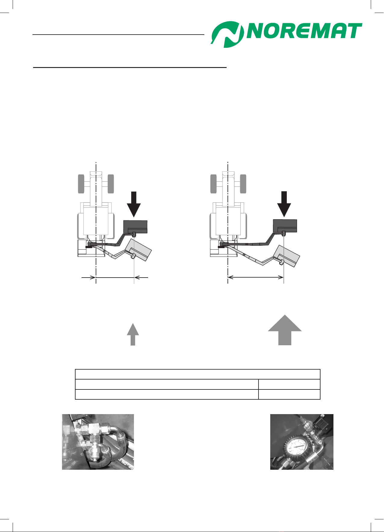
2 7Dual-Pressure‘breakback’systempressures
Your machine is equipped as standard with an arm ‘breakback’ system called Dual-Pressure
(gure 1.18) French patent applied for 15th Sept 2004.
Normally, in the event of meeting an obstacle or when the forward speed is too high for the vegetation
being cut, the pressure rises in the orientation cylinder of the machine. When a designated pressure is
exceeded, a regulating valve opens and allows the arm to ‘breakback’ towards the rear.
In the Dual-Pressure system, the opening pressure of the regulating valve depends on the position of
the arm. If the distance from the centre-line of the tractor to the tool is more than the halfway reach
point, the pressure necessary for ‘breakback’ will be increased, or reduced if nearer.
gure 1.18
breakback pressure
110 bar
distance between centreline of
tractor and tool is less than half of
the maximum arm reach
obstacle
breakback pressure
160 bar
distance between centreline of
tractor and tool is more half of
the maximum arm reach.
obstacle
Dual-Pressure system
Pressure at DP valve test point (g 1.19 & 1.20) 110 bar
Pressure (high setting) at valve block 160 bar
gure 1.20
gure 1.19
This manual suits for next models
4
Table of contents
Popular Farm Equipment manuals by other brands

Horizont
Horizont trapper AB15 instruction manual

Tatu Marchesan
Tatu Marchesan GNFH Operator's manual

Krone
Krone X-Disc 620 Original operating instructions

Spearhead
Spearhead Trident 4000 Handbook

AG SHIELD
AG SHIELD LandRoller OPERATOR’S HANDBOOK AND PARTS MANUAL

Econo-Wrap
Econo-Wrap EW-450A Operator's manual


AgLand
AgLand POWERMERGER6618 Operator's manual

Landoll
Landoll 2512 Series Operator's manual

New Holland
New Holland H9870 Service manual

M K Martin Enterprise
M K Martin Enterprise PULSAR 120 Operator and parts manual

Ovlac
Ovlac MINIVID OPERATING INSTRUCIONS AND SPARE PARTS

Sulky
Sulky Isobus X Series Original instructions