AgLand POWERMERGER6618 User manual

Operator’s Manual &
Parts Catalogue
July 2009
2009
6618

Replacement Parts
To obtain prompt, efcient service, give your dealer the follow-
ing information.
1. Correct stock number.
2. Model number of the machine.
3. Serial number of the Macerator.
The serial number is important in identifying your machine. It
contains information for ordering replacement parts and op-
tions which may vary depending on the serial number identi-
cation.
Measurements are given in U.S. units followed by the equiva-
lent in metric units. Hardware sizes are given in inches for U.S.
hardware and millimeters for metric hardware.
All nuts and bolts are specied in Grade 5 unless otherwise
indicated.

1
Contents
Warranty Registration Form ............................................................................................................................................ 3
Introduction....................................................................................................................................................................... 5
Assembly Instructions ............................................................................................................................................... 6–14
Assembly Procedure .............................................................................................................................................................................. 6
Conveyor Assembly .............................................................................................................................................................................. 10
Hydraulic Motor Assembly ..................................................................................................................................................................11
Hydraulic Fittings and Hoses ..............................................................................................................................................................12
Hydraulic Hose Routing .......................................................................................................................................................................13
Adjustable Arm Stops ..........................................................................................................................................................................14
Maintenance ...................................................................................................................................................................15
Parts Catalogue ........................................................................................................................................................ 17-24
Conveyor...............................................................................................................................................................................................18
Power Merger Kit K108 ......................................................................................................................................................................20
Weight Holder ......................................................................................................................................................................................22
Hydraulics ............................................................................................................................................................................................ 24
Warranty ........................................................................................................................................................... Back Cover


I have instructed the buyer on the above described equipment and included a review of the Operator’s Manual, assembly,
maintenance, safety, and applicable warranty policy.
Dealer’s Signature Date
The above equipment and the Operator’s Manual have been received by me and I have been instructed as to the care, ad-
justments, safe operation, and applicable warranty policy.
Purchaser’s Signature Date
Customer Name:
Address:
City:
Prov/State: Postal/Zip:
Phone No:
Model No:
Serial No:
Dealer:
Address:
City:
Prov/State: Postal/Zip:
Phone No:
Date Purchased:
Check One: Commercial Use Farm Use
AgLand Power Merger 6618™
LIMITED WARRANTY REGISTRATION FORM
The Power Merger 6618 is warranted by AgLand to the original purchaser, to be free of defects in workmanship and material
for a period of one (1) year from date of purchase for farm use (three (3) months from date of purchase for commercial use).
AgLand does not warrant any damage caused by negligence, modications, and/or lack of maintenance (see Maintenance Sec-
tion in Operator’s Manual).
AgLand will not be liable for the cost of shipping or any other cost incurred for replacement or repair of any parts. AgLand is not
liable for any accidents which may occur from or during the operation of the Power Merger 6618, or damage incurred due to
Power Merger failure. The purchaser assumes all responsibility for the operation, care, maintenance and safety.
See back of the Operator’s Manual for complete warranty details.
Failure to return completed registration form to AgLand within thirty (30) days of delivery will VOID the warranty.
This form must be lled out by both the dealer and customer.
Mail to:
AgLand Industries Inc.
Box 479, Arborg, MB
R0C 0A0
DEALER CHECKLIST
Belt tension checked and adjusted
Check conveyor belt runs true and is adjusted to
proper tightness
Hydraulic lines and ttings checked for oil leakage
Hydraulic cylinder cycled several times to delete all air in
cylinder and lines
All reectors in place
All grease ttings greased
All safety procedures have been reviewed with customer
Customer has been instructed to review safety and operat-
ing procedures with all operators annually
I have thoroughly inspected the machine and made adjustments and corrections as needed.
Inspected By Signature Date
White - AgLand Yellow - Customer Pink - Dealer


5
AgLand Industries Inc. is a Canadian owned and oper-
ated company located in central Canada, in the province
of Manitoba. AgLand was founded in 2001 by a group of
innovative entrepreneurs that transformed their ideas
and expertise into a leading manufacturing company of
agricultural crop equipment.
Box 479, Arborg, MB, Canada R0C 0A0
Tel: 204.364.2211
Fax: 204.364.2472
Email: [email protected]
Web: www.aglandindustries.com
Introduction
The Power Merger 6618 is designed to merge a macer-
ated swath to lay beside or on top of an existing swath to
enhance or shorten the length of drying time.
The macerated swath can be merged either to the left or
right side by reversing the conveyors hydraulic motor.
In the operating mode, the conveyor runs at an approxi-
mate 10-12 degree angle when resting on the arm stops.
This angle is to achieve a proper attitude for conveying
and merging crop material.
The reference to left side and right side is determined
when facing the direction of travel during operation of the
Macerator and Power Merger.
NOTE: PAY SPECIAL ATTENTION TO THE SAFETY SECTION
of the Macerator 6610 or 6620 Operator’s Manual in
order to understand the SAFETY CAUTIONS of this attach-
ment.
* This attachment to be installed only on the 2006 and
later 6610 and 6620 Macerator models.
The photographs, illustrations, and data used in this man-
ual were current at the time of printing, but due to pos-
sible in-line production changes, your machine may vary
slightly in detail. The Manufacturer reserves the right to
redesign and change the machine as necessary without
notication.
WARNING
Some pictures in this manual show the machine with
shields removed to allow for a better view of the sub-
ject. The machine must never be operated with any of
the shields removed.
Congratulations, you have just purchased the new Power Merger 6618 attachment for the AgLand Macerator*
6610 and 6620. To get the maximum benet from your Power Merger we suggest that you read this manual
carefully.
6
Assembly Instructions
The Power Merger attachment is shipped partially assembled as follows:
1. Conveyor Assembly - assembled except for Hydraulic Motor Drive.
2. Main Tube and Hook Arm(s) (left and right) - not assembled.
3. Conveyor Lift Arms (4) and Hydraulic Lift Tube – not assembled.
4. Lift Arm Stop Bumper Assemblies – not assembled.
5. Hydraulics - including Hydraulic Lift Cylinder, Drive Motor and Hydraulic Hoses – not assembled.
6. Counter Weight Frame Assembly – not assembled.
7. Windrower attachment, if not equipped with previously – not assembled.
This attachment to be installed only on the 2006 and later 6610 and 6620 Macerator models.
Tractor must be attached to the Macerator during assembly of the Power Merger to prevent the Macerator from becom-
ing unstable.
Assembly Procedure
Assemble parts onto Macerator as follows:
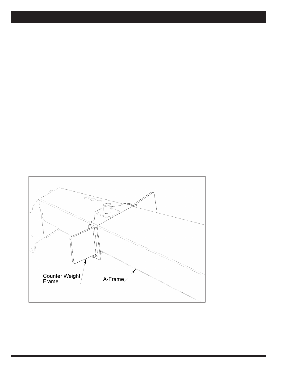
1. Install the counter weight frame on hitch A-frame, see Figure 1.
Add two l00 lb (46 kg) tractor suit-case weights (or equivalent), one on each side to keep the Macerator in
balance BEFORE installing the conveyor assembly.
Figure 1

7
Assembly Instructions
2. Install nylon bushings into left side and right side hook arms, see Figure 2.
Figure 2
3. Assemble and install main frame tube, hook arms and stabilizer braces to hook arms at rear of Macerator.
Leave bolts loose until all frame and arm assemblies are installed, see Figure 3.
Figure 3
8
Assembly Instructions
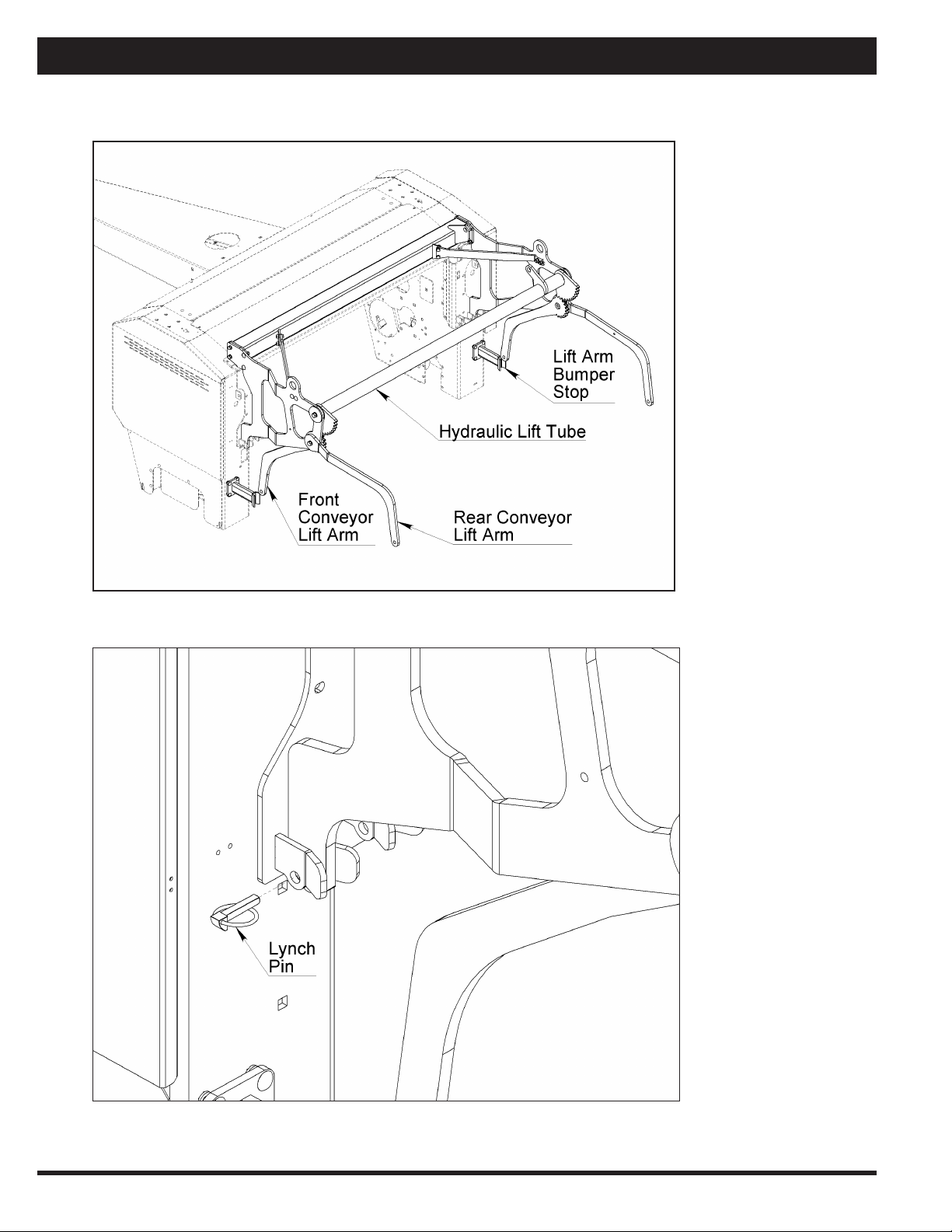
4. Install hydraulic lift tube, front and rear conveyor lift arms and lift arm bumper stops.
Tighten all frame bolts, see Figure 4.
Figure 4
5. Install bottom locking lynch pins, see Figure 5.
Figure 5

9
Assembly Instructions
6. Install hydraulic cylinder and leave in fully retracted (in) position. Ensure index lift arm gear teeth with front
arms are fully down against bumper stops, see Figure 6.
Figure 6
7. Assemble windrower with 10 degree hook mounting plates (supplied with sundry parts).
Install windrower onto Macerator, see Figure 7.
Figure 7
10
Assembly Instructions
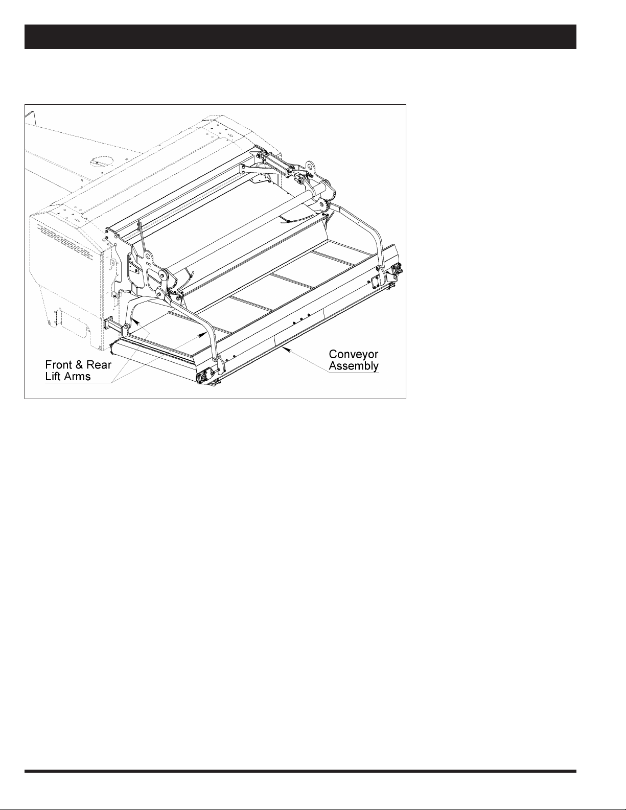
Conveyor Assembly
Assemble conveyor assembly onto front and rear lift arms using ¾” x 2” bolts, nuts and spacers, see Figure 1.
Figure 1
11
Assembly Instructions
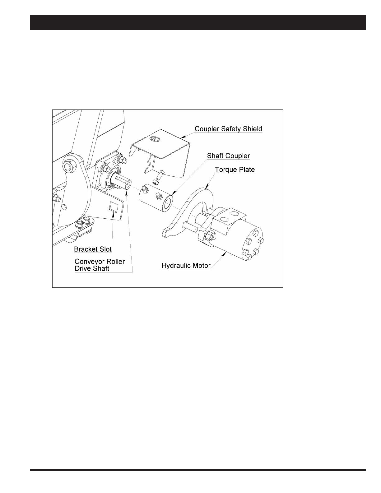
Hydraulic Motor Assembly
1. Install torque plate on hydraulic motor.
2. Install shaft coupler on conveyor roller drive shaft (with 2 set screws at inner end).
3. Install hydraulic motor at outer end of coupler with torque arm in adjacent bracket slot (ensure ¼” x 1” key
on roller shaft and ¼” woodruff key on hydraulic motor shaft are in place). Tighten the 3 set screws and jam
nuts, see Figure 1.
4. Install motor shaft and coupler safety shield.
Figure 1

12
Hydraulic Fittings and Hoses
1. Install hydraulic ttings into motor and cylinder. On the hydraulic cylinder, make sure the restrictor/orice t-
tings (2) are installed between the elbow and hose adapter ttings (both inlet and outlet).
2. Install the 4 quick coupler ttings on the 4 hose ends closest to the tractor.
3. Assemble the hoses onto hydraulic ttings at cylinder and motor. The longer 300” hoses attach to the hydraulic
motor and the 240” hoses attach to the hydraulic cylinder. Tighten the hose ends at the hydraulic motor. At the
cylinder, leave hose connections slightly loose to facilitate bleeding air from the cylinder and the cylinder hoses.
Figure 1
Figure 2
Assembly Instructions

13
Assembly Instructions
Hydraulic Hose Routing
1. Attach hydraulic motor hoses to right side hook arm frame and right side rear lift arm as shown in Figure 1.
Use double clamping with 5/16” bolts (one clamp on top of the other) to space hose clear of the arms.
Figure 1
2. On the hitch A-frame, drill 3/8” holes per dimensions in Figure 2.
Route the 4 hydraulic hoses as shown and clamp to A-frame surface with 5/16” bolts, washers and nuts.
Figure 2
Figure 3

14
Assembly Instructions
Adjustable Arm Stops
1. Install the ‘Clamp On‘ adjustable arm stops on the left & right hook arms as shown in Figure 1.
2. Set adjustment angle to allow lift arms to rest parallel with the at surface of the angle bracket as in Figure 1.
Figure 1

15
Maintenance
Maintenance
For maintenance on bearings and locking collars, grease/lubrication intervals and torque requirements, refer to the
Maintenance section in the 6610 or 6620 Macerator Operator’s Manual.


POWER MERGER 6618
PARTS CATALOGUE

18
39
29
20
2
2
2
24
3
4
35
6
11
11 6
30
25
36
17
18
6
2
11
23
3
2
11
6
6
11
1
44
3
8
37
26
38
6
27
11
6
10
10
11
3
5
28
13
16
31
33
5
32
12
10
27
2
3
2
3
15
11
34
14
19
7
9
2
11
6
611
2
11
64
2
21
3
6
11
222
11 6
2
Conveyor - A66039
Power Merger 6618 - Parts Catalogue
Table of contents
Other AgLand Farm Equipment manuals


Popular Farm Equipment manuals by other brands

Schaffert
Schaffert Rebounder Mounting instructions

Stocks AG
Stocks AG Fan Jet Pro Plus 65 Original Operating Manual and parts list

Cumberland
Cumberland Integra Feed-Link Installation and operation manual

BROWN
BROWN BDHP-1250 Owner's/operator's manual

Molon
Molon BCS operating instructions

Vaderstad
Vaderstad Rapid Series instructions


