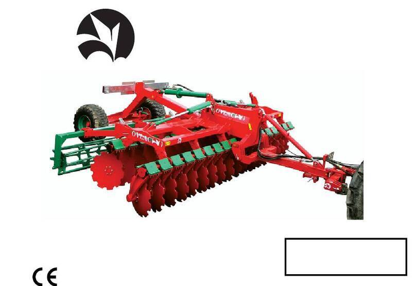
Ovlac MINIVID Guide

1
MINIVID
REVIEW 02-2016
OPERATING INSTRUCIONS AND SPARE
PARTS

2
1. Safety provisions.................................................. 3
2. Description and data technical ........................... 5
3. Protection systems NON STOP........................... 6
4. Set to work............................................................ 6
4.1 Hitching to the tractor .................................. 6
4.2 Alignment...................................................... 7
4.3 Otros adjustments........................................ 8
5. Ploughing depth ................................................... 9
6. Transport and parking.......................................... 9
7. Maintenance........................................................ 10
8. Optional equipment............................................ 11
9. Spare parts.......................................................... 12
This handbook describes the use, maintenance instructions
and spare parts supplied for the indicated plough.
The farming implement known as “plough“ is designed to
work the soil, linked to a tractor with lift and universal 3-point
coupling.
Regular and satisfactory operation together with economic
and long lasting use of the implement depends on compliance
with the instructions given in this handbook. It is, therefore,
advisable to strictly comply with the following instructions in
order to prevent faults which could jeopardise the correct and
long-lasting operation of the implement.
Compliance with the instructions in this handbook is also
important
since the Manufacturer declines all and every
responsibility caused by negligence and failure to comply
with these instructions.
The Manufacturer shall, however, remain at the customer’s
disposal for immediate and thorough assistance together with
anything else that may be required in order to ensure the correct
operation and maximum efficiency of the implement. The
Manufacturer reserves the right to make any modifications and
improvements to the implement, as may be considered
opportune, without being obliged to immediately inform the user.

3
1. SAFETY PROVISIONS
1.-Comply with the instructions given by the danger signals exposed
in this handbook (Fig.1) and affixed to the plough itself.
2.-Operations and adjustments to the implement must always be
carried out when the engine is off and the tractor braked.
3.-It is absolutely forbidden to carry passengers or animals on the
plough.
4.-It is absolutely forbidden for persons without a driving license,
inexpert persons or those in precarious health conditions to drive the
tractor with the plough mounted.
5.-Strictly comply with all the recommended accident preventing
measures described in this handbook.
6.-Assembly of an implement on the tractor will shift the weights on
the axles.
7.-Before starting the tractor and plough, always check that all safety
devices guarding transport and use are in perfect conditions.
8.-The instructions labels affixed to the plough give useful advice on
how to prevent accidents.
9.-Always comply with the highway code in force in your country
when travelling on public roads.
10.-Comply with the maximum permissible weight on the axle of the
tractor, the total adjustable weight, transport regulations and the
highway code.
11.-
Always become familiar with the controls and their operation
before starting work.
12.-
Take the utmost care during the plough coupling and release
phases.
13.-Never ever leave the driving seat whilst the tractor is moving.
14.-
Remember that the road holding, steering and breaking capacity
may be notably influenced by the presence of a mounted implement.
15.-
It is absolutely forbidden to stand within the operative range of the
plough.
16.-
Before leaving the tractor, lower the mounted plough coupled to
the lift unit, stop the engine, engage the hand brake and remove the
ignition key from the control panel.
17.-
The category of the implement coupling pins must correspond to
that of the lift coupling.
18.-
Take care when working close to the lift links. This is a very
dangerous area.
19.-
It is absolutely forbidden to stand between the tractor and the
plough, to manoeuvre the outside lift control.
20.-
Set the control lever of the hydraulic lift to the locked position
during road transport with the plough mounted.
21.-
The spare parts must correspond to the requirements established
by the Manufacturer. Use only genuine spare parts.
22.-
The safety transfers must always be perfectly visible. They must
be kept clean and should be replaced if they become illegible.
Replacements are available on request from your local dealer.
23.-
The instruction manual must be kept for as long as the machine
lasts.

4
Fig.1
(Fig.1) WARNING
Thoroughly read the manual before starting to work
DANGER
Do not handle the plough when lifted, danger of flattening. Keep
safety distance.
DANGER
Damage can be caused by the rotation of the plough. Keep safety
distance.
Be prepared in case of emergency
Have near a first aid kit and an extinguisher. Write down the telephone
numbers of doctors, ambulances and firemen and keep them near the
telephone.
Use suitable clothes
Avoid loose clothes and use suitable equipment of security according to the
type of works. The safe handling of the machine requires all the attention of
the operator.
Don’t put on auricular to listen to the radio during the work with the
machine.

5
2. DESCRIPTION
1. HEADSTOCK
2. FRAME
3. IDENTIFICATION PLATE
4. SET MAXIDISC
5. HYDRAULIC SYSTEM
6. BODIES
7. ARM
8. SECURITY SYSTEM
9. ROLLER
10. SIDE PLATES
REMARK:
The construction number that is
engraved in the identification plate must be
coincident with the number engraved on the
headstock support.
IDENTIFICATION PLATE (3)
4
8
9
1
7
6
5
3
2
9
8
10

6
Rubber deadener
3. PROTECTION SYSTEMS
The different auto-reset protection systems (leafspring / rubber
dampers) work automatically. When finding any obstacle, the system
alllows the tine to trip up and overcome it then returning to its working
position without stopping the tractor.
In this way, all impacts caused by irregularities on the field are
absorbed by the protection system which, therefore, protects all of the
elements on the equipment as well as on the tractor.
Also because of this reason, the auto reset protection systems
decreases the required pull power as they prevent the tractor from
ripping all obstacles that the field may present to an even work.
Note: Ovlac´s auto reset protection systems are set at the
factory at an optimal pressure for average soils.
4. SET TO WORK
4.1 4.1 –HITCHING TO THE TRACTOR
Ovlac equipment are designed to fit the universal 3-point linkage of
any tractor
The cross shaft is supplied in two versions (center-to-center
distance): - Category II 870 mm
- Category III 1.010 mm
Before hitching the equipment, check the following:
- The lower links of the tractor are adjusted at the same height and
length.
- The wheels of the tractor have identical air pressure. This
pressure must be according to the manufacturer´s instructions
- The lower links of the tractor must be centered and allow for a
small oscillation

7
Fig.3
Fig.2
E
4.2 –ALIGNMENT
The plough should always work in line with the tractor. If not, the
tractor will tend to leave the furrow course. Check that lengths A1=A2
(Fig. 2)
Crabbing is corrected automatically in OVLAC ploughs thanks to
their oscillating cross shaft. In ploughs with fix coupling, act on the
drifting-correction turnbuckle (hydraulic in option).
The third point should be linked so that the end linked to the
plough be slightly higher than the one linked to the tractor (Fig. 3)
The third point should always be placed in the oblong hole E (Fig.
3), trying that its length does not hinder it to move while working.

8
Fig.4
Fig.5
Fig.6
CORRECT
INCORRECT
4.3–OTHERS ADJUSTMENTS
The length of the third point should be adjusted so that the frame
works in a parallel position with respect to the field since, if not, the first
bodies would plough at a different depth than the rear ones achieving
an uneven labour (Fig. 4).
For the same reason, check that the beams work vertically to the
field (Fig.5). To achieve this, make sure that the lifting arms of the
tractor are at the same height and act on the adjusting bolts A at the
headstock (Fig. 6).
IMPORTANT:
Care should be taken not to take curves at work,
especially with very wide tools, because the effort lever can cause
serious damage to the structure of the machine.

9
A
Fig.7
5. WORKING DEPTH
The depth of work is regulated by the roller, by means of bolts of
regulation A (Fig 7). In any case the working depth is such that
bushings discs are not left at a suitable distance from land, noting that
they never reach the ground.
6. TRANSPORT
In foldable machines, the side frames must be folded in
hydraulically for transport in order to carry the machine in its
minimum width.

10
7. MAINTENANCE
Retighten all bolts and nuts after the first 8 hours of work, specially
the ones of mouldboards, shares and points. Henceforth, check every 100
hours of work. When putting the plough away, clean and grease
thoroughly the mouldboards to prevent from rusting.
Lubrication: grease the greaser.
Safe maintenance
Be used to the maintenance procedures before carrying out the
works. The working zone must be clean and dry. Don’t carry out any work
of lubrication, repair or adjust with the motor enabled. Keep the hands,
feet and clothes always far from movable components. Turn all the
controls off, to alleviate the pressure. All the components must be in good
state and correctly installed. Repair damages immediately. Change any
worn away or broken pieces. Maintain all the components of the machine
clean of fat, oil and accumulated dirt. Because of being dragged
equipment, disconnect the cable groups of the tractor before making
works of weld in the machine.
Take care of the leaks of high pressure
The fluids that escape of the system can have as much force that
they can penetrate the skin, causing serious injuries. Therefore, it is
essential to leave the system without pressure before relaxing or
disconnecting any pipe and make sure that all the connections and the
hydraulic parts they are well tight before applying pressure to the system.
In order to locate a hydraulic oil leak, use a piece of cardboard that is put
on the connections. Do not approach the hands and the body to a leak of
high pressure. If, in spite of this precaution, it happens an accident, go
immediately to a doctor who should eliminate surgically the fluid within few
hours to avoid gangrene. The doctors who do not have experience in
dealing with these type injuries can go to a specialized medical centre.
Storage of the hydraulic sleeves.
IMPORTANT:
maintain the plugs clean. The abrasive particles, like
the sand or the metallic shaving, can damage the oil seals, shirts and
cylinders, causing internal leaks. Once disconnected of the tractor, make
sure that they are not in contact with the ground

11
8. OPTIONAL EQUIPMENT
The ploughs MCH Ovlac can be equipment with:
1. Extensible roller(Fig.8)
2. Side plates. (Fig.9)
3. Folding headstock. (Fig.10)
Fig.8
Fig.9
Fig.10

12
CONTENT
FRAME ...........................................................................................................13
FIXED MINIVID FRAME..................................................................................15
FOLDING HEADSTOCK ...................................................................................17
HYDRAULIC SYSTEM FOLDING HEADSTOCK.................................................19
SIDE PLATES...................................................................................................20
BODY MCH.....................................................................................................21
BODY..............................................................................................................22
HYDRAULIC SET SYSTEM ...............................................................................24
HYDRAULIC TUBE ..........................................................................................26
ROLLER...........................................................................................................27
9. SPARE PARTS
Spare parts should always be ordered from your dealer and should
always include the following indications:
- Type, model and serial number of the plough.
These data are
punched on the identification plate with which every plough is equipped.
- Code number of the required spare part.
This will be found in the
attached spare parts list.
- Description of the part and required quantity.
- Means of delivery
. Transport expenses shall always be at the
consignor's charge.
- NOTE: The terms Right and Left
indicated on the descriptions, refer to
the plough when viewed from the rear. The spare parts components of
waste equipment, as shares, mouldboards, etc., are considered right if
they are mounted on a body which spills the soil to the right side and
viceversa.
- Note about the warranty
: The orders of spare parts in warranty should
always be clearly specified.
The Manufacturer will always sentence if
the spare parts are warranted in their replacement.
- Moreover, the warranty is suppressed if:
- The plough is repaired without authorisation from the
Manufacturer, or spurious spare parts, and inadequate bolts are
mounted.
-
The plough has been used beyond the specified power limit, or
anomalous manoeuvres and operations have been made.

FIXED FRAME
13

14
FIXED FRAME
REFERENCIA DESCRIPCIÓN REFERENCIA DESCRIPCIÓN
60000083 TORN.EXAG.DIN-931 16* 90 8.8 63002904 BARRA ENG.RAP.CAT-I MINIVID
60000096 TORN.EXAG.DIN-933 20* 50 8.8 77501902 PLACA TORRETA DCH.MINIVID
60000102 TORN.EXAG.DIN-931 20* 80 8.8 77501903 PLACA TORRETA IZQD.MINIVID
60000108 TORN.EXAG.DIN-931 20*110 8.8 ZINC. 77501904 LLANTA UNION TORRETA MINIVID
60000143 TUER.AUTO.DIN-980 16 8.8 ZINC. 77501912 PLACA TORRETA DCH.MINIVID (D/16)
60000146 TUER.AUTO.DIN-980 20 10.9 ZINC. 77501913 PLACA TORRETA IZQD.MINIVID (D/16)
60000160 TUER.EXAG.DIN-934 16 8.8 ZINC. 77511900 BAST.MINIVID-12 FIJA
61000031 ARAND.STANDAR S/BISEL CL-26 ZINC.(50x27x3) 77511901 BAST.MINIVID-14 FIJA
62000002 PASADOR "R" 5 ZINC. 77511902 LLANTA CALZO TORRETA MINIVID
62000004 PASADOR ANILLA 10 ZINC. 77511903 BAST.MINIVID-10 FIJA
63001003 GATILLO ENG.RAP. 90004900 SEP.B.P.32/20* 52mm.
63001005 SEP.TUBO 20*13mm. 90075902 BULON D=25*110mm.3er.PTO.CAT.II ZINC.
63002902 BARRA ENG.RAP.CAT-II MINIVID

FRAME
15

16
FRAME
REFERENCIA DESCRIPCIÓN REFERENCIA DESCRIPCIÓN
60000080 TORN.EXAG.DIN-931 16* 60 8.8 ZINC. 77501903 PLACA TORRETA IZQD.MINIVID
60000083 TORN.EXAG.DIN-931 16* 90 8.8 77501904 LLANTA UNION TORRETA MINIVID
60000096 TORN.EXAG.DIN-933 20* 50 8.8 77501912 PLACA TORRETA DCH.MINIVID (D/16)
60000108 TORN.EXAG.DIN-931 20*110 8.8 ZINC. 77501913 PLACA TORRETA IZQD.MINIVID (D/16)
60000143 TUER.AUTO.DIN-980 16 8.8 ZINC. 77501930 BAST.MINIVID-10
60000143 TUER.AUTO.DIN-980 16 8.8 ZINC. 77501940 BAST.MINIVID-12
60000146 TUER.AUTO.DIN-980 20 10.9 ZINC. 77502901 PAÑO TRAS.DCH.MINIVID-18
60000160 TUER.EXAG.DIN-934 16 8.8 ZINC. 77502902 PAÑO TRAS.IZQD.MINIVID-18
60000373 TUER.AUTO.DIN-985 33/200 8.8 ZINC. 77502903 PAÑO DEL.DCH.MINIVID-18
61000031 ARAND.STANDAR S/BISEL CL-26 ZINC.(50x27x3) 77502904 PAÑO DEL.IZQD.MINIVID-18
62000002 PASADOR "R" 5 ZINC. 77502911 PAÑO TRAS.DCH.MINIVID-14
62000004 PASADOR ANILLA 10 ZINC. 77502912 PAÑO TRAS.IZQD.MINIVID-14
63000148 RASCADOR METALICO 40-50-7/10 77502913 PAÑO DEL.DCH.MINIVID-14
63000149 BARRA CROMADA MECANIZADA D=40*800 F-125 77502914 PAÑO DEL.IZQD.MINIVID-14
63000152 BARRA CROMADA MECANIZADA D=40*550 F-125-TRATADO 77502921 PAÑO TRAS.DCH.MINIVID-10
63000208 GUIA VASTAGO ORKOT 40-45-25 77502922 PAÑO TRAS.IZQD.MINIVID-10
63001003 GATILLO ENG.RAP. 77502923 PAÑO DEL.DCH.MINIVID-10
63001005 SEP.TUBO 20*13mm. 77502924 PAÑO DEL.IZQD.MINIVID-10
63002902 BARRA ENG.RAP.CAT-II MINIVID 77502925 PAÑO TRAS.IZQD.DEL.DCHO.MINIVID-12
63002904 BARRA ENG.RAP.CAT-I MINIVID 77502926 PAÑO TRAS.DCH.DEL.IZQD.MINIVID-12
77501900 BAST.MINIVID-14/18 90004900 SEP.B.P.32/20* 52mm.
77501902 PLACA TORRETA DCH.MINIVID 90075902 BULON D=25*110mm.3er.PTO.CAT.II ZINC.

FOLDING HEADSTOCK
17

18
FOLDING HEADSTOCK
REFERENCIA DESCRIPCIÓN REFERENCIA DESCRIPCIÓN
9000435 TAPON GOMA 120* 60* 6mm. 61000031 ARAND.STANDAR S/BISEL CL-26 ZINC.(50x27x3)
51000005 CILIND.D.E.40-80-250 ROTULAS 62000004 PASADOR ANILLA 10 ZINC.
53000022 ABRAZ.DOBLE D=19mm. 1D19PP 62000011 PASADOR ELAST.DIN-1481 8* 50 ZINC.
53000200 PLACA RFZO.AB.DOBLE 19 GD3D 62000030 PASADOR ELAST.DIN-1481 10* 80 ZINC.
60000098 TORN.EXAG.DIN-931 20* 60 8.8 63000150 CASQ.FRICCION PAP 4030 P10
60000105 TORN.EXAG.DIN-931 20* 90 8.8 70010901 SEP.B.P.36/25* 60mm.
60000108 TORN.EXAG.DIN-931 20*110 8.8 ZINC. 70021930 SOP.LATIG.MINIVID ABATIBLE
60000131 TUER.AUTO.DIN-980 8 8.8 ZINC. 70060903 ARAND.P/BULON PLEG.CH/MCH/DISC
60000142 TUER.AUTO.DIN-980 12 8.8 ZINC. 77511910 PLACA SOP.TORRETA ABATIBLE MINIVID
60000143 TUER.AUTO.DIN-980 16 8.8 ZINC. 77511912 SOP.CIL.TORRETA ABATIBLE MINIVID
60000146 TUER.AUTO.DIN-980 20 10.9 ZINC. 77511913 BULON D=40*395mm.ABAT.MINIVID
60000210 TUER.AUTO.DIN-985 1" SAE 8.8 77511914 BULON D=34,8*86mm.CILIND.ABAT.MINIVID
60000303 TORN.EXAG.DIN-931 8* 65 8.8 ZINC. 77511915 BULON ROSCADO CILIND.ABAT.MINIVID
60000331 TORN.EXAG.DIN-933 20* 50 8.8 ZINC. 77511921 TORRETA ABATIBLE MINIVID (D/16)
60000388 TORN.EXAG.DIN-933 12* 50 8.8 ZINC. 77511922 SOP.CIL.TORRETA ABATIBLE MINIVID 10/14-F
61000031 ARAND.STANDAR S/BISEL CL-26 ZINC.(50x27x3) 90075902 BULON D=25*110mm.3er.PTO.CAT.II ZINC.

REFERENCIA DESCRIPCIÓN
15018907 CASQ. D=45/35*5 SEP.PLEGADOS.CICRO
51000005 CILIND.D.E.40-80-250 ROTULAS
53000001 TORNILLO SIMPLE 3/8 4022
53000006 JUNTA METAL/GOMA 1/2" 11603
53000007 JUNTA METAL/GOMA 3/8" 11602
53000015 UNION MACHO 3/8 4062
53000021 PROTECTOR E.R.MACHO 1/2" ROJO 5029-4PR
53000061 ESFERICO 3/8" TUBO 12mm.LG=205 4002E-205
53000136 LATIG.R2-3/8*1400mm.MF-1/2/TL-3/8
53000284 LATIG.R2-3/8*1500mm.MF-1/2/CTL-3/8
53000418 VALV.OVERCENTER VBCD 3/8 DE-A (V0422)
53000422 ESFERICO 3/8" + UNION TUBO/TUBO 12
53000525 LATIG.R2-3/8*1400mm.MF-1/2/OR-3/8
55000003 ADAPTADOR E.R.FASTER 1/2" 30410108
19
HYDRAULIC SYSTEM FOLDING HEADSTOCK

SIDE PLATES
REFERENCIA DESCRIPCIÓN
60000061 TORN.EXAG.DIN-933 12* 40 8.8 ZINC.
60000142 TUER.AUTO.DIN-980 12 8.8 ZINC.
61000008 ARAND.DIN-125 12 ZINC.
77503900 PLACA SOP.FALDON MINIVID
77503911 FALDON METALICO IZQDO.MINIVID
77503912 FALDON METALICO DCHO.MINIVID
20
Table of contents
Other Ovlac Farm Equipment manuals
Popular Farm Equipment manuals by other brands

Smithco
Smithco Super Star 42-000-E Operator's manual

Kverneland
Kverneland CLG-II-CLC TINES operating manual

Suevia
Suevia KRAZZMAXX IV Mounting and operation instructions

Mayer
Mayer 6160 Big Bale Breaker operating instructions

Frontier
Frontier DH1276 Operator's manual

LOFTNESS
LOFTNESS 61G4 Series Owner's manual and parts book