Remlinger 400 Series Product manual

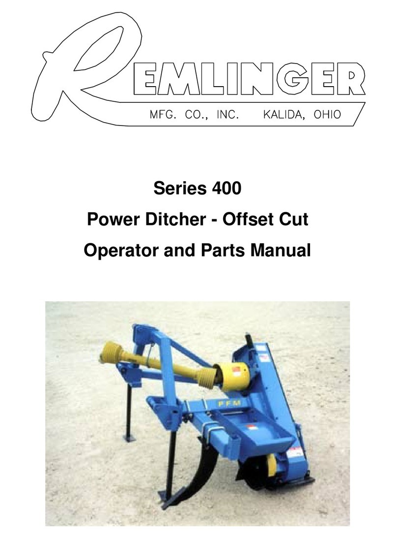
Series 400
Power Ditcher - Center Cut
Operator and Parts Manual

Limited Warranty
Remlinger Manufacturing will warrant all products against defects in material and workmanship
manufactured and sold by it. Warranty will only be granted after examination by appropriate
personnel. This warranty is expressly limited to the replacement or repair of the defective products.
This warranty does not obligate Remlinger Manufacturing to cover cost of labor to replace these
parts. This warranty is in effect for 1 year after purchase.
Remlinger Manufacturing warrants its own products only and cannot be responsible for
damages to equipment on which it is attached or mounted.
Under no circumstances will this Limited Warranty cover any parts or components, in the
opinion Remlinger Manufacturing, that has been subject to negligent handling, misuse, alteration, an
accident, or if repairs have been made with parts other than those obtained from Remlinger
Manufacturing.
Parts claimed to be defective must be returned at the Owner’s expense and returned to
Remlinger Manufacturing for inspection with shipping charges prepaid. Parts found to be defective
will be replaced or repaired and returned promptly free of charge.
For questions or comments about your Remlinger Product contact:
Remlinger Manufacturing Company Inc.
16394 U.S. 224
Kalida, OH 45853
Phone: 1-800-537-7370
Website: www.remlingermfg.com

READ THIS MANUAL carefully to learn how to
assembly, adjust, operate and service your
Remlinger Power Ditcher properly. Failure to
do so could result in personal injury or
equipment damage.
THIS MANUAL SHOULD BE considered a
permanent part of this product and should
remain with it at all times for reference.
ALL REFERENCES to Right-Hand and Left-
Hand are determined by facing the implement
or tool from the rear.
READ AND UNDERSTAND the Limited
Warranty before operating the ditcher. The
Limited Warranty is located on the inside front
cover.
Serial Number for the Power Ditcher is located
on the upper Right-Hand side of the drive
Housing. The number on the PFM metal tag is
the ditcher model number. The number on
the Remlinger decal is the serial number.
Please complete the Registration Form – located on the last page of this manual.
For Your Records
Dealer Purchased From
Name:
Address:
City: State: Zip:
Date Purchased
Model No. (located on the Right-Hand side of the Drive Housing)
Serial No. (located on the Right-Hand side of the Drive Housing)
SERIAL NO:
REMLINGER MFG CO.
000000000

THIS PAGE LEFT BLANK
iviv

vREVISION 040714
Contents
Checklist............................................................................................................................................................1
PREDELIVERYCHECKLIST ................................................................................................................1
DELIVERYCHECKLIST........................................................................................................................1
Safety .............................................................................................................................................................2
RECOGNIZESAFETY INFORMATION.................................................................................................2
UNDERSTANDSIGNALWORDS ..........................................................................................................2
FOLLOWSAFETY INSTRUCTIONS .....................................................................................................2
Safety Cont........................................................................................................................................................3
OPERATESAFELY...............................................................................................................................3
STAY CLEAR OF ROTATING DRIVE LINES..........................................................................................3
LUBRICATETHE DITCHERSAFELY ....................................................................................................3
Operating ...........................................................................................................................................................4
BREAK-IN.............................................................................................................................................4
FIELDOPERATION ..............................................................................................................................4
MAINTAINING ROTORBALANCE.........................................................................................................4
LubricationandMaintenance..............................................................................................................................5
SYMBOLS ............................................................................................................................................5
Q-DBUSHINGTORQUE ......................................................................................................................5
Belt tension setting ............................................................................................................................................6
Troubleshooting ..................................................................................................................................................7
TorqueValues.....................................................................................................................................................8
Storage .............................................................................................................................................................9
END OF SEASON ................................................................................................................................9
BEGINNINGOF SEASON ....................................................................................................................9
Safety Decal Locations .................................................................................................................................... 10
Power Ditcher Assembly repair parts
SN400-440 or higher ........................................................................................................................ 12
Power Ditcher Shank Assembly ....................................................................................................................... 14
PTO SHAFT ASSEMBLY FOR 1 3/8”- 21 SPLINE SHAFT PART # 11300010 (WALTERSCHEID) .................. 16
PTO SHAFT ASSEMBLY FOR 1 3/8”- 6 SPLINE SHAFT PART # 11300011 (WALTERSCHEID) .................... 18
PTO SHAFT ASSEMBLY FOR 1 3/4”- 20 SPLINE SHAFT PART # 11300012 (WALTERSCHEID) .................. 20
PTOSHEAR PINYOKE ASSEMBLYPART# 11300013 (WALTERSCHEID)..................................................... 22
PTO SHAFT ASSEMBLY FOR 1 3/8”- 6 SPLINE SHAFT PART # 11300060 (WEASLER) .............................. 23
PTO SHAFT ASSEMBLY FOR 1 3/8” - 21 SPLINE SHAFT PART # 11300061 (WEASLER) ............................ 24
PTO SHAFT ASSEMBLY FOR 1 3/4” - 20 SPLINE SHAFT PART # 11300062 (WEASLER) ............................ 25

vi
THIS PAGE LEFT BLANK

Check tightness of all external nuts and bolts.
Pay particular attention to those securing the
blades.
Check that all moving parts are working
freely.
Connect PTO, check operation of PTO,
sheave, belt drive and roter. Watch for any
signs of faulty operation, vibration or unusual
sounds. After a period of operation, shut off
tractor engine. Check for loose bolts.
Clean the ditcher and touch up any places
where the paint is nicked or scratched. Be sure
all decals are properly applied and undam-
aged.
Signature of Set-up
Technician______________________________
Advise the customer that he must check the
torque of nuts and bolts after the first 4 hours
of operation.
Tell the customer to record the serial number
of this ditcher in the space provided on page ii
of this manual.
Complete Delivery and Warranty Registration
forms, listing serial number of machine.
Explain Warranty. Have dealer and customer
sign form.
Signature of Set-up
Technician______________________________
Checklist
PREDELIVERY CHECKLIST
After the ditcher has been completely assembled,
inspect it to be sure it is good running order before
delivering it to the customer. Check each item when
found satisfactory or after making the necessary
adjustments.
Ditcher has been assembled properly.
All grease fittings have been lubricated.
Lubricate all lubrication points; be sure all
fittings are taking grease and check all lubri-
cation seals for leakage.
Check drive belt tension and adjust, if neces-
sary.
Date Set Up_____________________________
DELIVERY CHECKLIST
The following check list is a reminder of very
important information which should be conveyed
directly to the customer at the time the ditcher is
delivered. Check off each item as it is fully explained.
Advise the customer that the life expectancy
of this or any other machine depends on
regular lubrication as described in the
operator’s manual.
Give the operator’s manual to your customer
and explain all operating adjustments and
lubrication.
Explain the importance of safe and proper
operation of the machine. Point out decals
warning the operator of the dangers of unsafe
operating procedures and conditions.
Date Delivered________________________
1

SAFETY
RECOGNIZESAFETYINFORMATION
This is the safety-alert symbol. When you see this
symbol on your machine or in this manual, be alert to
the potential for personal injury.
Follow recommended precautions and safe operating practices.
UNDERSTAND SIGNAL WORDS
DANGER: Indicates an imminently hazardous situation that if not
avoided, will result in death or serious injury. This signal word is
to be limited to most extreme situations, typically for machine
components that, for functional purposes, cannot be guarded.
WARNING: Indicates a potentially hazardous situation that, if not
avoided could result in death or serious injury, and includes
hazards that are exposed when guards are removed. It may
also be used to alert against unsafe practices.
CAUTION: Indicates a potentially hazardous situation that, if not
avoided, may result in minor or moderate injury. It may also be
used to alert against unsafe practices
FOLLOW SAFETY INSTRUCTIONS
Carefully read all safety messages in this manual and on your
machine safety signs. Keep safety signs in good condition.
Replace missing or damaged safety signs. Be sure new equip-
ment components and repair parts include the current safety
signs. Replacement safety signs are available from your P F M
dealer.
Learn how to operate the machine and how to use
controls properly. Do not let anyone operate without instruction.
Keep your machine in proper working condition. Unauthorized
modifications to the machine may impair the function and/or
safety and affect machine life.
If you do not understand any part of this manual and need
assistance, contact your P F M dealer. 2

OPERATESAFELY
To avoid bodily injury, keep all power drive safety shields in place.
Operate ditcher with 1000 rpm tractor.
Should excessive vibration occur, disengage tractor PTO shaft
immediatly.
Be sure rotor has stopped completely before checking blades.
Always replace broken, worn or missing blades.
Never ride, or permit others to ride, on the drawbar of the tractor or on
the ditcher.
STAY CLEAR OF ROTATING DRIVE LINES
Entanglement in rotating drive line can cause serious injury or death.
Keep tractor master shield and drive line shields in place at all times.
Make sure rotating shields turn freely.
Wear close fitting clothing. Stop the engine and be sure PTO drive line
is stopped before making adjustments, connections, or cleaning out
PTO driven equipment.
LUBRICATE THE DITCHER SAFELY
Do not clean, lubricate, or adjust the ditcher while it is in motion.
Before servicing or adjusting the ditcher, or removing material from it,
always:
1. Disengage the power.
2. Shut off the engine.
3. Wait until ditcher rotor has stopped rotating.
Safety Cont.
3

BREAK-IN
Before starting the ditcher, lubricate the machine. See Lubrica-
tion and Maintenance Section.
CAUTION: Never operate the ditcher until the power
shaft and other safety shields are in place and
secured, Tighten all nuts and check cotter pins to
see they are properly installed.
FIELD OPERATION
IMPORTANT: The constant striking of rotor blades and
sudden impacts may cause excessive shear pin
breakage. Reduce ditch depth or tractor speed.
Under most conditions, the tractor can be operated at 5 to 11 km/
h (3 to 7 mph) without causing undue wear on the ditcher. Avoid
excessive speeds. Reasonable speeds result in higher productivity.
Various ditching conditions require different ground speeds. Best
results will be obtained by running the tractor at the travel speed
that will meet field conditions or the speed where the smoothest
ditching action results.
IMPORTANT: When operating the ditcher always check
the cutting depth so rotor will spread soil evenly
and consistent.
IMPORTANT: Always operate the ditcher with the tractor
at recommended speed to obtain 1000 rpm on the
tractor PTO shaft.
Operating the tractor at less than recommended PTO rpm will
reduce the blade rotor speed and result in improper ditching.
Where difficult conditions make it necessary to slow down the
ground speed of the tractor, shift to a lower gear, thus keeping the
engine at its rated speed.
Reduce tractor RPM and disengage PTO when raising tractor 3
point hitch. PTO angle should never exceed 20 degrees while
engaged.
IMPORTANT: Do not engage PTO with engine running at
high speed. Doing so may cause undue wear or
possible drive line and/or belt damage.
MAINTAINING ROTOR BALANCE
The rotor on your power ditcher is dynamically balanced and
must be maintained in balance throughout the life of the machine.
CAUTION: Should excessive vibration occur, disengage
the tractor PTO shaft immediately ! Shut off the
tractor and determine the cause of problem.
Correct the problem before operating again. See
Service Section.
Operating
4

Lubrication and Maintenance
SYMBOLS
Lubricate with Multi-Purpose lubricant or an
equivalent SAE multipurpose type grease at
hourly intervals indicated by the symbols.
CAUTION: Do not clean, lubricate, or adjust your
machine while it is in motion.
Clean grease fittings before using grease gun. Replace any
lost or broken fittings immediately.
The application of grease in bearing area is very critical.
Grease approximately four pumps every 50 hours. DO
NOT OVER GREASE
Grease telescoping shaft and universal joints every 50
hours.
Q-D “E” BUSHING TORQUE
Tighten bushing bolts to 60 ft.lbs.
50hrs.
50hrs.
5

Belt Tension Setting
Compress spring to
5 1/2 inches
Centerline between shafts
90 - 100# pressure
Belt should deflect
3/8 inch for center ditcher
1/2 inch for offset ditcher
6

Symptom Problem Solution
Ditch to shallow Adjustment Lower 3 pt on tractor
Retract 3rd link on tractor 3 point
Adjust slide shoe up
Ditch too deep Adjustment Raise 3 pt on tractor
Extend 3rd link on tractor 3 point
Adjust slide shoe down
Non uniform ditching Improper tractor speed Reduce tractor ground speed
or PTO RPM Run PTO at proper RPM
Discharging material not Dirt buildup on discharge spout Clean spout
consistent Ditching to deep in one pass Adjust machine and make two passes
Leaving ridge on Improper tractor ground speed Operate tractor at proper ground speed
discharge side of blade Ditching to deep Adjust machine and make two passes
rotor
Excessive vibration Loss of rotor knife Install new knife
Rotor deformation Straighten the rotor or replace it
Rotor bearing worn out Replace bearing
Belt breakage Incorrect tension Adjust belt for proper tension
Misalignment between sheaves Align sheaves
Residue in the rotor drive Clean and replace shield
Belt slippage Incorrect tension Adjust belt for proper tension
Improper ground speed Reduce ground speed
Ditching to deep in one pass Make two passes
Troubleshooting
7

8
Torque Values
eziS
1edarG2edarG
b
2.5ro,1.5,5edarG2.8ro8edarG
detacirbuL
a
yrD
a
detacirbuL
a
yrD
a
detacirbuL
a
yrD
a
detacirbuL
a
yrD
a
m.Ntf-blm.Ntf-blm.Ntf-blm.Ntf-blm.Ntf-blm.Ntf-blm.Ntf-blm.Ntf-bl
4/17.38.27.45.365.45.75.55.97219 5.3101715.21
61/57.75.501721951110251528182125362
8/3410
17131226172025362443305633664
61/7226182025362442355140725088500157
2/1335224133593760558360110802109051511
61/9846306545765590752109551511571031522061
8/5760558265018753100107
1521512061512061003522
4/302178051011091041042571003522573082524013055004
8/7091041042571091041042571094551526054007005578056
10920120630720920120630725
2704552957605010570031579
-/1-1807400301557307400301557300957605110580541570105810531
-/1-140755245270350755245270350031059056100210502005
100620591
Tighten plastic insert or crimped steel-type lock nut to
approximately 50 percent of the dry torque shown in
the chart, applied to the nut, not to the bolt head.
Tighten toothed or serrated-type lock nuts to the full
torque value.
a“Lubricated” means coated with a lubricant such as
engine oil, or fasteners with phosphate and oil
coatings. “Dry” means plain or zinc plated without
any lubrication.
b Grade 2 applies for hex cap screws (not hex bolts)
up to 152 mm (6-in.) long. Grade 1applies for hex
cap screws over 152 mm (6-in.) long, and for all
other types of bolts and screws of any length.
DO NOT use these values if a different torque value or
tightening procedure is given for a specific application.
Torque values listed are for general use only.Check
tightness of fasteners periodically.
Shear bolts are designed to fail under predetermined
loads. Always replace shear bolts with identical
grade.
Fasteners should be replaced with the same or
higher grade. If higher grade fasteners are used,
these should only be tightened to the strength of the
original.
Make sure fasteners threads are clean and that you
properly start thread engagement. This will prevent
them from failing when tightening.
UNIFIED INCH BOLT AND CAP SCREW TORQUE VALUES

9
Storage
ENDOFSEASON
1. Shelter the power ditcher in a dry place.
2. Clean the power ditcher thoroughly inside and out.
Trash and dirt will draw moisture and cause rust.
3. Thoroughly lubricate the machine according to the
Lubrication Section.
4. Paint all parts from which the paint has been worn.
5. List the replacement parts that will be needed and order
them early. The dealer at this time can expedite delivery
of parts and install them during slack periods avoiding
delays next season.
BEGINNING OF SEASON
1. Lubricate complete machine; this will force any col-
lected moisture out of the bearings (see Lubrication
Section).
2. Tighten all loose bolts, nuts and set screws.
3. Replace blades if worn.
4. Check beltadjustment.
5. Reviewyouroperator’smanual.

10
FM78-400
051216
Safety Decal Locations
METI#TRAPNOITPIRCSEDYTQ
12100042101X4/32-LACEDMFP1
201000421ETALP.ONLAIRES1
34610O.A.S.UNIEDAM-LACED1
45710OTLEBSTRAPGN
IVOM-GNINRAW1
57610O O/W.POTONOD-GNINRAW DRAUG 1
62910ODRAZAH.JBONWORHT-REGNAD1
75.7610O NEEBSAHDRAUG-GNINRAW DEVOM
ER 1
81910O EDALBGNITATOR-REGNAD DRAZAH 2

11
THIS PAGE LEFT BLANK

POWER DITCHER FRAME ASSEMBLY
MODELS 400-10, 400-20 AND 400-30
SERIAL # 400-440 -
12
FM78-400
REVISION051213

POWER DITCHER FRAME B.O.M.
MODELS 400-10, 400-20 AND 400-30
SERIAL # 400-440 -
METI#TRAPNOITPIRCSEDYTQ
171100004EMARFREHCTID1
212100004DIKS1
381100004REVOCEVIRD1
432100004TFAHSROTOR1
562000004ROTOREFINK1
604000004 TFAHSGNIRAEB TROPPUS 1
732000004DNATSEBUT2
891000004DLEIHSOTP1
949000004MSSALAES&DLEIHS1
0101000611EDALBROTOR4
1
142000004TFAHSENILPS1
2191100004TEKSAGREVOC1
3144000501GNLFLP61/51-1GRB1
4101000901E4/3-1GNIHSUB1
5143000901E61/51-1GNI
HSUB1
61610007015790V5/5EVAEHS1
71710007010231V5/5EVAEHS1
8181000221KCAJWERCS1
9143000401AID4/1-1NIPKNILPOT1
0253000401AI
D1NIPKNILPOT1
1233000401NIPTNIOP-3REWOL2
2223000401NIPHCNYL4
3262000901RIAPGNIHSUBRETPADA1
4214000004AID2/1-1NIP1
521210
0401YEKRETTOC1
6238000004TROPPUSOTP1
72040004013X2/1NIPHCTIH2
82310005014/3-1TRESNIGNIRAEB2
92310004014/3-1GNIRRENIATE
R1
03110008016GNIRPS1
METI#TRAPNOITPIRCSEDYTQ
1342100004TLOBRENOISNET1
2302100004DLEIHSROTOR1
3351000811TLEBDEDNAB008XV5/51
435240F4/3REHSAWK
COL4
5391000101CN4/3TUNXEH5
635.2710F2/1-2XCN4/3SCH4
73102000013X2X2/1TLOB-U1
831.3030FCN2/1TUNKCOLYN8
932310F4/1-1XCN2/1
SCH8
047510F2/1-2XCN8/5SCH4
1441100101CN8/5TUNKCOLYN4
24380004012/1-2XQS8/3YEK1
34980004012/1-2XQS2/1YEK1
442.1110F4/11XC
N8/3SCH6
542240F8/3REHSAWKCOL6
642040F8/3REHSAWTALF6
7402.852000012X61/7TLOBEGRC4
847.2030FCN61/7TUNXEH8
940540F61/7REHSA
WRATS8
053040F2/1REHSAWTALF2
153240F2/1REHSAWKCOL4
254.6030F4/3TUNKCOLYNXEH1
355040F4/3REHSAWTALF1
4561000101CN2/1TUNXEH4
5
5062000014/11X2/1TLOBEGRC2
6593000901DI2/1-1GNIHSUB2
7505000501RLLORHPS61/51-1GRB1
85852000012/11X61/7TLOBEGRC4
14000
111MSSAEBUTESAERG2
79000101TUN-U8/36
13 FM78-400
REVISION 090116

POWER DITCHER SHANK ASSEMBLY
MODELS 400-10, 400-20 AND 400-30
14
REVISION030625
Other manuals for 400 Series
1
This manual suits for next models
3
Table of contents
Other Remlinger Farm Equipment manuals
Popular Farm Equipment manuals by other brands

Kerbl
Kerbl buddex 1716 user guide

Dhollandia
Dhollandia DH-RMM 25 installation manual

Rabe
Rabe TURBOSEED PRO Original instructions

Standen
Standen POWAVATOR 150 manual

DuraTech Industries
DuraTech Industries Haybuster Balebuster 2620 Operating Instructions and Parts Reference

AMBIC
AMBIC DIPMIZER quick start guide