Noritake itron Y-Series User manual
DOCUMENT NUMBER :E-M-0001-00
C++ Sample Code Y-Series
1/18 E2−5008−00
Character VFD Module
Y-Series
C++ Sample Code
(Control VFD Module with Host System)
DOCMENT NO. :E-M-0001-00
DATE OF ISSUE : Jan. 29, 2009
REVISION : Jan. 29, 2009
Noritake Co., Inc.
2635 Clearbrook Drive Arlington Height, IL 60005
www.noritake-elec.com
The is the registered trademark of Noritake Itron Corp.
This document is subject to change without notice.

DOCUMENT NUMBER :E-M-0001-00
C++ Sample Code Y-Series
2/18 E2−5008−00
1 Getting Started ....................................................................................................................................3
1.1 Introduction......................................................................................................................................3
1.2 Features of Y-Series VFD Module ..................................................................................................3
1.3 Precautions ......................................................................................................................................3
2 Parallel Communications ...................................................................................................................4
2.1 Sample Circuit..................................................................................................................................4
2.2 Accessories......................................................................................................................................4
2.3 Sample Code ....................................................................................................................................5
3 Serial Communications ......................................................................................................................6
3.1 Asynchronous Serial Communications .........................................................................................6
3.1.1 Sample Circuit ..........................................................................................................................6
3.1.2 Accessories ..............................................................................................................................6
3.1.3 Sample Code.............................................................................................................................7
3.2 Synchronous Serial Communications ...........................................................................................8
3.2.1 Sample Circuit ..........................................................................................................................8
3.2.2 Accessories ..............................................................................................................................8
3.2.3 Sample Code.............................................................................................................................9
4 Sample Command Sets ....................................................................................................................10
4.1 Displaying Characters...................................................................................................................10
4.2 Blinking Characters.......................................................................................................................10
4.3 Underlining Characters .................................................................................................................11
4.4 Highlighting Characters ................................................................................................................11
4.5 User-Definable Font – RAM...........................................................................................................12
4.6 User-Definable Font – Flash ROM ................................................................................................13
4.7 Alternative Magnifed Font.............................................................................................................14
4.8 Alternative 5×7 Font ......................................................................................................................14
4.9 Displaying Symbols (Character Code Type) ...............................................................................15
4.10 Displaynig Symbols (International Font Set)...............................................................................15
4.11 Displayning Firmware Version .....................................................................................................16
4.12 Power Save Mode ..........................................................................................................................16
5 Optical Color Filters ..........................................................................................................................17
6 Revision History ................................................................................................................................18
DOCUMENT NUMBER :E-M-0001-00
C++ Sample Code Y-Series
3/18 E2−5008−00
1 Getting Started
1.1 Introduction
Product image, including color, may differ from actual product appearance.
1.2 Features of Y-Series VFD Module
1.3 Precautions
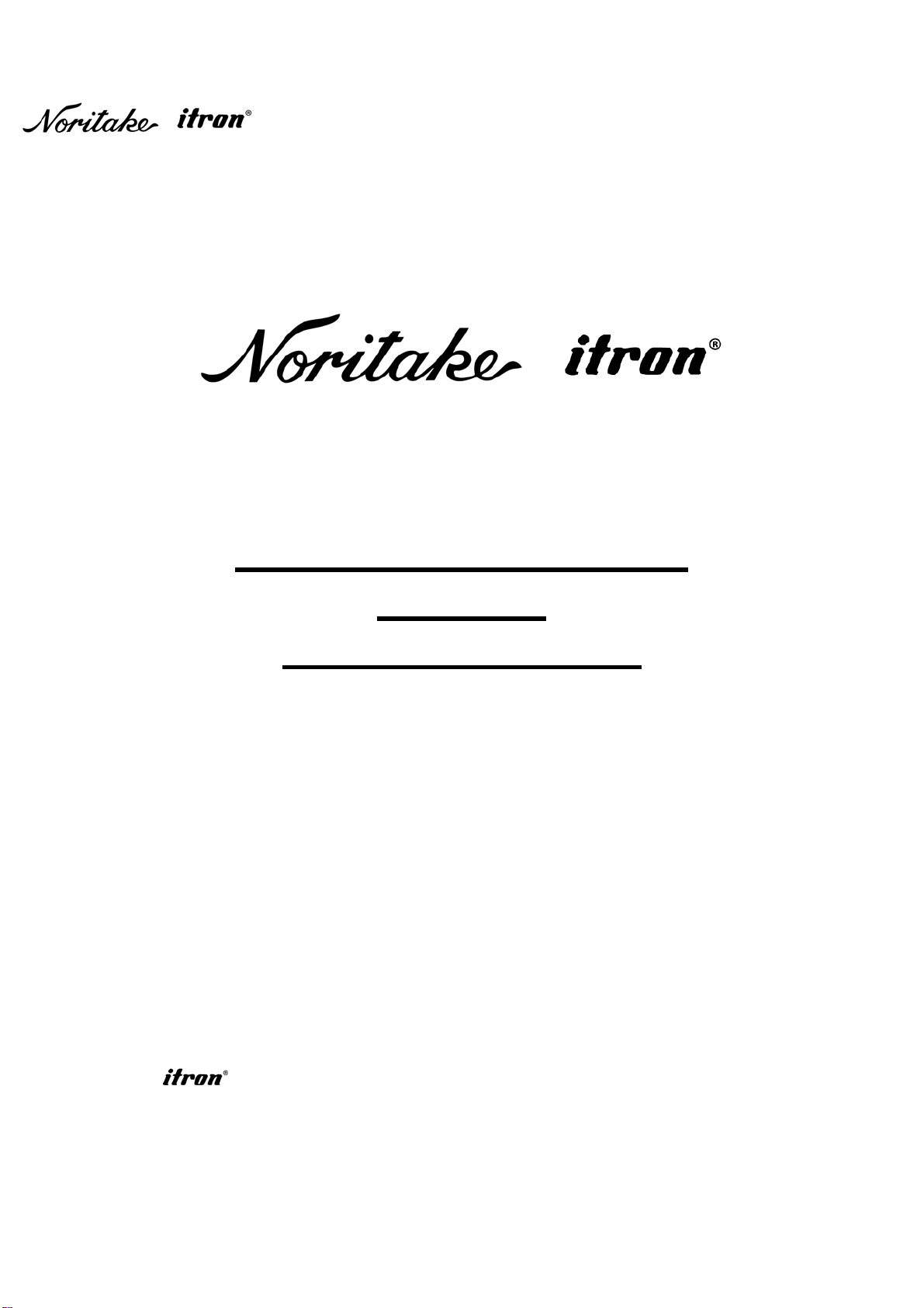
Using this C++ sample code enables you to control the CU24043−Y1A Y-Series Vacuum Florescent Displa
y
module
(Fig. 1-1) with a host system.
Since all the Y-Series VFD modules share the same features and command sets, the starter guide is able to apply to
any Y-Series VFD module with/without minor hardware/software modifications. For further technical inquiries and the
latest Y-Series lineup information, please contact your local sales representative or visit our website at www.noritake-
elec.com/Y-series.htm.
A VFD module is a precision and fragile instrument, so it is necessary to handle it with scrupulous care. Some main
points of handling it are as follows:
•Because the edges of a VFD glass-envelop are not smooth, it is necessar
y
to handle carefull
y
to avoid in
j
uries to
your hands.
•Avoid touching conductive electrical parts, because a VFD module uses high voltage exceeding 30 ~50 volts.
•Do not unplug the power and/or data cables of a VFD module durin
g
operatin
g
condition because unrecoverable
damage may result.
•A VFD module needs electrostatic free packa
g
in
g
and protection from electrostatic char
g
es durin
g
handlin
g
and
usage.
Before open the package, please refer to your specific module specification “Notice for the Cautious Handlin
g
VFD
Modules”.
Fig. 1-1
The Y-Series is a 5×8 matrix character
V
FD module desi
g
ned to reduce development cost and time. The module
requires only a single 5VDC power supply and works with virtually any host system as long as one of the followin
g
interfaces is available:
•8-bit parallel 5VDC CMOS Level (CUXXXXX−Y1A model and CUXXXXX−Y100 model)
•Synchronous serial 5VDC CMOS Level (CUXXXXX−Y1A model)
•Asynchronous serial 5VDC CMOS Level (CUXXXXX−Y1A model)
•Asynchronous serial RS232 Level (CUXXXXX−Y100 model)
With simple hex-code command sets, the module provides various functions such as hi
g
hli
g
htin
g
characters, blinkin
g
characters, underlin
g
characters, font ma
g
nification, etc. which conventional character displa
y
s do not have.
Additionally, various fonts including basic ASCII font, international font, symbols and user-definable font can be easil
y
displayed.
DOCUMENT NUMBER :E-M-0001-00
C++ Sample Code Y-Series
4/18 E2−5008−00
2 Parallel Communications
2.1 Sample Circuit
2.2 Accessories
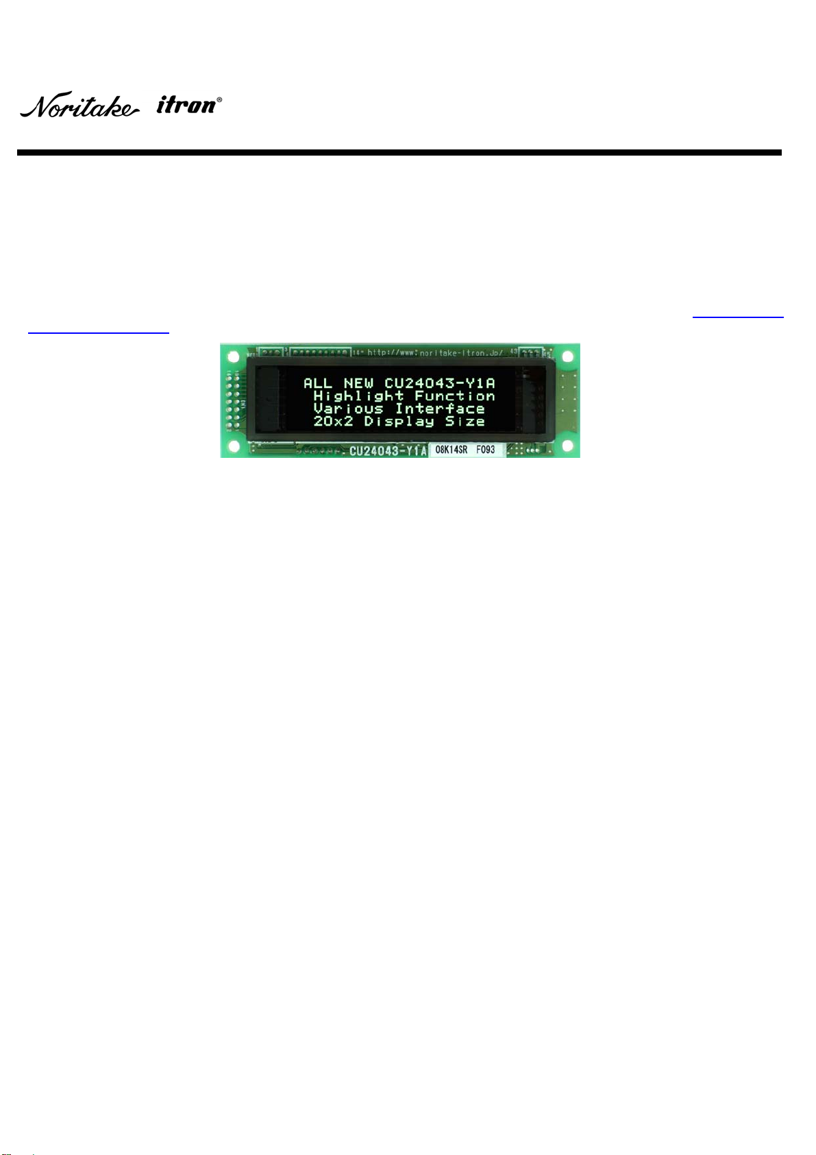
The VFD module has an 8-bit parallel 5VDC CMOS level
interface. Fig. 2-1 shows a block diagram of the parallel
communication. Refer to
y
our specific module
specification “Parallel Interface”.
Pin 14
Pin 12
Pin 10
Pin 8
Pin 6
Pin 4
Pin 2
Pin 13
Pin 11
Pin 9
Pin 7
Pin 5
Pin 3
Pin 1
Host
System VFD
Module
PBUSY
/WR
D0−D7
Fig. 2-2
Fig. 2-1
Fig. 2-2 shows a sample circuit containing the PIC microcontroller PIC16F877.
Noritake provides these parallel interface accessories. For further information, please contact
y
our local sales
representative.
Fig. 2-3: 14-Wire Cable Fig. 2-4: 14-Pin
Male Header Fig. 2-5: 14-Pin
Female Header
Note: This figure shows the pin configuration of the
CU24043−Y1A. Please make sure the pin
confi
g
uration of
y
our specific module before
connecting.
PIN CONFIGURATION
OF CU24043−Y1A.
Actual VFD module
ma
y
have different pin
configuration.

DOCUMENT NUMBER :E-M-0001-00
C++ Sample Code Y-Series
5/18 E2−5008−00
2.3 Sample Code
Example 2-1 is a C++ sample code for Fig. 2-2 (8-bit Parallel Interface
)
. It initializes the module and executes a
demonstration
(
displa
y
in
g
all Common Font Set characters
)
. The code has been compiled with the CCS C++ Complier
only and may need minor editing to work with other compilers. Refer to your specific module specification “Parallel
Interface”.
#include <16F877.h> //for PIC16F877
#fuses HS,NOWDT,NOPROTECT,PUT,BROWNOUT,NOLVP
#use delay(clock = 20000000) //for 20MHz clock
#use fast_io(B) //use B port fast I/O
#use fast_io(C) //use C port fast I/O
//define output ports
#define D0 PIN_B0
#define D1 PIN_B1
#define D2 PIN_B2
#define D3 PIN_B3
#define D4 PIN_B4
#define D5 PIN_B5
#define D6 PIN_B6
#define D7 PIN_B7
#define PBUSY PIN_C6
#define WR PIN_C7
//Variable declaration
int n, data;
//Prototype of functions
void executing_demo( );
void parallel_out(int data);
void main( )
{
//Initialize a PIC and a display.
delay_ms(1000); //warm up delay
set_tris_b(0x00); //B0 ~ B7 = output
set_tris_c(0x40); //C6 = input, C7 = output
output_b(0x00); //B0 ~ B7 = 0
output_high(WR); //WR = 1
parallel_out(0x1B); //display initialization
parallel_out(0x40);
//Execute a demonstration.
executing_demo( );
}
void executing_demo( )
{
for(data = 0x20; data <= 0x7F; data++)
parallel_out(data);
}
void parallel_out(int data)
{
//if PBUSY == 1, wait until PBUSY == 0
while(input(PBUSY) == 1)
{
}
output_low(WR); //WR = 0
if((data & 0x01) == 0x01) //if bit_0 (LSB) == 1, D0 = 1
output_high(D0);
else //if bit_0 (LSB) == 0, D0 = 0
output_low(D0);
if((data & 0x02) == 0x02) //if bit_1 == 1, D1 = 1
output_high(D1);
else //if bit_1 == 0, D1 = 0
output_low(D1);
if((data & 0x04) == 0x04) //if bit_2 == 1, D2 = 1
output_high(D2);
else //if bit_2 == 0, D2 = 0
output_low(D2);
if((data & 0x08) == 0x08) //if bit_3 == 1, D3 = 1
output_high(D3);
else //if bit_3 == 0, D3 = 0
output_low(D3);
if((data & 0x10) == 0x10) //if bit_4 == 1, D4 = 1
output_high(D4);
else //if bit_4 == 0, D4 = 0
output_low(D4);
if((data & 0x20) == 0x20) //if bit_5 == 1, D5 = 1
output_high(D5);
else //if bit_5 == 0, D5 = 0
output_low(D5);
if((data & 0x40) == 0x40) //if bit_6 == 1, D6 = 1
output_high(D6);
else //if bit_6 == 0, D6 = 0
output_low(D6);
if((data & 0x40) == 0x80) //if bit_7 (MSB) == 1, D7 = 1
output_high(D7);
else //if bit_7 (MSB) == 0, D7 = 0
output_low(D7);
output_high(WR); //WR = 1 to clock in data
delay_us(20); //wait 20us
}
Example 2-1
DOCUMENT NUMBER :E-M-0001-00
C++ Sample Code Y-Series
6/18 E2−5008−00
3 Serial Communications
3.1 Asynchronous Serial Communications
3.1.1 Sample Circuit
3.1.2 Accessories
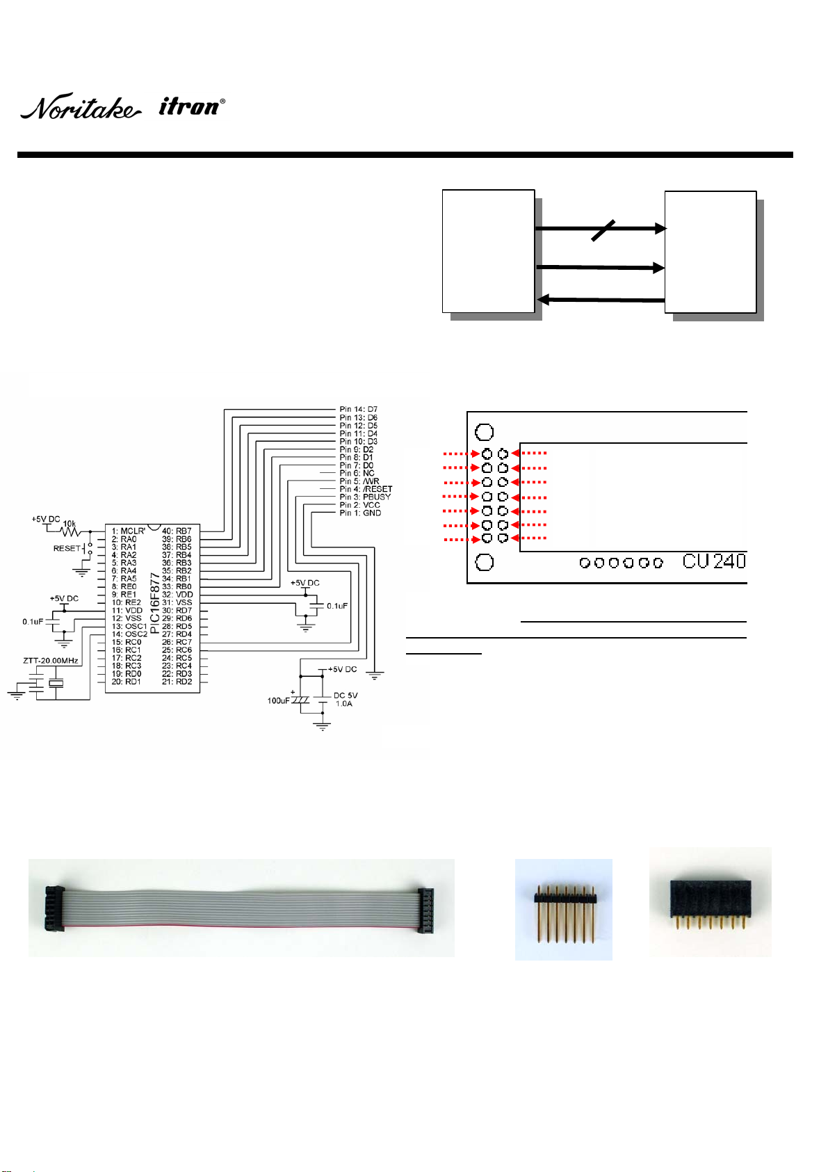
Fig. 3-1 shows a block dia
g
ram of the as
y
nchronous serial
interface. The asynchronous mode is the default settin
g
,
so chan
g
in
g
j
umper settin
g
is not required to use this
mode. One of the four baud rates
(
9600 bps, 19,200 bps,
38,400 bps or 115,200 bps
)
is selectable with Jumper 0
and 1. The default baud rate is 38,400 bps. Refer to
y
our
specific module specification “Serial Interface” and
“Jumper Setting”.
The CUXXXXX−Y1A model has an as
y
nchronous/s
y
nchronous serial 5VDC CMOS level interface. Either the
asynchronous or synchronous mode is selectable by the jumper setting. The CUXXXXX−Y100 model has an
asynchronous serial RS232 level interface.
Pin 1
Pin 2
Pin 3
Pin 4
Pin 5
Pin 6
Host
System VFD
Module
SBUSY
SIN
Fig. 3-1
Fig. 3-2
Fig. 3-2 shows a sample circuit containing the PIC microcontroller PIC16F877.
Noritake provides these serial interface accessories. For further information, please contact
y
our local sales
representative.
Note: This fi
g
ure shows the pin confi
g
uration of the
CU24043−Y1A. Please make sure the pin
confi
g
uration of
y
our specific module before
connecting.
Fig. 3-4:
6-Pin
Straight
Header
W/Lock
Fig. 3-5:
6-Pin
Right-Angle
Header
W/Lock
Fig. 3-6:
6-Pin
Header
Fig. 3-3: 6-Wire Cable
PIN CONFIGURATION
OF CU24043−Y1A.
Actual VFD module
ma
y
have different pin
configuration.

DOCUMENT NUMBER :E-M-0001-00
C++ Sample Code Y-Series
7/18 E2−5008−00
3.1.3 Sample Code
Example 3-1 is a C++ sample code for Fig. 3-2
(
As
y
nchronous Serial Interface
)
. It initializes the module and executes
a demonstration
(
displa
y
in
g
all Common Font Set characters
)
. The code has been compiled with the CCS C++
Complier only and may need minor editing to work with other compilers. Refer to
y
our specific module specification
“Serial Interface” and “Jumper Setting”.
#include <16F877.h> //for PIC16F877
#fuses HS,NOWDT,NOPROTECT,PUT,BROWNOUT,NOLVP
#use delay(clock = 20000000) //for 20MHz clock
//use EUSART module, baud rate = 38,400bps, format: Start (1bit) + Data (8bit) + Stop (1bit)
#use rs232(BAUD = 38400, XMIT = PIN_C6, RCV = PIN_C7)
#use fast_io(D) //use D port fast I/O
//define output ports
#define SBUSY PIN_D3
//Variable declaration
int n, data;
//Prototype of functions
void executing_demo( );
void asynchro_out(int data);
void main( )
{
//Initialize a PIC and a display.
delay_ms(1000); //warmup delay
set_tris_d(0x04); //D3 = input
asynchro_out(0x1B); //display initialization
asynchro_out(0x40);
//Execute a demonstration.
executing_demo( );
}
void executing_demo( )
{
for(data = 0x20; data <= 0x7F; data++)
asynchro_out(data);
}
void asynchro_out(int data)
{
//if SBUSY == 1, wait until SBUSY == 0
while(input(SBUSY) == 1)
{
}
putc(data); //send 8-bit Asynchronous Serial data
}
Example 3-1

DOCUMENT NUMBER :E-M-0001-00
C++ Sample Code Y-Series
8/18 E2−5008−00
3.2 Synchronous Serial Communications
3.2.1 Sample Circuit
3.2.2 Accessories
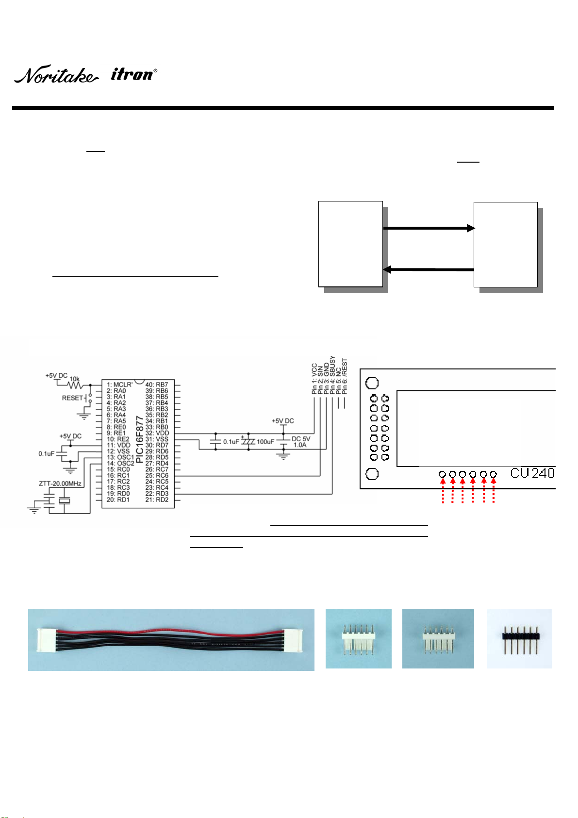
Fig. 3-7 shows a block dia
g
ram of the s
y
nchronous serial
5VDC CMOS level interface. The s
y
nchronous mode is not
a default setting, so changing jumper setting is required.
Refer to your specific module specification “Serial
Interface” and “Jumper Setting”.
Pin 1
Pin 2
Pin 3
Pin 4
Pin 5
Pin 6
Host
System VFD
Module
SBUSY
SCK
SIN
Fig. 3-7
Fig. 3-8
Noritake provides these serial interface accessories. For further information, please contact
y
our local sales
representative.
Fig. 3-9: 6-Wire Cable Fig. 3-10:
6-Pin
Straight
Header
W/Lock
Fig. 3-11:
6-Pin
Right-Angle
Header
W/Lock
Fig. 3-12:
6-Pin
Header
Fig. 3-8 shows a sample circuit containing a PIC microcontroller.
PIN CONFIGURATION
OF CU24043−Y1A.
Actual VFD module
ma
y
have different pin
configuration.
Note: This figure shows the pin confi
g
uration of the
CU24043−Y1A. Please make sure the pin
confi
g
uration of
y
our specific module before
connecting.

DOCUMENT NUMBER :E-M-0001-00
C++ Sample Code Y-Series
9/18 E2−5008−00
3.2.3 Sample Code
Example 3-2 is a C++ sample code for Fig. 3-8
(
S
y
nchronous Serial Interface
)
. It initializes the module and executes a
demonstration
(
displa
y
in
g
all Common Font Set characters
)
. The code has been compiled with the CCS C++
Complier only and may need minor editing to work with other compilers. Refer to your specific module specification
“Serial Interface” and “Jumper Setting”.
#include <16F877.h> //for PIC16F877
#fuses HS,NOWDT,NOPROTECT,PUT,BROWNOUT,NOLVP
#use delay(clock = 20000000) //for 20MHz clock
#use fast_io(C) //use C port fast I/O
//define output ports
#define REST PIN_C4
#define CLK PIN_C5
#define SBUSY PIN_C6
#define SIN PIN_C7
//Variable declaration
int n, data;
//Prototype of functions
void executing_demo( );
void synchro_out(int data);
void main( )
{
//Initialize a PIC and a display.
delay_ms(1000); //warmup delay
set_tris_c(0x40);
//C4 = output, C5 = output, C6 = input, C7 = output
output_low(SIN); //SIN = 0
output_high(CLK); //CLK = 1
output_low(REST); //REST = 0, display reset
delay_us(1000); //wait 1ms
output_high(REST); //REST = 1
//Execute a demonstration.
executing_demo( );
}
void executing_demo( )
{
for(data = 0x20; data <= 0x7F; data++)
synchro_out(data);
}
void synchro_out(int data)
{
//if SBUSY == 1, wait until SBUSY == 0
while(input(SBUSY) == 1)
{
}
output_low(CLK); //CLK = 0
if((data & 0x01) == 0x01) //if bit_0 (LSB) == 1, D0 = 1
output_high(SIN);
else //if bit_0 (LSB) == 0, D0 = 0
output_low(SIN);
output_high(CLK); //CLK = 1 to clock in data
output_low(CLK);
if((data & 0x02) == 0x02) //if bit_1 == 1, D1 = 1
output_high(SIN);
else //if bit_1 == 0, D1 = 0
output_low(SIN);
output_high(CLK); //CLK = 1 to clock in data
output_low(CLK);
if((data & 0x04) == 0x04) //if bit_2 == 1, D2 = 1
output_high(SIN);
else //if bit_2 == 0, D2 = 0
output_low(SIN);
output_high(CLK); //CLK = 1 to clock in data
output_low(CLK);
if((data & 0x08) == 0x08) //if bit_3 == 1, D3 = 1
output_high(SIN);
else //if bit_3 == 0, D3 = 0
output_low(SIN);
output_high(CLK); //CLK = 1 to clock in data
output_low(CLK);
if((data & 0x10) == 0x10) //if bit_4 == 1, D4 = 1
output_high(SIN);
else //if bit_4 == 0, D4 = 0
output_low(SIN);
output_high(CLK); //CLK = 1 to clock in data
output_low(CLK);
if((data & 0x20) == 0x20) //if bit_5 == 1, D5 = 1
output_high(SIN);
else //if bit_5 == 0, D5 = 0
output_low(SIN);
output_high(CLK); //CLK = 1 to clock in data
output_low(CLK);
if((data & 0x40) == 0x40) //if bit_6 == 1, D6 = 1
output_high(SIN);
else //if bit_6 == 0, D6 = 0
output_low(SIN);
output_high(CLK);
output_low(CLK);
if((data & 0x80) == 0x80) //if bit_7 (MSB) == 1, D7 = 1
output_high(SIN);
else //if bit_7 (MSB) == 0, D7 = 0
output_low(SIN);
output_high(CLK); //CLK = 1 to clock in data
delay_us(17); //wait 17us
}
Example 3-2
DOCUMENT NUMBER :E-M-0001-00
C++ Sample Code Y-Series
10/18 E2−5008−00
4 Sample Command Sets
4.1 Displaying Characters
4.2 Blinking Characters
Fig. 4-1
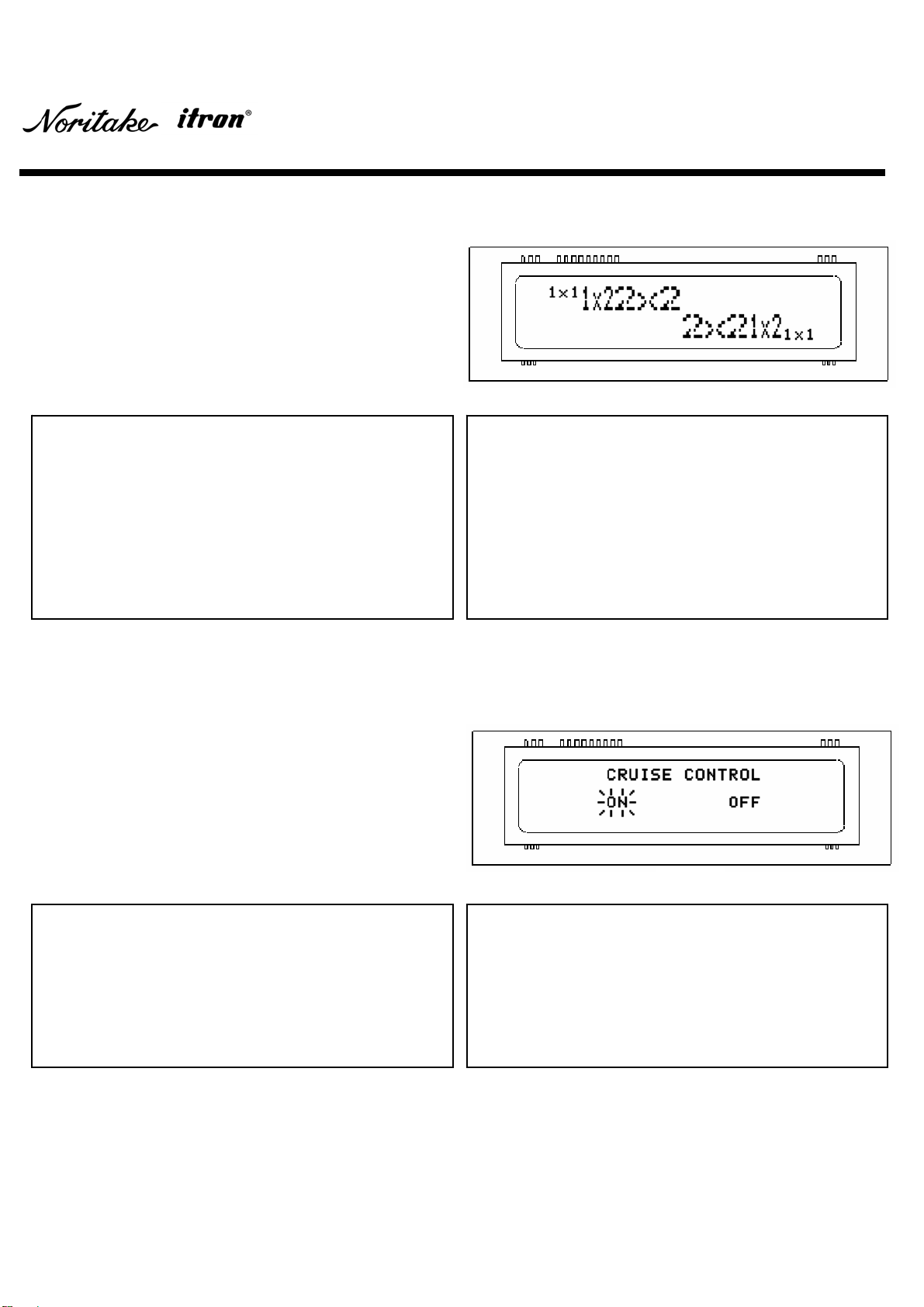
The VFD module contains three font sizes: a 1×1 re
g
ular
font size
(
5×8 pixel
)
, a 1×2 ma
g
nified font size
(
5×16 pixel
)
and a 2×2 ma
g
nified font size
(
10×16 pixel
)
. A character is
displa
y
ed at the current cursor position, and the position
is set b
y
usin
g
‘Cursor set’ command. The cursor position
is incremented after each character is displayed. Refer to
your specific module specification “Display Area-End of
Line Behavior”. The following command set displays
characters shown in Fig. 4-1.
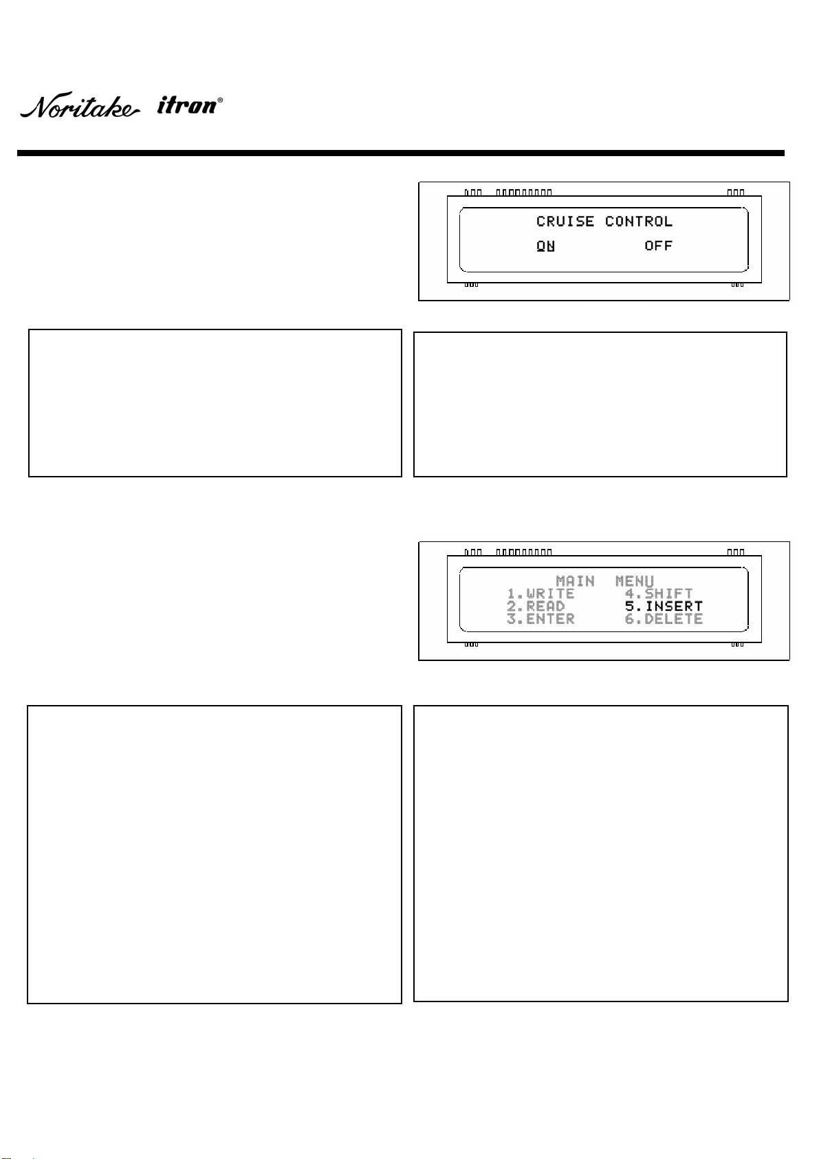
The VFD module features an individual matrix (character
)
blinking function. The following command set displays
characters shown in Fig. 4-2.
Fig. 4-2
void displaying_characters( )
{
const int command_set [60] = {
0x31, 0x78, 0x31, //Character Code
0x1F, 0x28, 0x67, 0x40, 0x01, 0x02, //Character Size
0x31, 0x78, 0x32, //Character Code
0x1F, 0x28, 0x67, 0x40, 0x02, 0x02, //Character Size
0x32, 0x78, 0x32, //Character Code
0x1F, 0x24, 0x0C, 0x00, 0x02, 0x00, //Cursor Position
0x1F, 0x28, 0x67, 0x40, 0x02, 0x02, //Character Size
0x32, 0x78, 0x32, //Character Code
Example 4-1
void blinking_characters( )
{
const int command_set [41] = {
0x1F, 0x24, 0x05, 0x00, 0x00, 0x00, //Cursor Position
0x43, 0x52, 0x55, 0x49, 0x53, 0x45, 0x20, 0x43, 0x4f,
0x4E, 0x54, 0x52, 0x4f, 0x4C, //Character Code
0x1F, 0x24, 0x05, 0x00, 0x02, 0x00, //Cursor Position
0x1B, 0x42, //Blink Character
0x4F, 0x4E, //Character Code
Example 4-2
0x1F, 0x28, 0x67, 0x40, 0x01, 0x02, //Character Size
0x31, 0x78, 0x32, //Character Code
0x1F, 0x24, 0x15, 0x00, 0x03, 0x00, //Cursor Position
0x1F, 0x28, 0x67, 0x40, 0x01, 0x01, //Character Size
0x31, 0x78, 0x31}; //Character Code
for(n = 0; n < 60; n++)
{
data = command_set [n];
parallel_out (data);
}
}
0x1F, 0x24, 0x10, 0x00, 0x02, 0x00, //Cursor Position
0x1B, 0x41, //Blink Character
0x4F, 0x46, 0x46}; //Cursor Position
for(n = 0; n < 41; n++)
{
data = command_set [n];
parallel_out (data);
}
}
DOCUMENT NUMBER :E-M-0001-00
C++ Sample Code Y-Series
11/18 E2−5008−00
4.3 Underlining Characters
4.4 Highlighting Characters
The
V
FD module features the individual character
brightness control function. Individual character
brightness is a relative value of over all displa
y
brightness. In order to make highlighted characters
conspicuous, higher over all displa
y
bri
g
htness and lower
non-hi
g
hli
g
hted character bri
g
htness are recommended.
The following command set displays characters shown in
Fig. 4-4.
The VFD module features an individual matrix
(
character
)
underlining function. The following command set displays
characters shown in Fig. 4-3.
Fig. 4-4
void underlining_characters( )
{
const int command_set [41] = {
0x1F, 0x24, 0x05, 0x00, 0x00, 0x00, //Cursor Position
0x43, 0x52, 0x55, 0x49, 0x53, 0x45, 0x20, 0x43, 0x4f,
0x4E, 0x54, 0x52, 0x4f, 0x4C, //Character Code
0x1F, 0x24, 0x05, 0x00, 0x02, 0x00, //Cursor Position
0x1B, 0x55, //Underline Character
0x4F, 0x4E, //Character Code
Example 4-3
void highlighting_characters( )
{
const int command_set [123] = {
0x1F, 0x58, 0x08, //Display Brightness
0x1F, 0x24, 0x07, 0x00, 0x00, 0x00, //Cursor Position
0x1F, 0x28, 0x67, 0x50, 0x03, 0x00, 0x00,
//Character Brightness
0x4D, 0x41, 0x49, 0x4E, //Character Code
0x1F, 0x24, 0x0D, 0x00, 0x00, 0x00, //Cursor Position
0x4D, 0x45, 0x4E, 0x55, //Character Code
0x1F, 0x24, 0x02, 0x00, 0x01, 0x00, //Cursor Position
0x31, 0x2E, 0x57, 0x52, 0x49, 0x54, 0x45,
//Character Code
0x1F, 0x24, 0x0E, 0x00, 0x01, 0x00, //Cursor Position
0x34, 0x2E, 0x53, 0x48, 0x49, 0x46, 0x54,
//Character Code
0x1F, 0x24, 0x02, 0x00, 0x02, 0x00, //Cursor Position
0x32, 0x2E, 0x52, 0x45, 0x41, 0x44, //Character Code
0x1F, 0x24, 0x0E, 0x00, 0x02, 0x00, //Cursor Position
Example 4-4
Fig. 4-3
0x1F, 0x28, 0x67, 0x50, 0x08, 0x00, 0x00,
//Character Brightness
0x35, 0x2E, 0x49, 0x4E, 0x53, 0x45, 0x52, 0x54,
//Character Code
0x1F, 0x24, 0x02, 0x00, 0x03, 0x00, //Cursor Position
0x1F, 0x28, 0x67, 0x50, 0x03, 0x00, 0x00,
//Character Brightness
0x33, 0x2E, 0x45, 0x4E, 0x54, 0x45, 0x52,
//Character Code
0x1F, 0x24, 0x0E, 0x00, 0x03, 0x00, //Cursor Position
0x36, 0x2E, 0x44, 0x45, 0x4C, 0x45, 0x54, 0x45};
//Character Code
for(n = 0; n < 123; n++)
{
data = command_set [n];
parallel_out (data);
}
}
0x1F, 0x24, 0x10, 0x00, 0x02, 0x00, //Cursor Position
0x1B, 0x57, //Underline Character
0x4F, 0x46, 0x46}; //Character Code
for(n = 0; n < 41; n++)
{
data = command_set [n];
parallel_out (data);
}
}
DOCUMENT NUMBER :E-M-0001-00
C++ Sample Code Y-Series
12/18 E2−5008−00
4.5 User-Definable Font – RAM
DEFINING FONTS (Fig. 4-6 and Fig. 4-7)
DISPLAYING CHARACTERS (Fig. 4-5)
B7 (MSB) B6 B5 B4 B3 B2 B1 B0 (LSB)
BYTE 1 P8 P7 P6 P5 P4 P3 P2 P1
BYTE 2 P16 P15 P14 P13 P12 P11 P10 P9
BYTE 3 P24 P23 P22 P21 P20 P19 P18 P17
BYTE 4 P32 P31 P30 P29 P28 P27 P26 P25
BYTE 5 P40 P39 P38 P37 P36 P35 P34 P33
Fig. 4-6 Fig. 4-7 Table 4-1
void defining_ram_user_font( )
{
const int command_set [17] = {
0x1B, 0x26, 0x01, //Define RAM User Font
0x50, //Starting Character Code
0x51, //Ending Character Code
0x05, //The Number of bytes for a Character
0x00, //BYTE 1 DATA
0x62, //BYTE 2 DATA
0xCE, //BYTE 3 DATA
0x31, //BYTE 4 DATA
0x04, //BYTE 5 DATA
Example 4-5
Fig. 4-5
Each bit value is logic level one, in Fig. 4-6, Fig. 4-7 and Table 4-1, if a
pixel is ON, whereas the value is logic level zero if a pixel is OFF. The
character code address location of Fig. 4-6 and Fig. 4-7 are 50h and 51h
respectively in this example.
0x05, //The Number of bytes for a Character
0x82, //BYTE 1 DATA
0x24, //BYTE 2 DATA
0xA5, //BYTE 3 DATA
0x12, //BYTE 4 DATA
0x11}; //BYTE 5 DATA
for(n = 0; n < 17; n++)
{
data = command_set [n];
parallel_out (data);
}
}
User-definable font – RAM is stored
(
maximum 16
characters) and displayed in a horizontal orientation.
A
user-definable font can be stored into RAM location 20h to
FFh. Example 4-5 defines two symbols (Fig. 4-6 and Fig. 4-
7), and Example 4-6 displays the symbols and some
characters (Fig. 4-5). An initialization of the module clears
all definded RAM user fonts.
void displaying_ram_user_font( )
{
const int command_set [42] = {
0x1F, 0x24, 0x05, 0x00, 0x00, 0x00, //Cursor Position
0x53, 0x50, 0x45, 0x41, 0x4B, 0x45, 0x52, 0x20, 0x56,
0x4F, 0x4C, 0x55, 0x4D, 0x45,
//Character Code
0x1B, 0x25, 0x01, //Enable RAM User Font
0x1F, 0x24, 0x0A, 0x00, 0x02, 0x00, //Cursor Position
0x50, 0x51, //Character Code
Example 4-6
0x1B, 0x25, 0x00, //Disable RAM User Font
0x1F, 0x24, 0x0D, 0x00, 0x02, 0x00, //Cursor Position
0x34, 0x35}; //Character Code
for(n = 0; n < 42; n++)
{
data = command_set [n];
parallel_out (data);
}
}

DOCUMENT NUMBER :E-M-0001-00
C++ Sample Code Y-Series
13/18 E2−5008−00
4.6 User-Definable Font – Flash ROM
DEFINING FONTS (Fig. 4-9 and Fig. 4-10)
DISPLAYING CHARACTERS (Fig. 4-8)
B7 (MSB) B6 B5 B4 B3 B2 B1 B0 (LSB)
BYTE 1 P8 P7 P6 P5 P4 P3 P2 P1
BYTE 2 P16 P15 P14 P13 P12 P11 P10 P9
BYTE 3 P24 P23 P22 P21 P20 P19 P18 P17
BYTE 4 P32 P31 P30 P29 P28 P27 P26 P25
BYTE 5 P40 P39 P38 P37 P36 P35 P34 P33
Each bit value is logic level one, in Fig. 4-9, Fig. 4-10 and Table 4-2, if a
pixel is ON, whereas the value is logic level zero if a pixel is OFF. The
character code address location of Fig. 4-9 and Fig. 4-10 are 20h and
21h res
p
ecti
v
el
y
in this exam
p
le.
Fig. 4-9 Fig. 4-10
Table 4-2
Fig. 4-8
void defining_rom_user_font( )
{
const int command_set [1137] = {
0x1F, 0x28, 0x65, 0x01, 0x49, 0x4E, //User Setup Mode
0x1F, 0x28, 0x65, 0x14, //Define ROM User Font
0x00, //BYTE 1 DATA
0x62, //BYTE 2 DATA
0xCE, //BYTE 3 DATA
0x31, //BYTE 4 DATA
0x04, //BYTE 5 DATA
0x82, //BYTE 1 DATA
0x24, //BYTE 2 DATA
0xA5, //BYTE 3 DATA
Example 4-7
User-definable font – Flash ROM is stored
(
224 characters:
20h ~ FFh
)
and displa
y
ed in a horizontal orientation. All
224 character data has to be defined at once, so dumm
y
blank data is stored in the unused memory space. Example
4-7 defines two symbols (Fig. 4-9 and Fig. 4-10
)
, and
Example 4-8 displa
y
s the s
y
mbols and some characters
(Fig. 4-8). An initialization of the module does not clear
defined ROM user fonts.
0x12, //BYTE 4 DATA
0x11, //BYTE 5 DATA
0x00, 0x00, 0x00, 0x00, 0x00, //Dummy Blank Data
·····Input 5×220 = 1,100 0x00s as dummy blank data·····
0x00, 0x00, 0x00, 0x00, 0x00, //Dummy Blank Data
0x1F, 0x28, 0x65, 0x02, 0x4F, 0x55, 0x54};
//User Setup Mode
for(n = 0; n < 1137; n++)
{
data = command_set [n];
parallel_out (data);
}
}
void displaying_rom_user_font( )
{
const int command_set [42] = {
0x1F, 0x24, 0x05, 0x00, 0x00, 0x00, //Cursor Position
0x53, 0x50, 0x45, 0x41, 0x4B, 0x45, 0x52, 0x20, 0x56,
0x4F, 0x4C, 0x55, 0x4D, 0x45, //Character Code
0x1B, 0x74, 0xFF, //Select Font Type
0x1F, 0x24, 0x0A, 0x00, 0x02, 0x00, //Cursor Position
0x20, 0x21, //Character Code
Example 4-8
0x1B, 0x74, 0x00, //Select Font Type
0x1F, 0x24, 0x0D, 0x00, 0x02, 0x00 //Cursor Position
0x34, 0x35}; //Character Code
for(n = 0; n < 42; n++)
{
data = command_set [n];
parallel_out (data);
}
}
DOCUMENT NUMBER :E-M-0001-00
C++ Sample Code Y-Series
14/18 E2−5008−00
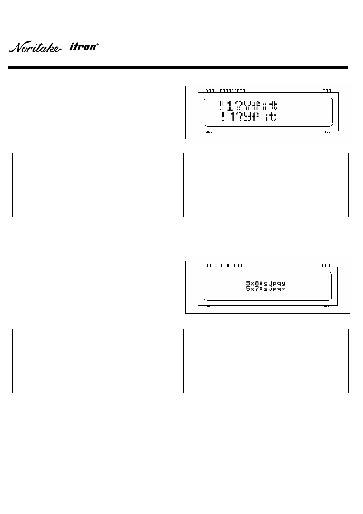
4.7 Alternative Magnifed Font
4.8 Alternative 5×7 Font
Only under 2×2 Font Magnification mode, 28 characters
such as ‘!’, ‘1’, ‘(‘, etc. can also be displa
y
ed in Alternative
Magnified font instead of Common font. Refer to
y
our
specific module specification “Select/Deselect Alternative
Magnified Font” and Font Specification DS−1519−0002
“Alternative Magnified Font”.
Fig. 4-11
These five characters ‘
g
’, ‘
j
’, ‘p’, ‘q’ and ‘
y
’ can also be
displayed in Alternative 5×7 Matrix font instead of
Common Refer to your specifc moule specification
“Select/Deselect 5×8 Matrix Font” and Font Specification
DS−1519−0002 “Alternative 5×7 Matrix Font”.
Fig. 4-12
void alternative_magnified_font( )
{
const int command_set [36] = {
0x1F, 0x28, 0x67, 0x40, 0x02, 0x02, //Character Size
0x21, 0x31, 0x3F, 0x59, 0x66, 0x69, 0x74,
//Character Code
0x1F, 0x24, 0x00, 0x00, 0x02, 0x00, //Cursor Position
0x1F, 0x28, 0x67, 0x06, 0x01, //Alternative Font
0x21, 0x31, 0x3F, 0x59, 0x66, 0x69, 0x74,
void alternative_5x7_font( )
{
const int command_set [40] = {
0x1F, 0x24, 0x07, 0x00, 0x01, 0x00, //Cursor Position
0x35, 0x78, 0x38, 0x3A, 0x67, 0x6A, 0x70, 0x71, 0x79,
//Character Code
0x1F, 0x24, 0x07, 0x00, 0x02, 0x00, //Cursor Position
0x1F, 0x28, 0x67, 0x04, 0x80, //Alternative Font
0x35, 0x78, 0x37, 0x3A, 0x67, 0x6A, 0x70, 0x71, 0x79,
Example 4-9
Example 4-10
//Character Code
0x1F, 0x28, 0x67, 0x06, 0x00}; //Common Font
for(n = 0; n < 36; n++)
{
data = command_set [n];
parallel_out (data);
}
}
//Character Code
0x1F, 0x28, 0x67, 0x04, 0x81}; //Common Font
for(n = 0; n < 40; n++)
{
data = command_set [n];
parallel_out (data);
}
}

DOCUMENT NUMBER :E-M-0001-00
C++ Sample Code Y-Series
15/18 E2−5008−00
4.9 Displaying Symbols (Character Code Type)
4.10 Displaynig Symbols (International Font Set)
One of the 10 charcter code types is selectable, and its
symbols and characters are added to Common font set.
Refer to your specific module specification “Specif
y
character code type” and Font Specification
DS−1519−0002 “Character Code Type”.
Fig. 4-13
One of the 14 international font sets is selectable, and its
s
y
mbols and characters replaces the coresspondin
g
code
characters in Common font set. Refer to
y
our specific
module specification “Specif
y
International font set” and
Font Specification DS−1519−0002 “International Font Set”.
Fig. 4-14
void character_code_type( )
{
const int command_set [77] = {
0x1F, 0x24, 0x06, 0x00, 0x00, 0x00, //Cursor Position
0x1B, 0x74, 0x01, //Character Type Code
0x80, 0x81, 0x82, 0x83, 0x84, 0x85, 0x94, 0x8F, 0x8E,
0x8D, 0x8C, //Character Code
0x1F, 0x24, 0x08, 0x00, 0x01, 0x00, //Cursor Position
0x97, 0x98, 0x99, 0x9A, 0xE8, 0xE9, 0xEA, 0xEB,
//Character Code
0x1F, 0x24, 0x06, 0x00, 0x02, 0x00, //Cursor Position
0x1B, 0x74, 0x03, //Character Code Type
Example 4-11
void international_font_set( )
{
const int command_set [31] = {
0x1F, 0x24, 0x08, 0x00, 0x01, 0x00, //Cursor Position
0x40, 0x5B, 0x5C, 0x5D, 0x7B, 0x7C, 0x7D, 0x7E,
//Character Code
0x1F, 0x24, 0x08, 0x00, 0x02, 0x00, //Cursor Position
0x1B, 0x52, 0x0B, //International Font Set
Example 4-12
0xE3, 0xE4, 0xE8, 0xE9, 0xEA, 0xF1, 0xF2, 0xF3, 0xFB,
0xFC, 0xFD, //Character Code
0x1F, 0x24, 0x06, 0x00, 0x03, 0x00, //Cursor Position
0x1B, 0x74, 0x01, //Character Code Type
0xB1, 0xB2, 0xB3, 0xB4, 0xB5, //Character Code
0x1B, 0x74, 0x04, //Character Code Type
0x90, 0x91, 0x92, 0xE0, 0xE1, 0xE2}; //Character Code
for(n = 0; n < 77; n++)
{
data = command_set [n];
parallel_out (data);
}
}
0x40, 0x5B, 0x5C, 0x5D, 0x7B, 0x7C, 0x7D, 0x7E};
//Character Code
for(n = 0; n < 31; n++)
{
data = command_set [n];
parallel_out (data);
}
}
DOCUMENT NUMBER :E-M-0001-00
C++ Sample Code Y-Series
16/18 E2−5008−00
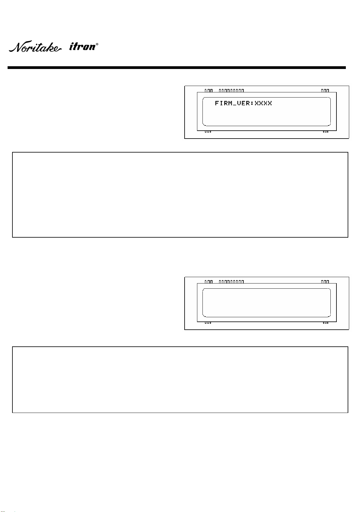
4.11 Displayning Firmware Version
4.12 Power Save Mode
A version number of installed firmware can be displa
y
ed
by the following command set.
Fig. 4-15
Fig. 4-16
Even though the module does not display an
y
thin
g
,
standby power still exists. Power Save Mode minimizes
the standby power. The mode is cancelled when the next
command is received.
void displaying_firmware_version( )
{
const int command_set [17] = {
0x1F, 0x28, 0x65, 0x01, 0x49, 0x4E, //User Setup Mode
0x1F, 0x28, 0x65, 0x14, //Display Firmware Version
0x1F, 0x28, 0x65, 0x02, 0x4F, 0x55, 0x54}; //Direct Command Mode
for(n = 0; n < 17; n++)
{
data = command_set [n];
parallel_out (data);
}
}
Example 4-13
void power_save_mode( )
{
const int command_set [5] = {0x1F, 0x28, 0x61, 0x40, 0x00};
for(n = 0; n < 5; n++)
{
data = command_set [n];
parallel_out (data);
}
}
Example 4-14

DOCUMENT NUMBER :E-M-0001-00
C++ Sample Code Y-Series
17/18 E2−5008−00
5 Optical Color Filters
Product images, including color, may differ from actual product appearance.
Fig.5-1 (No Filter)
Fig. 5-2 (With Green Filter)
Fig. 5-3 (With Blue Filter)
The original color of illumination is blue-green (Fig. 5-1), and it has a wide range of the color spectrum. Therefore, the
color can be changed with optional color filters easily (Fig. 5-2 and 5-3). Noritake provides optional color filters. For
further information, please contact your local sales representative or visit our websit at www.noritake-
elec.com/colors.htm.

DOCUMENT NUMBER :E-M-0001-00
C++ Sample Code Y-Series
18/18 E2−5008−00
6 Revision History
Version Date Revision Description Prepared Approved
00 01/29/09 Initial Issued M. S. A. N.
This manual suits for next models
1
Table of contents


