Noritz EZ2FVK-2 User manual

1
Installation Manual
Potential dangers from accidents during installation and use are divided into the following three
categories. Closely observe these warnings, they are critical to your safety.
DANGER indicates an imminently hazardous situation which,
if not avoided, will result in death or serious injury.
WARNING indicates a potentially hazardous situation which,
if not avoided, could result in death or serious injury.
CAUTION indicates a potentially hazardous situation which,
if not avoided, may result in minor or moderate injury.
Installation must conform with local codes, or in the absence of local codes, the National Fuel Gas Code, ANSI
Z223.1 /NFPA54-latest edition.
The manufacturer reserves the right to discontinue, or change at any time, the designs and/or specifications of its
products without notice.
DANGER:
• Never use this Vent Kit other than for the Applicable Model (including the model manufactured by others)
designated in this manual.
WARNING:
• If the information in this manual is not followed exactly, a fire or explosion may result causing property
damage, personal injury or death.
• Do not install only with the Start-up Guide. Read this manual also before installation.
Requests to Installers
• This manual is for the vent components for the designated tankless water heater. For the installation
of the Tankless Water Heater itself, read the installation manual packed with it.
• In order to install this vent kit correctly, read this installation manual carefully, and follow the installation
instructions.
• Failures and damage caused by erroneous work or work not as instructed in this manual are not
covered by the warranty.
• Check that the installation was done properly in accordance with this installation manual upon
completion.
• After completing installation, place this installation manual in a plastic pouch and attach it to the side
of the water heater, or hand it to the customer to retain for future reference.
Vent Kit for Condensing Tankless Gas Water Heater
Model: EZ2FVK-2 (Flex Vent 2" Kit 35 feet)
EZ2FVK-2-LT
Rev. 07/20
DANGER
WARNING
CAUTION
CAUTION
Prohibited Be sure to do

2
1.General Information
Property damage, personal injury or death can result if these instructions are not followed. They are a guide for
professional installers generally familiar with the installation and maintenance of heating equipment and related
vent systems.
• Flex Vent 2" Kit is designed only for the installation inside of B-Vent as sleeve.
Do not use it for other installation method. Also do not use it outdoor.
• Do not use for anything other than designated Tankless Water Heater (including the model manufactured by
others).
• Flex Vent 2" Kit can be installed at zero clearance to combustible materials.
• Appliances can be started up immediately after Flex Vent 2" Kit is installed and inspected.
• Flex Vent 2" Kit systems expand and contract slightly during heating cycles and
must be installed following included instructions.
• Keep Flex vent greater than 40°F (5°C) during installation. Damage will occur if handled or
installed at lower temperatures.
• Information regarding certification of "Flexible vent pipe and connections".
Standard(s) UL-1738 Standard for Venting Systems
ULC-S636-08 Standards for type BH Gas Venting Systems
Product PP Flexible 2", PP Single Wall Pipe 2"
Brand name InnoFlue Flex - Centrotherm
Models IFVL, IFSF, IANS, ISEL, IACE
40°F
(5°C)

3
2.Included Accessories
Part Shape Q'ty
Bag
"Step-1"
Flex Feeder 1
Base Junction Support
• Clamp x3 1
Base Junction
Adapter Set 1
Bag
"Step-2"
Top Flex support 1
Universal Rain Cap 1
Bag
"Step-3"
Rigid 45 Elbow Set
• Coupler Fitting
• Connector Ring
• 45 degree PP elbow
1
Coupler O-Ring
Coupler Retainer 1
O-ring lubricant 1
Fastening Screws 2
Aluminum tape 1
Part Shape Q'ty
Installation Manual
(This document) 1
EZTR 35 Feet
Start Up Guide 1
Flex Pipe 2"
approximately 35 feet
1
Flex Sleeve 1
The following accessories are included.
Check for any missing items before starting installation.

4
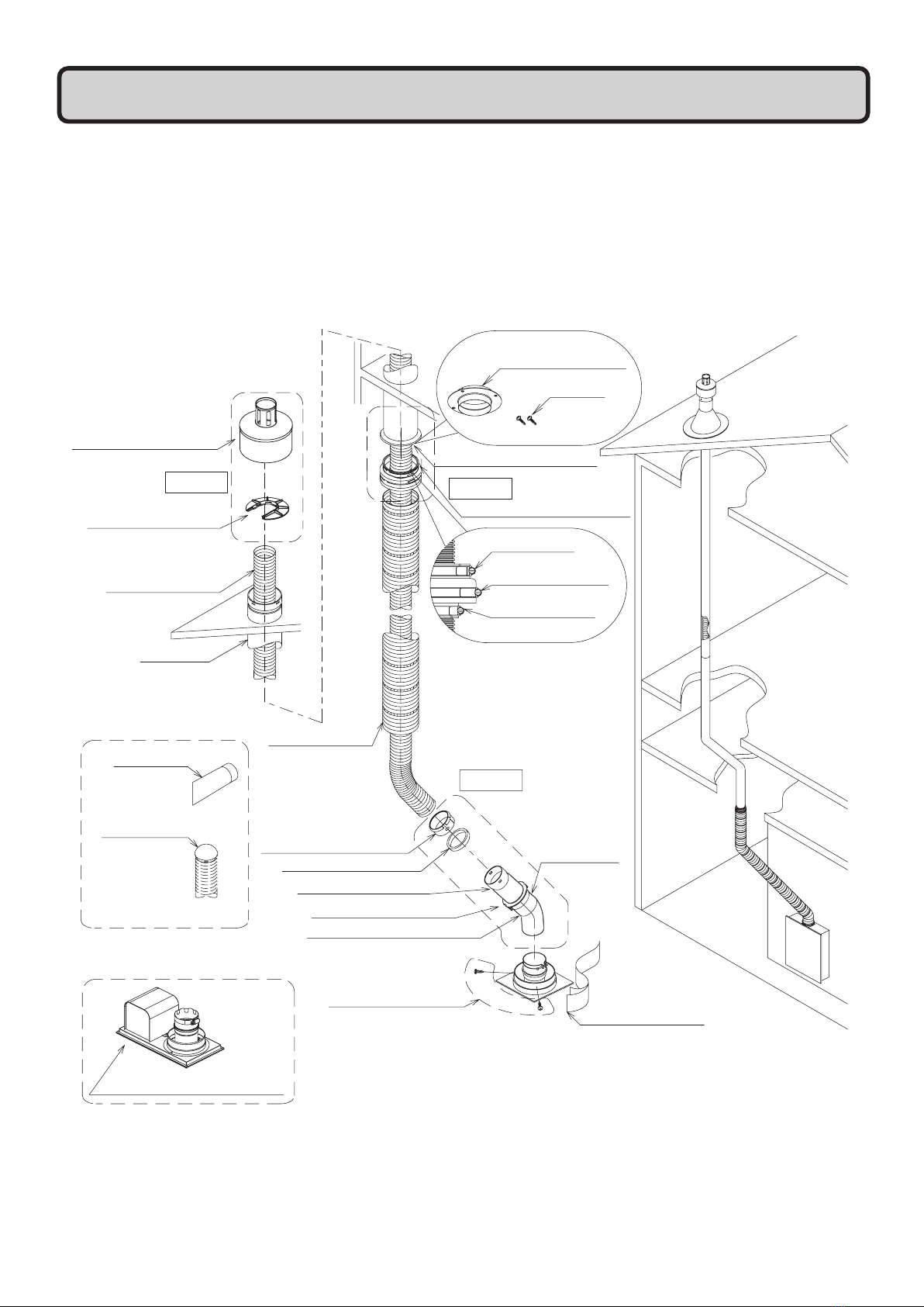
• Flex Vent 2" Kit is designed only for installation inside of B-Vent wall. Do not use it for other installation method.
Also do not use it outdoor.
• Only approved for use with the designated B-Vent manufactures.
• If the Rain Cap and B-Vent itself are damaged by corrosion, it must be replaced with new ones.
• Before installation, make sure no nails or screws have penetrated the inner B-Vent wall where the flexible vent will be
installed. Those obstructions may damage the flexible vent and may result in fires, property damage or exposure to Carbon
Monoxide.
• Do not reuse the flexible vent once it has been installed, removal of the vent may have caused damage to the flexible
vent.
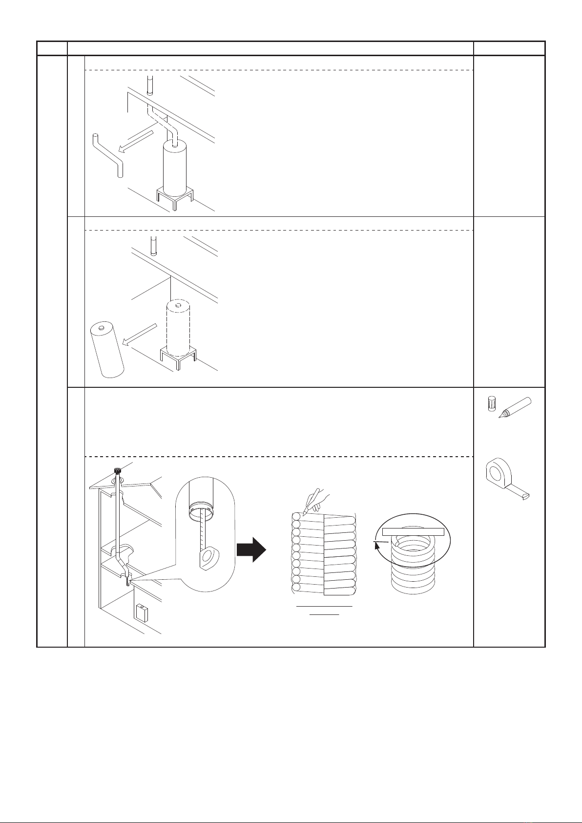
• Keep Flex vent at a temperature greater than 40°F (5°C).
Material temperature is not less than 40°F (5°C) during installation.
Damage will occur if handled or installed at lower temperatures.
• If the temperature if below 40°F (5°C) it's recommended that you store the
Flex Vent
in a warm room or car for 30 minutes.
If you find that the Flex Vent is still stiff, you may need to use a hair dryer and warm both ends of the vent to prevent breakage.
• Make sure components are kept under these following conditions.
* Clean and dry place.
* Above 40°F (5°C)
* Keep out of direct sunlight.
• Minimum bend radius should be more than 7 inch.
• Handle the flexible vent carefully.
Dropping, Crushing and Stacking may cause damage, and may result in fires, property damage or exposure to Carbon
Monoxide.
• Flex Vent 2" Kit cannot be painted.
• Avoid places where open flame are common, such as those where gasoline, benzene and adhesives are handled, or places in
which corrosive gases (ammonia, chlorine, sulfur, ethylene compounds, acids) are present.
• Avoid installation in places where dust or debris will accumulate.
Dust may block the air-supply opening, causing the performance of the device fan to drop and incomplete combustion may
occur as a result.
• Avoid installation in places where special chemical agents (e.g., hair spray or spray detergent) are used.
• For your safety, do not attempt to work on a rooftop until safety precautions have been identified and proper fall safety
measures have been taken, including the use of ladders or stairways, and personal protective equipment (PPE).
• Installation in windy or wet conditions require additional precautions. Follow local safety regulations.
40°F
(5°C)
r>7 inch
3.General Safety
• If similar flexible vent has already been installed, it must be replaced with this designated new Flex Vent Kit.
DANGER
WARNING
Checkup

5
4.Before Installation (Check the condition of installation site)
• Check for any damage to components that may have occurred during transportation before installation.
• Consult with the customer regarding the location of installation.
•
Do not install this Flex Vent 2" Kit in a place where it may be subject to falling objects, such as under shelves.
•
Flex Vent 2" Kit
vent systems expand and contract slightly during heating cycles and must be installed
according to supplied instructions.
Check that the following items are "(OK) Can be installed" before installation.
If all items are "(OK) Can be installed", proceed to the next step, "6. Installation".
Check point Can be installed(OK) Cannot be installed(NG) Mark "
" if each
condition is matched.
1. Vent system.
Vent system is used by 1 appliance only
Common vent
2. No Screws or
nails protruding
within the B-Vent
No
Yes
(If Yes to protruding screws or nails,
flex vent cannot be installed.)
CAUTION
PAUSE FOR A MOMENT
Verify if the installation of a rain cap of different appearance will conflict with Home
Owners Associations rules to prevent future issues.
If NOT, contact customer care to purchase optional installation kit for existing Rain Cap.
Contact details are available on the rating plate of the water heater.

6
Check point Can be installed(OK) Cannot be installed(NG) Mark "
" if each
condition is matched.
3.B-Vent shape
Round
Oval
4.B-Vent diameter 3" or 4" 5" or larger
5.Horizontal distance
between B-Vent
connection from the
ceiling and the unit is
no more than 5ft.
5ft or less More than 5 ft
6.Vent length from the
top of unit to the rain
cap.
35 feet or less More than 35 feet

7
Check point Can be installed(OK) Cannot be installed(NG) Mark "
" if each
condition is matched.
7.Ambient
temperature where
unit is installed.
More than 40°F (5°C) 40°F (5°C) or less
*Refer to page 4
8. Accessibility to
Rain Cap
Can access Rain Cap Cannot access Rain Cap(High
pitch etc.)
40°F
(5°C)

5.Sample of the Venting system
■ The pictured image of the system consisted of this Vent Kit and the explanation of the name of the
components
The image of the Flex Vent 2" Kit system is as listed below.
Only when the venting components and the water heater are installed correctly, the customer can use the
hot water correctly and safely.
The numbers before the names of the components are corresponding to the same component names as in
step "6. Installation".
8
䐧Coupler Retainer
䐦A Coupler Fitting
䐦B Connector Ring
䐦C 45 degree PP elbow
䐥Flex Sleeve
䐤Base Junction Support
䐡Flex Pipe 2"
Step-2 Step-1
Step-3
䐤A B-Vent
Clamp
䐤B Flex Sleeve
Clamp
䐤C Flex Pipe
Clamp
䐦
Rigid 45
Elbow Set
䐭
䐬
Flex Feeder
Installation tool
䐩Fastening Screws
Aluminum tape
䐟Universal Rain Cap
䐢B-Vent
䐨Coupler O-Ring
䐫
O-ring
lubricant
䐣A Base Junction Adapter
䐣B Screws
䐣
Base Junction Adapter Set
Conversion Kit
Flex Vent 2" Conversion Kit
䐪
䐠Top Flex Support

9
6.Installation
In the installation, some work will be done above the roof, extra care and fall protection may be
required. Take extra care and responsibility to do the installation as safely as possible.
2.Tools necessary for the installation
3.Installation Procedure
Follow the below motioned procedure and install correctly. Specially, be sure to check each [Point] carefully.
If not installed correctly, the water heater will not function properly.
WARNING:
• For your safety, do not attempt to work on a rooftop until safety precautions have been identified and
taken including without limitation fall protection measures, ladders or stairways, and personal protective
equipment(PPE).
•
Installation in windy or wet conditions require additional precautions. Follow local safety regulations.
[Maximum Vent lengths]
• Max. Straight Vent Length: 35'(10.5m).
• Max. allowable 45 degree elbows(B-Vent) are 2 elbows.
* Not including "⑧C 45 degree PP elbow"
* No 90° elbows(B-Vent)
• Only when the all conditions of "4. Before Installation (Check the condition of installation)" are
satisfied, proceed with the installation, following the below mentioned installation procedure.
①
Screwdriver
②
Cutting tool
③
Tape Measure
④
Marker
• Phillips head
• Flat head
• Box wrench(5/16")
• For cutting the flexible vent.
• PVC Cutter
• Box Cutter etc.
* Hand saws are not approved
for cutting.
Follow the instruction in the Flex Vent 2" Conversion Kit
Installation Manual to install the Flex Vent 2" Conversion Kit.
Note : This manual illustrates installation for the NRC663-FSV.
Installation for other models may vary slightly.
• Only use the parts provided in the package for construction.
Using parts other than the ones provided may cause the product to be assembled incorrectly.
Be sure to do
Flex Vent 2"
Conversion Kit*
e.g.) Water Heater: EZTR50 (EZ98DV)
Be sure to do
Be sure to do
or

10
Step
Installation Procedure(ex. @Garage)
Necessary Tool
1
Remove the B-Vent between bottom of ceiling and tank type water heater.
2Drain and remove the tank type water heater.
3
Use a measuring tape to measure from the bottom of the "④B-Vent" to the roof
termination to get the total length of the vent run. Transfer that measurement to the
"③Flex Pipe 2"" by making a mark from inner side to help you know when you have
reached the roof termination.
* The Measured vent run length will be used in procedure No. 23 later. Make a note of
the Vent Run Length.
Marker
Tape Measure
Step-1
(Work where equipment is installed)
Approx.4 feet/round
4ft
8ft
12ft
16ft
20ft
:
:
Side view of ex
vent coil

11
Step
Installation Procedure(ex. @Garage)
Necessary Tool
4Grab Bag Labeled "Step-1" for this step of the installation.
Measure "④B-Vent" Diameter
* Installation for 3" or 4" where "④B-Vent" does not come down through the ceiling.
Remove the four screws from "⑤A Base Junction Adapter"
Place and center "⑤A Base Junction Adapter" (Lower side) over the opening of
ceiling.
Attach "
⑤
A Base Junction Adapter" with four screws (must be field supplied) to the ceiling.
* Installation for 4" "④B-Vent"
Insert "⑤A. Base Junction Adapter" onto the 4" "④B-Vent"
Attach "⑤A. Base Junction Adapter" with two "⑤B Screws" from outer pipe of
"④B-Vent".
5
Insert "⑥Base Junction Support" to the bottom of "④B-Vent" that is sticking out
from the ceiling or "⑤A. Base Junction Adapter". Firmly tighten "⑥Base Junction
Support" with "⑥A. B-Vent Clamp", be careful not to over tighten, this may distort the
rubber. Check to see if it secure by pulling by hand.
* The tightening torque should be between 7 and 10 in lb.
* Do not apply "⑭O-ring lubricant" to "⑥Base Junction Support"
⑥
Base Junction
Support
If strength of the ceiling is not sufficient (i.e. plasterboard), take appropriate
measures to ensure safe installation.
Be sure to do
⑤A Base Junction
Adapter
⑤B Screws
Phillips Head
Screwdriver
Installation for 4" B-Vent
Installation for 3" B-Vent Installation for no B-Vent
Protruding
NO USE
NO USE Use appropriate screws
for the ceiling.
(must be field supplied.)
Mpxfs!Tjef
Flat head
Screwdriver
Box wrench
(5/16")
or

12
Step
Installation Procedure(ex. @Garage)
Necessary Tool
6Push the "⑮Flex Feeder" into the tip of the "③Flex Pipe 2"".
③
Flex Pipe 2"
⑮Flex Feeder
7
Insert the "
③
Flex Pipe 2"" into the "⑥Base Junction Support" until you touch the
inside of the rain cap on the roof.
With the "
③
Flex Pipe 2"" fully inserted into the vent, make a mark at the "⑥Base
Junction Support" so you can check for movement during the rest of installation.
Marker
Step-1
(Work where equipment is installed)
Install the "⑮Flex Feeder" always, even in the case of straight B-Vent runs.
("⑮Flex Feeder" prevents debris from falling into the "③Flex Pipe 2"".)
Be sure to do
When pushing "③Flex Pipe 2"" through the B-Vent, if there is unusual feeling
(touching the bump of screw, etc.), do not continue to push in and stop the installation.
Be sure to do
Do not use the "③Flex Pipe 2"" at any jobsite with vent runs longer than 35', do
not join two shorter flex pipes together even if the run is less than 35'.
Prohibited
[Point]
Before inserting, try to straighten curl of the tip of "③Flex Pipe 2"" as much as possible.
However, when doing so, bending radius should be more than 7 inch.
[Point]
Continue to push "③Flex Pipe 2"" strongly until the end and make sure that it does not
stop in the middle.
r>7 inch

13
Step
Installation Procedure(ex. @Garage)
Necessary Tool
8Take extra care to ensure that the "③Flex Pipe 2"" does not slip by checking the mark you made
on the "③Flex Pipe 2"". Firmly tighten "③Flex Pipe 2"" with "⑥C. Flex Pipe Clamp", but be
careful not to over tighten as it may distort the "③Flex Pipe 2"". Check to see if it is firmly secured
by pulling it by hand.
* The tightening torque should be between
7 and 10 in lb.
*
The assembly image figure for all parts in below Step 2 (Procedure 9–14)
Use this Image to check for correct assembly of the components.
9
Grab Bag Labeled "Step-2" and necessary tools for this step of the installation.
Climb up on the roof and access the Rain Cap.
Ladder
Wet Towel
Marker
Bag"Step-2"
Step-1
(Work where equipment is installed)
Step-2
(Work on rooftop)
[Point]
When climbing up on the roof, use appropriate fall protection to guard against falls. Make
sure that safety comes first at your own risk.
Final drawing in this Step2
(a cross section)
Final image in Step 2
Flat head
Screwdriver
Box wrench
(5/16")
or
PVC Cutter
Box Cutter
or
Step-2
䐡Flex Pipe 2”
䐠Top Flex Support
䐟
Universal Rain Cap

14
Step
Installation Procedure(ex. @Garage)
Necessary Tool
10
Take off the existing rain cap and place it on the area where it does not fall from the rooftop.
* Make sure the inside surfaces of the "④B-Vent" are clean to ensure a good seal of
the parts in this step.
Wet Towel
11
Use a marker to mark the original position of the "③Flex Pipe 2"", at "④B-Vent"'s upper tip.
Marker
12
Slide-in the
"
②
Top Flex Support"
to the
"③Flex Pipe 2"".
②
Top Flex
support
Mark is very important for the function. Do not skip this step.
(Necessary for the next step.)
Be sure to do
Inert the
"
②
Top Flex Support"
's slit straight into the Flex Pipe groove.
Be sure to do
Verify that you can see the mark you made at the top end of the "
②
Top
Flex Support" in the previous step.
Be sure to do
Step-2
Slide-in
Pull up
Mark

15
Step
Installation Procedure(ex. @Garage)
Necessary Tool
13 Use a marker to mark the cutting position.
14 Attach "①Universal Rain Cap"
①
Universal
Rain Cap
Step-2
(Work on rooftop)
* All cuts must be made at right angle to the pipe. All field cuts must be deburred.
* T
ake precaution not to drop debris into "③Flex Pipe 2"". In case debris is dropped,
remove from the lower end of the "
③
Flex Pipe 2"".
Mark
3 ribs
Completely Insert "①Universal Rain Cap" into the "③Flex Pipe 2"",
"①Universal Rain Cap" overlap "④B-Vent" by 1/2".
Be sure to do
More
than
1/2”
}
PVC Cutter
Box Cutter
or

16
Step
Installation Procedure(ex. @Garage)
Necessary Tool
15 Grab Bag Labeled "Step-3" and necessary tools for this step of the installation.
Mount the water heater at the appropriate height according to the chart below, connect the gas,
cold and hot water lines, and drain pipes. Follow the equipment's installation manual on how to set
the equipment's clearance from combustibles.
Tape measure
* The location(height) where equipment can be installed varies by horizontal distance
(L) shown below. Follow the below chart and install accordingly.
■Equipmentinstallationupperlimitheightchartbyhorizontaldistance
Horizontal distance (L) 0' ~1' ~2' ~3' ~4' ~5'
More than height(H) 2' 2' 2'
2.6' 3' 3'
[Point]
Before you start the plumbing, imagine where the "③Flex Pipe 2"" will be ran and account
for any clearance needed.
[Point]
Always follow the above chart and determine the equipment's installation location (height).
→Ifitisnotfollowed,therewillbenonconformancesuchaslargetensiontothefinal
connecting area of the vent pipe and/or can't connect.
Step-3
(Work where equipment is installed)
<Ceiling>
<Type (A)> <Type (B)>
L
(Max. 5feet)
H
e.g.) EZTR40 e.g.) EZTR50
B-Vent end
without "⑥Base Junction
Support"

17
Step
Installation Procedure(ex. @Garage)
Necessary Tool
16 Insert "⑧Rigid 45 Elbow Set" to the equipment's vent connector pipe. When inserting "⑧Rigid
45 Elbow Set", there is tension when it passes through the o-ring within the equipment’s vent
connector pipe. Continue to insert "⑧Rigid 45 Elbow Set" until it is firmly seated all the way into
the base of the vent connector pipe.
⑧Rigid 45
Elbow Set
17
Follow the next [Point] and cut the
"③
Flex Pipe 2"
"
into appropriate length.
Marker
[Point]
If it interferes with water and hot water piping, adjust "⑧Rigid 45 Elbow Set"'s angle so
that it does not interfere. If the contact is unavoidable, take measures such as inserting
heat insulator so that it does not have direct contact.
Step-3
(Work where equipment is installed)
At this step, be very careful when cutting the "③Flex Pipe 2"". If it is cut too
short, you must dispose of the vent or use it on another installation where a
shorter length is required. These vent pieces cannot be lengthened.
Be sure to do
Do not disassemble
"⑧Rigid 45 Elbow Set" to use.
Be sure to do
<Type A> 3"
<Type B> 4 3/4"
PVC Cutter
Box Cutter
or

18
Step
Installation Procedure(ex. @Garage)
Necessary Tool
Step-3
(Work where equipment is installed)
[Point]
When performing the final cut, make the first cut of the "③Flex Pipe 2"" longer to
avoid cutting the "③Flex Pipe 2"" too short. It is easy to determine the length by
following the [Point] below and matching the dimension using the below figure.
[Point]
When determining the cut length, take note on the 2 points listed below.
[Point①]
Determine the proper length not giving too much tension to both
"
⑥
Base Junction Support
"
and
"
⑧Rigid 45 Elbow Set".
[Correct installation] [Incorrect installation]
When the vent pipe is too short,
there will be tension to those
parts.
[Point②]
Be careful not make trap configuration of "
③
Flex pipe 2"".
[Correct installation] [Incorrect installation]
In trap installation, moisture is
trapped inside the vent pipe and
the exhaust can't be vented.

19
Step
Installation Procedure(ex. @Garage)
Necessary Tool
18
Pull
"
⑦Flex Sleeve
"
over
"
③Flex Pipe 2"
"
under the ceiling. Then, push into the bottom of
"
⑥Base Junction Support
"
. And check that
"
③Flex Pipe 2"
"
is sticking out from
"
⑦Flex
Sleeve
"
. (If it is not sticking out,cut
"
⑦Flex Sleeve
"
until
"
③Flex Pipe 2"
"
sticks out.)
⑦Flex Sleeve
* Do not extend the "⑦Flex Sleeve" if it needs to be cut, it should be cut while in its
compressed state.
19
Firmly tighten "⑥B. Flex Sleeve Clamp" of "⑥Base Junction Support", but be careful
not to tighten too much as it may distort the "⑦Flex Sleeve" and rubber. Check to see if
it is firmly fixed by pulling it by hand.
* The tightening torque shall be between 7 and 10 in lb.
Step-3
(Work where equipment is installed)
Pay attention not to get injured from the sharp edge of "⑦Flex Sleeve".
WARNING
OK
NG
Flat head
Screwdriver
Box wrench
(5/16")
or
[Point]
"
③
Flex Pipe 2"" not visible.
[Point]
"
③
Flex Pipe 2"" is visible.

20
Step
Installation Procedure(ex. @Garage)
Necessary Tool
20
See below chart and set "⑩Coupler O-Ring" and "⑨Coupler Retainer" onto the tip of
"③Flex Pipe" in the correct direction.
⑨Coupler
Retainer
⑩Coupler
O-Ring
21
Pull out assembled "⑧Rigid 45 Elbow Set", which are tentatively locked to the
equipment's vent connector pipe. Connect by matching pulled out assembly and 3 lock
clasps of
"
⑨Coupler Retainer
"
, which was set during the previous process.
* Prior to connecting, make sure to apply "⑭O-ring lubricant" to "⑩Coupler
O-Ring".
⑧Rigid 45
Elbow Set
⑭O-ring
lubricant
Step-3
(Work where equipment is installed)
When inserting, "
⑩
Coupler O-Ring" is easy to tear due to pinching.
Therefore, take maximum precaution when working.
Be sure to do
[Point]
Correct way of setting "
⑩
Coupler O-Ring" and "
⑨
Coupler Retainer".
[Point]
When matching the lock of "⑧A. Coupler Fitting" and "
⑨
Coupler Retainer", it is easier to match the lock clasp by
turning the "
⑨
Coupler Retainer" by hand.
Vent Connector Pipe
Lock Clasp
(3 Places)
Table of contents
Other Noritz Water Heater Accessories manuals
Popular Water Heater Accessories manuals by other brands

aquanta
aquanta AQ-CA-G100-ESL installation instructions

Sentera Controls
Sentera Controls SC2A4 Mounting and operating instructions

Toyotomi
Toyotomi SH-70UFF instruction manual

Kelvinator
Kelvinator InstaKnight KGCRB1C installation instructions

Lochinvar
Lochinvar ProtoNode FPC-N35 Startup guide

Sentera Controls
Sentera Controls ECH-8-DM Mounting and operating instructions