EnglishDeutsch
 logo
Brands
  1. Home
  2. •
  3. Brands
  4. •
  5. Noritz
  6. •
  7. Water Heater Accessories
  8. •
  9. Noritz PC-9S Quick guide

Noritz PC-9S Quick guide

Other Noritz Water Heater Accessories manuals

Noritz EZ2FVK-2 User manual

Noritz

Noritz EZ2FVK-2 User manual

Noritz CK-82 User manual

Noritz

Noritz CK-82 User manual

Noritz SS-HB-3 User manual

Noritz

Noritz SS-HB-3 User manual

Popular Water Heater Accessories manuals by other brands

ASKOMA Askoheat-FO Fitting instructions

ASKOMA

ASKOMA Askoheat-FO Fitting instructions

KORADO KORAFLEX PM 14 Series Assembly instructions

KORADO

KORADO KORAFLEX PM 14 Series Assembly instructions

A.O. Smith Product Preservers Powered Anode System user guide

A.O. Smith

A.O. Smith Product Preservers Powered Anode System user guide

Reliance ETC-10X Specifications

Reliance

Reliance ETC-10X Specifications

Rheem RTGH-95X installation instructions

Rheem

Rheem RTGH-95X installation instructions

aquanta AQ-CA-G100-ESL installation instructions

aquanta

aquanta AQ-CA-G100-ESL installation instructions

PAW K35 Installation and operation instruction

PAW

PAW K35 Installation and operation instruction

Lochinvar ProtoNode FPC-N34 Startup guide

Lochinvar

Lochinvar ProtoNode FPC-N34 Startup guide

Jandy EHE 220 installation instructions

Jandy

Jandy EHE 220 installation instructions

ASKOMA ASKOHEAT Fitting instructions

ASKOMA

ASKOMA ASKOHEAT Fitting instructions

ASKOMA ASKOHEAT-S Fitting instructions

ASKOMA

ASKOMA ASKOHEAT-S Fitting instructions

Honeywell VE300 installation instructions

Honeywell

Honeywell VE300 installation instructions

Reznor CK11 quick guide

Reznor

Reznor CK11 quick guide

Reznor 43254 Installation

Reznor

Reznor 43254 Installation

Veil Echo installation guide

Veil

Veil Echo installation guide

Truma AquaGo Electric antifreeze kit manual

Truma

Truma AquaGo Electric antifreeze kit manual

Toyotomi SH-70UFF instruction manual

Toyotomi

Toyotomi SH-70UFF instruction manual

Veil Demi installation guide

Veil

Veil Demi installation guide

https://manuals.online logo
https://manuals.online logoBrands
  • About & Mission
  • Contact us
  • Privacy Policy
  • Terms and Conditions

Copyright 2026 Manuals.Online. All Rights Reserved.

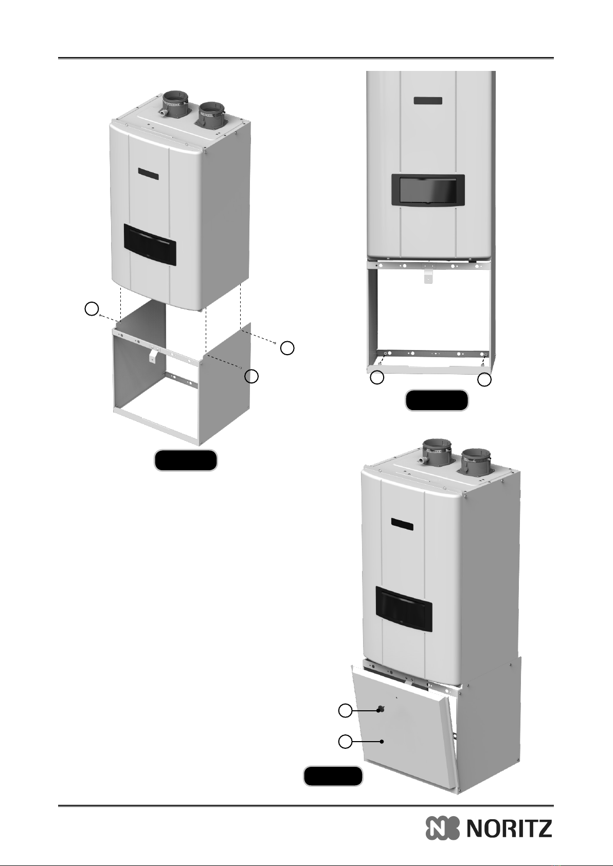
Pipe Cover Installation and Instruction Manual
Do not connect electrical power to the unit until all electrical
wiring has been completed.
1. National Electrical Code
2. National Fuel Gas Code
3. In Canada, CSA C22.1 Canadian Electrical Code
Part 1, and CGA No. B149 (latest version)
4. Local, state, provincial, and national codes, laws,
regulations, and ordinances.
5. In the State of California: The water heater must
be braced, anchored, or strapped to avoid moving
during an earthquake. Contact local utilities for
code requirements in your area or call 866-766-7489
and request instructions.
6. In the Commonwealth of Massachusetts:
a. Outdoor units may be used for summer use only.
b. The water heater may be used for hot
water heating only and may not be used in a
combination of domestic and space heating.
Installation Must Comply With
This water heater must be installed by a qualied and licensed personnel. The installer should be guided by
the instructions furnished with the water heater, and by local codes and utility company requirements.
CAUTION
This manual is intended to be used in conjunction with
other literature provided with the water heater.
This manual includes all related control information.
It is important that this manual, all other documents
included in this system be reviewed in their entirety
before beginning any work.
Installation should be made in accordance with the
regulations of the Authority Having Jurisdiction, local
code authorities, and utility companies which pertain to
this type of water heating equipment.
Important
This installation manual includes information specific to outdoor water
heater installations. This information is meant to replace the venting
section included in the tankless water heater installation manual.
The tankless water heater installation manual includes instructions
that will be necessary for the proper installation of all other functions,
such as water and gas piping, wall mounting, control programming, etc.
Failure to follow these instructions could result in substantial property
damage, severe personal injury, or death. This installation shall be done
by a qualified service agency in accordance with these instructions, all
applicable codes, and requirements of the authority having jurisdiction.
Failure to follow these instructions could result in substantial property
damage, severe personal injury, or death.
WARNING
Note:
The manufacturer reserves the right to make changes or updates without notice and will not be held liable for errors in
literature.
PLEASE KEEP ALL INSTRUCTIONS FOR FUTURE REFERENCE.
Applicable for NRCP111/98 series only.
Kit# PC-9S
Rev.01/19
Part Shape Q’ty
1Front Cover 1
2Left Plate 1
3 Right Plate 1
4 Front Cover Bracket 1
5 Case Bracket 2
Part Shape Q’ty
6 Frame Bracket 1 2
7Frame Bracket 2 1
8Dry Wall Anchor 2
9Screws (M4x10L) 12
10 Knob 1
11 Installation Instruction 1
2
2
3
9
9
9
9
9
6
4
7
Included Pipe Cover Kit
Pipe Cover Kit Components & Dimension
44" [1120mm]
16.5" [420mm]
17.3" [440mm]
14.9" [380mm]
1
10
3
Installing the Pipe Cover
1. Pre-Assemble Frame before installation
2. Install Pipe Cover onto Water Heater
1) Assemble the Front Cover Bracket (
④
) to the
one of the Frame Bracket 1 (
⑥
).
2) Assemble this Frame Bracket 1 (
⑥
) assembled
Front Cover Bracket to the Left and Right Plate
(
②,③
) with Screws (
⑨
).
3) Secure the two Frame Brackets 1, 2 (
⑥,⑦
) to
the Left and Right Plate (
②,③
) with Screws (
⑨
).
1) Remove the mounting 4 screws (A) from the
bottom and sides of the appliance. Refer to
Figure 1.
2) Install the two Case Bottom Brackets (
⑤
) to
the bottom of the appliance with the 4 screws
(A) removed in step 1). Refer to Figure 2.
3) Slide the Pipe Cover assembly onto the
bottom of the appliance. Align the mounting
holes and temporarily mount the Pipe Cover
with the 4 screws (
⑨
). Refer to Figure 3.
4) The 'back' bottom Frame Bracket 1(
⑥
) inserts
into the temporarily mounted Pipe Cover.
Mark the locations to attach the Pipe Cover to
the wall onto the 'back' bottom Frame Bracket
1(
⑥
).
5) Remove the Pipe Cover from the wall and
then drill two holes on the wall as marked.
For drywall, drill two 3/16-in. holes (other wall
material must be required alternate mounting
details).
5
A
A
A
A
5
Figure 1
Figure 2
2
3
9
9
9
9
9
9
6
4
7
6
4
6) Attach 'back' bottom Frame Bracket 1(
⑥
) to
the wall with two dry wall anchors (
⑧
). Refer
to Figure 4.
7) Attach the pre-assembled Pipe Cover of
above 2 onto the bottom of the appliance.
Tighten the 6 screws on the both sides of
Pipe Cover pre-assembled.
8) Attach the Front Cover (
①
) to the Pipe Cover
with the Knob (
⑩
). Refer to Figure 5.
9) With the Pipe Cover ush with the appliance,
tighten the screws on the 'back' bottom Frame
Bracket 1(
⑥
).
Figure 3
Figure 4
Figure 5
9
8
10
1
8
9
9