aquanta AQ-CA-G100-ESL User manual

Smart Water Heater Controller
Installation Instructions
For Natural Gas Water Heaters
Model: AQ-CA-G100-ESL
Version 2.2g
©2018 Aquanta Inc.

2
Introduction
Congratulations on the purchase of your Aquanta
Smart Water Heater Controller!
The Aquanta water heater controller works with your
new or existing natural gaswater heater to bring it out
of the basement and into the palm of your hand. It
heats water only when you need it, offering cost
savings and intelligent controls.
This manual describes the physical installation of the
Aquanta Controller and associated sensors. It can
easily be installed by most homeowners.
First, install the Aquanta Controller on the top of the water heater and connect the
sensors. Then, apply power to the Aquanta Controller, connect it to your home Wi-
Fi network, register with the Aquanta Portal and you have a smart water heater!
The Aquanta Controller contains a Wi-Fi transmitter module FCC ID: VPYLBYD. This
device complies with Part 15 of FCC Rules and Industry Canada license-exempt RSS
standard(s). Operation is subject to the following two conditions: (1) this device may not
cause interference, and (2) this device must accept any interference, including
interference that may cause undesired operation of this device.
FCC CAUTION
Changes or modifications not expressly approved by Aquanta Inc. could void the user’s
authority to operate the equipment. This transmitter must not be co-located or operated
in conjunction with any other antenna or transmitter.

3
Tools Needed:
•Phillips screw driver
•Electric drill with 1/8th inch drill bit
•Smart phone, tablet or laptop with Wi-Fi
Parts Included:
1. Aquanta Controller
2. Temperature Sensors (2)
3. Leak Sensor (Optional)
4. Cable Ties for Temperature
Sensors (4)
5. Cable Management Clips (4)
6. Mounting Bracket

4
Aquanta Controller Installation
The Aquanta Controller is the brain of the system, containing the electronics,
sensor connections and Wi-Fi communications module.
1. If your water heater is atmospheric-vented
natural gas, verify that your gas valve is an
electronic style, as shown in the picture on the
right. Aquanta cannot interface with the older
mechanical style valves.
2. If your atmospheric-vented water heater has the
correct gas valve, note the current setting of the
gas valve knob, then turn it to PILOT.
3. If your water heater is power-vented natural gas, unplug it from the electrical power
outlet before proceeding with the installation.
4. Find a spot for the Aquanta Controller on top of your tank that is within 3 feet of
the temperature and pressure relief valve (T&P Valve).

5
5. Holding the supplied mounting bracket in place, mark the
location of the screw holes and drill two 1/8th inch pilot
holes. Use the two supplied ½ inch long silver sheet metal
screws to secure the mounting bracket in place.
7. Place the Aquanta Controller on the bracket by sliding the
two plastic tabs on the controller through the two slotted
holes on the mounting bracket and pressing down. Then
secure the Aquanta Controller to the mounting bracket
using one black Phillips head screw (supplied).
8. For atmospheric-vented water heaters, connect the
supplied communications cable to the top connector port
on the right side of the Aquanta Controller. Then connect
the other end of the communications cable to the “COM”
port on the water heater gas valve. Then turn the gas
control knob from PILOT to the original setting that you
previously noted.
9. For power-vented water heaters, plug the power cord for the water heater into the
AC power receptacle on the left side of the Aquanta Controller.

6
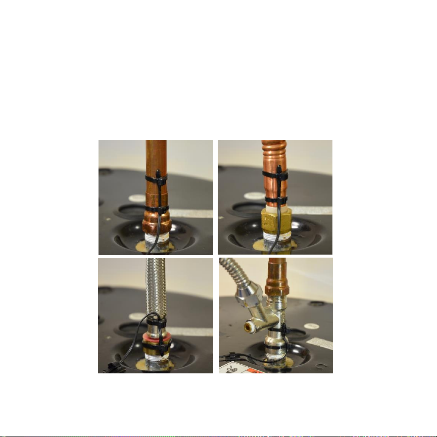
Attaching the Sensors
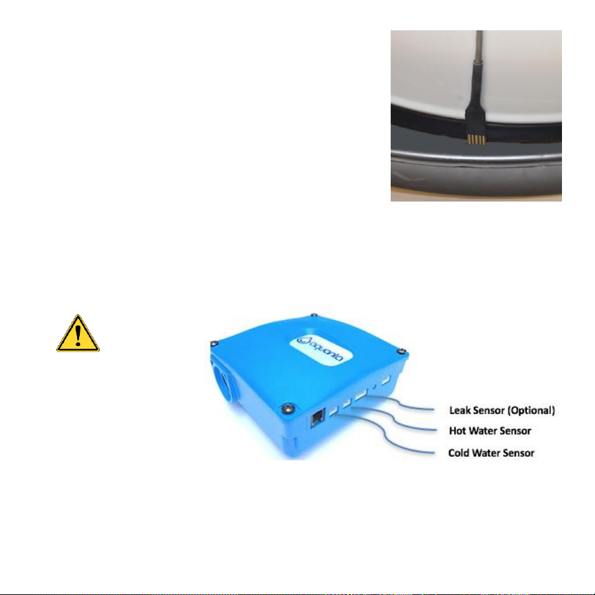
1. Attach one of the supplied Temperature Sensors
to the Temperature & Pressure Relief Valve
(T&P Valve) on the water heater using one of the
supplied Cable Ties. Wrap the Cable Tie around
the T&P Valve and then slide the narrow end of
the tie through the slot. Position the tip of
Temperature Sensor as close as possible to
the water heater and under the Cable Tie, then
pull the Cable Tie as tight as possible over the
bead of the Temperature Sensor.
Ensure that the TemperatureSensor is incontact
with the metal body of the T&P Valve and not
interfering with the operation of the T&P Valve.
Clip off the excess length of the Cable Tie. If
there is another plumbing fitting between the
T&P Valve and the water heater, fasten the
Temperature Sensor to that fitting. Plug this
sensor into the “Hot Water Sensor” connector on
the side of the Aquanta Controller (see Item 4 on
page 8).

7
2. Attach the second Temperature Sensor to the cold-water inlet pipe using two of the
supplied Cable Ties. Wrap one of the Cable Ties around the cold-water pipe and slide
the narrow end through the slot. Position the Temperature Sensor on the cold-water
pipe as close as possible to the water heater and under the Cable Tie, then pull the
Cable Tie as tight as possible. Place a second Cable Tie around the Temperature
Sensorwireto act as a strain relief. Clipoff the excess length of CableTies. Attachment
to four different types of water inlet pipes are illustrated below. Plug this Temperature
Sensor into the “Cold Water Sensor” connector on the side of the Aquanta Controller
(see Item 4 on page 8).

8
3. If you purchased the Optional Leak Sensor, peel
the paper-backing off of the double-sided tape on
the Leak Sensor. Place the leak sensor on the
side of the water heater near the bottom,
preferablydirectlybelow the T&P Valve, such that
the contacts extend into the drip pan beneath the
water heater. Plug this into the “Leak Sensor”
connector on the side of the Aquanta Controller
(see Item 4 below).
4. Connect the sensors to the Aquanta Controller as shown below.
CAUTION:
For proper
operation it is
essential that the Hot and
Cold Water Sensors are
connected to the correct
ports on the Aquanta
Controller. Please ensure
proper installation.

9
5. Four Cable Management Clips are included with the Aquanta unit. Use these
clips to organize the routing of the wires on the water heater. Placing two of
the clips on the back of the Aquanta Controller is a convenient way of retaining
the excess sensor wire.
6. Plug the Aquanta power cord into a nearby electrical power outlet. The LED
should illuminate on the Aquanta Controller; it will blink indicating that a
network connection still needs to be established.

10
Wi-Fi Setup
The Aquanta Controller has built-in Wi-Fi capability for communications with you
home Wi-Fi network. Follow the steps below to establish a connection between the
Aquanta Controller and your home network:
1. Verify that the Aquanta Controller is powered
ON and ready to connect, as shown by a
blinking green light.
2. On a smart phone or other connected device,
find your Wi-Fi networks icon (as if you were at
a coffee shop logging onto a new network), and
select the network called “Aquanta xxxxxxxx”.
3. On many devices (including iOS devices), a
web page automatically appears with the
available Wi-Fi networks. If the web page to the
right does NOT appear, open an internet
browser, type 192.168.0.1 in the web address
bar, and you will see this web page. Click
“Connect” by selecting your home Wi-Fi
network.

11
4. When prompted, enter the password for your home Wi-Fi network. Aquanta
will save this password and use it to connect your Wi-Fi network. Once
connected, the LED on the front of the Aquanta Controller should turn solid
green, indicating that it is connected and in monitoring mode. The Green LED
means that the water heater is activated/powered.
Note: your phone or laptop should return to your home Wi-Fi network once the
Aquanta Controller reboots. If for some reason it does not, disconnect from
the Aquanta Wi-Fi network or reboot your computer.
5. You have now completed the Aquanta installation!
6. Next go to the Aquanta portal to register a user account and connect to the
Aquanta unit at: https://portal.aquanta.io/signUp
7. To login to your account, go to: https://portal.aquanta.io/login
LED and Audible Indications
LED Color
Indication
Green
Normal operation with AC power applied to the hot water
cylinder.
Red
AC power is not being applied to the hot water cylinder.
Aqua, Blue,
Purple
Intelligent Mode Operation: Aqua –AC Power OFF
Blue or Purple - AC Power ON
LED Blinking
Wi-Fi or Internet connection to the server is not available.
Beeping
Leak Sensor has detected a water leak.

12
Tips
1. If your home Wi-Fi network has changed, such as a new router, SSID or
Password, the Wi-Fi Setup procedure for the Aquanta Controller must be
redone. First, the Aquanta Controller must be put into the Wi-Fi
reconfiguration mode (aka AP-mode) by pressing and holding the button
on the right side of the controller for 10 seconds until the LED begins to
blink.
2. You can force the Aquanta Controller to activate your hot water cylinder
permanently by first putting it in Wi-Fi reconfiguration mode, as described
above, and then cycling power to the Aquanta Controller OFF and back
ON.
Thank you and enjoy your Aquanta unit!
Table of contents