Lochinvar Thermal-Stor 100 Series User manual

Thermal-Stor™ HEAT PUMP
STORAGE TANK
INSTALLATION and OPERATION
MANUAL
Series: 100
The information contained in
this manual is intended for use by
qualified professional installers, or
service technicians. Consult your
local expert for proper installation
or service procedures.
Save this manual for future reference.
100339374_2000596325_Rev B
LOW LEAD CONTENT
ᘐWARNING

2
Hazard definitions
The following defined terms are used throughout this manual to bring attention to the presence of hazards of various risk levels
or to important information concerning the life of the product.
ᘐCAUTION
CAUTION
NOTICE
DANGER indicates an imminently hazardous situation which, if not avoided, will result in death or serious
injury.
WARNING indicates a potentially hazardous situation which, if not avoided, could result in death or serious
injury.
CAUTION indicates a potentially hazardous situation which, if not avoided, may result in minor or moderate
injury.
CAUTION used without the safety alert symbol indicates a potentially hazardous situation which, if not
avoided, may result in property damage.
NOTICE indicates special instructions on installation, operation, or maintenance that are important but not
related to personal injury or property damage.
Contents
CONTENTS....................................................................... 2
HAZARD DEFINITIONS................................................... 2
1. GENERAL INFORMATION ........................................ 3
Tank construction ...................................................... 3-4
2. INSTALLATION ........................................................... 5
Transporting and unpacking the unit ............................ 5
Examining the unit ....................................................... 5
Anchoring the unit......................................................... 5
Recommended service clearances ............................. 5
Connecting the hot water source............................... 5-6
Cold water supply .......................................................... 6
Hot water outlet ............................................................ 6
Mixing valve .................................................................. 6
Aquastat / bulbwell ........................................................ 7
Piping the relief valve ................................................... 7
Drain ............................................................................. 7
Completing the installation ........................................... 7
3. OPERATION................................................................ 8
Startup procedure .......................................................... 8
Shutdown procedure...................................................... 8
4. INSPECTION............................................................... 9
5. MAINTENANCE......................................................... 10
Flushing the tank ........................................................ 10
Cleaning the tank................................................... 10-11
Magnesium anode rod inspection............................... 12
Water piping and valve replacement ..................... 12-13
Notes.......................................................................13-15
Revision Notes .................................................. Back Cover
Hot Water Can Scald!
• Water heated to temperatures for clothes washing, dish washing, and other sanitizing needs can
scald and cause permanent injury.
• Children, elderly, and infirm or physically handicapped persons are more likely to be
permanently injured by hot water. Never leave them unattended in a bathtub or shower.
Never allow small children to use a hot water tap or draw their own bath.
• If anyone using hot water in the building fits the above description, or if state laws or
local codes require certain water temperatures at hot water taps, you must take special
precautions:
• Use lowest possible temperature setting.
• Install some type of tempering device, such as an automatic mixing
valve, at hot water tap or water heater. Automatic mixing valve must be selected and
installed according to valve manufacturer’s recommendations and instructions.
• Water passing out of drain valves may be extremely hot. To avoid injury:
• Make sure all connections are tight.
• Direct water flow away from any person.
Protection Must Be Taken Against Excessive Temperature and Pressure!
--Installation of a Temperature & Pressure (T&P) relief valve is required.
ᘐWARNING
ᘐDANGER

Storage Tank Installation and Operation Manual
This manual is intended to cover installation, operation, and
maintenance procedures for Lochinvar’s Heat Pump Storage
Tank.
If questions are not answered by this manual, or if specific
installation, operation, and/or maintenance procedures are not
clearly understood, contact Lochinvar for clarification before
proceeding.
Heat Pump Storage Tanks are designed for indoor use only.
It should be located on a level surface (no more than one-half
degree of slope), capable of supporting the total weight of the
unit when filled to capacity.
The unit should be mounted to the floor following applicable
architectural and local code requirements for the specific
installation site.
The high quality enamel paint, applied to the jacket of the
unit, will provide years of protection against corrosion. If it is
necessary to clean the outside of the unit, a mild cleaning agent
should be used that will not damage the paint.
For all piping connections, the use and/or type of joint
compound or sealer on the joints should be determined
by referring to local codes, accepted standards, and/or the
requirements of the installing contractor.
Tank construction
Heat Pump Storage Tanks are pre-engineered and pre-assembled
complete with all fittings. And like every Lochinvar product,
they are thoroughly tested to ensure proper performance from
the moment they are installed.
Tank Models -- Lochinvar offers four models of the Heat Pump
Storage Tank: HP250G, HP500G, HP750G, and HP1000G.
Tank Orientation -- Lochinvar Heat Pump Storage Tanks are
constructed in a vertical orientation.
Tank Lining -- Lochinvar Heat Pump Storage Tanks are
constructed with glass lining.
ASME -- All Lochinvar storage tanks are constructed per ASME
Section IV requirements, or Section VIII.
Pressure Rating -- Lochinvar tanks are available in 125 psi
working pressure (standard).
Cathodic Protection -- All glass lined tanks are equipped with
magnesium anodes to provide protection against corrosion.
Manway - A 12" x 16" manway is standard on all Heat Pump
Tank models (HP250G, HP500G, HP750G, and HP1000G).
Jacketing -- Lochinvar Heat Pump Storage Tanks are fitted with
a round sheet metal jacket.
• Before using product, read and
understand instructions.
• Save these instructions for future
reference.
• All work must be performed by
qualified personnel trained in the
proper application, installation, and
maintenance of the water systems in
accordance with all applicable codes
and ordinances.
• To prevent serious burns, wear heat
resistant gloves when handling hot
equipment.
Failure to follow this warning could cause
property damage, personal injury, or
death.
1 General information
The following chart (Table 1A) details the relationship of
water temperature and time with regard to scald injury
and may be used as a guide in determining the safest water
temperature for your applications.
APPROXIMATE TIME / TEMPERATURE
RELATIONSHIPS IN SCALDS
120°F More than 5 minutes
125°F 1 1/2 to 2 minutes
130°F About 30 seconds
135°F About 10 seconds
140°F Less than 5 seconds
145°F Less than 3 seconds
150°F About 1 1/2 seconds
155°F About 1 second
Table 1A Approximate Time / Temperature Scald Chart
3
ᘐWARNING

Storage Tank Installation and Operation Manual
4
Tanks with a round sheet metal jacket are insulated with a 5"
thick foam mixture that has an R value of R-30. These tanks
are for indoor installation only.
All jacketed storage tanks meet the energy efficiency
requirements of the latest edition of ASHRAE 90.1.
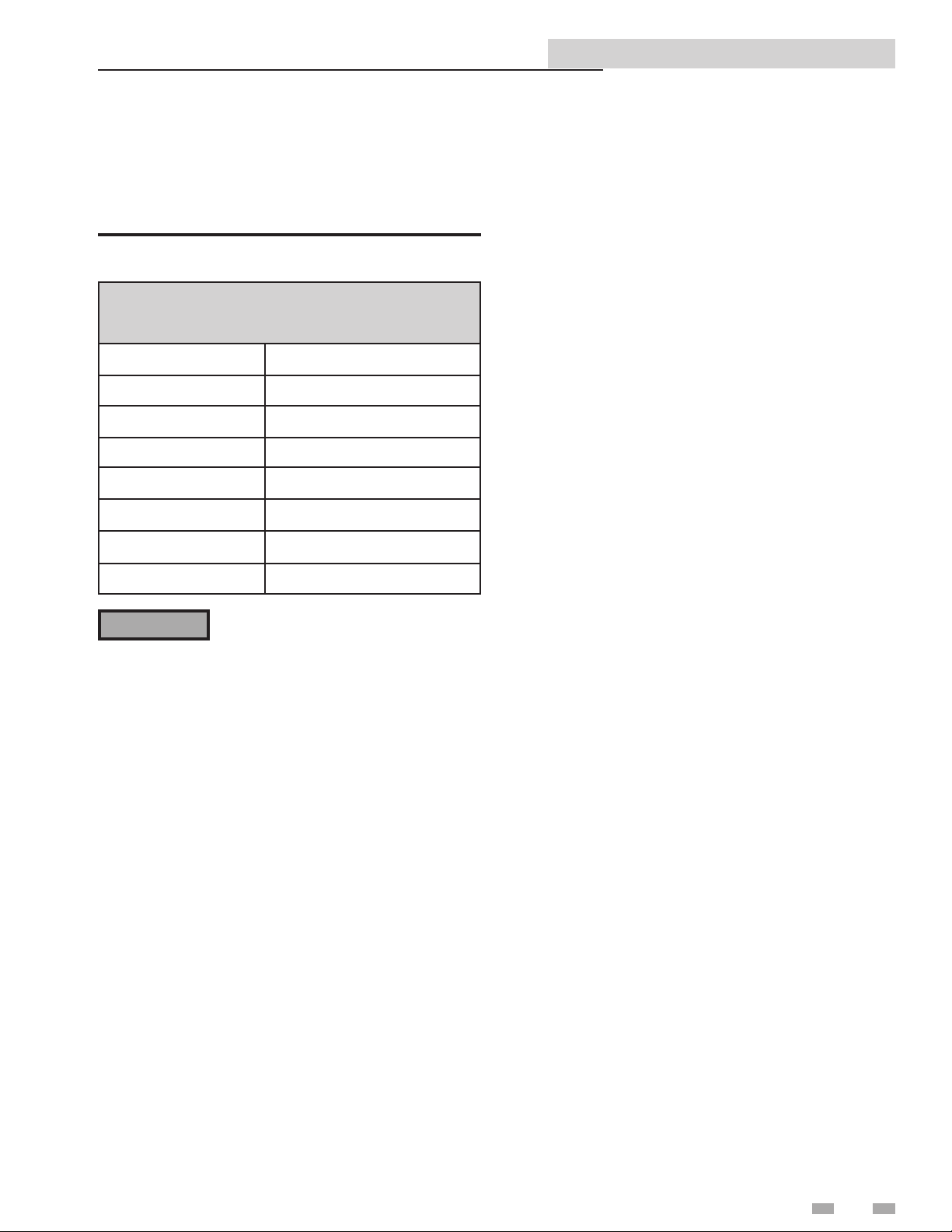
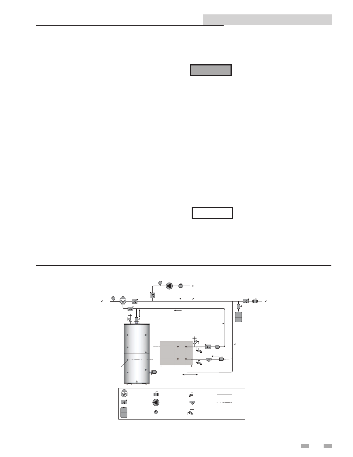
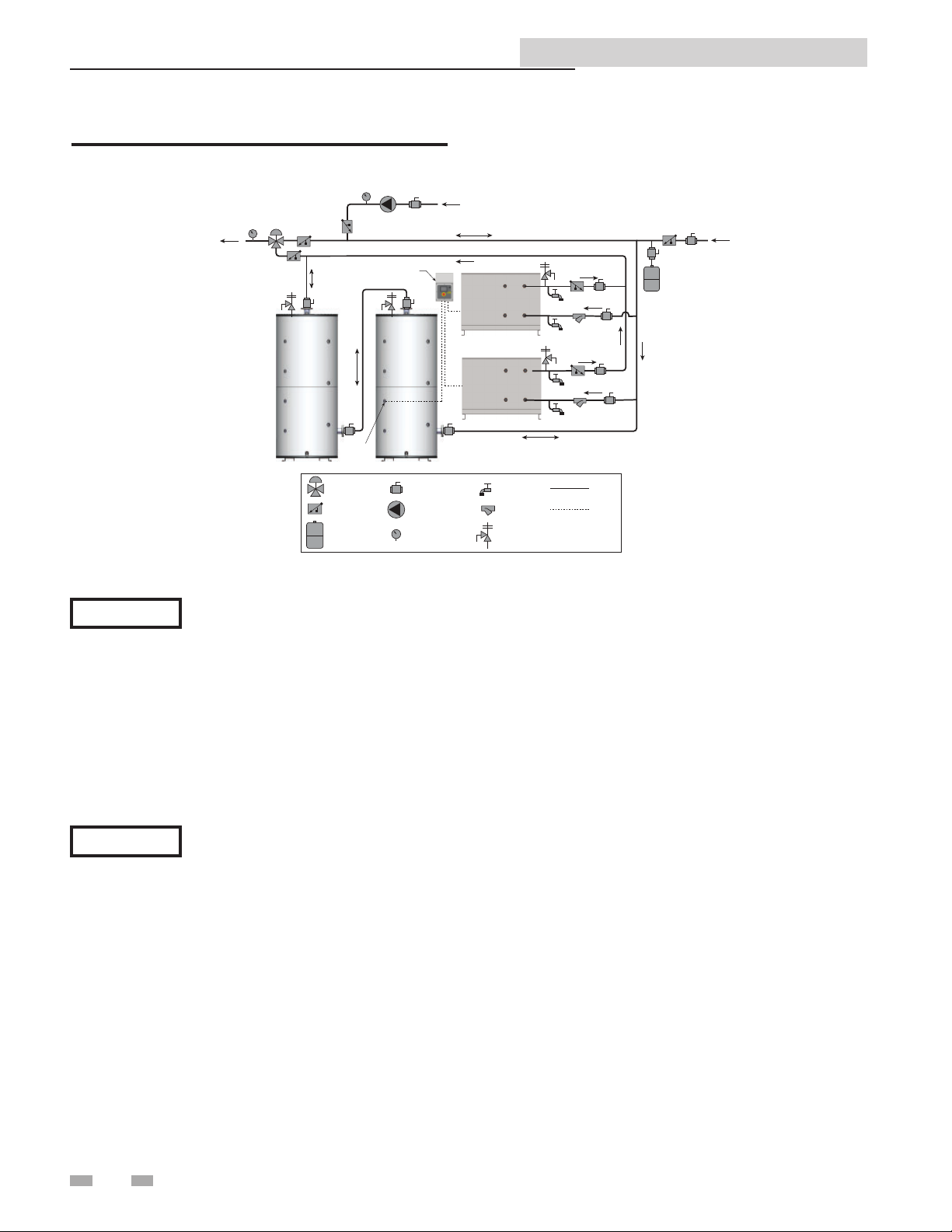
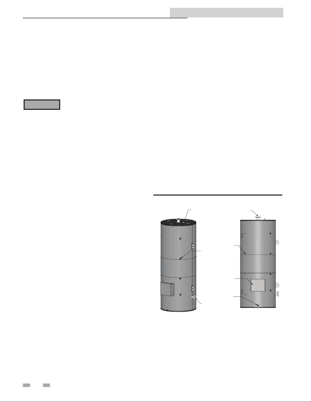
Relief Valve Tapping -- A tapping is provided for the
installation of a field supplied ASME safety relief valve.
Return / Cold Water Supply Tapping -- Lochinvar Heat
Pump Storage Tanks will have one (1) tapping designed to
return cold water back to the heater during the charge cycle
and will allow cold water in during the discharge cycle.
Hot Water Supply / Outlet Tapping -- A Hot Water Supply
/ Outlet Tapping is positioned on the top of the tank for
connection to the hot side of a mixing valve.
Drain -- A tapping or drain pipe will be connected to a low
point on the tank for drainage.
Aquastat Bulbwell -- Lochinvar Heat Pump Storage Tanks
are provided with four (4) super bulbwells for control sensors.
Five-Year Limited Tank Warranty -- Provides warranty
protection against tank failure (see warranty for details).
One-Year Limited Warranty -- Parts and accessories (see
warranty for details).
Areas of potential danger:
1. All water lines, joints, and valves.
2. All power connections and cables.
3. If the unit has been in operation, allow
the water in the heater and all
components and surfaces (tank surface,
water piping, etc.,) to cool before
starting the procedure.
4. Assure that all power to associated water
heating equipment has been shut off
and disconnected before attempting
any procedures.
5. Assure that all incoming and outgoing
water lines have been shut off at the
manual shutoff valves.
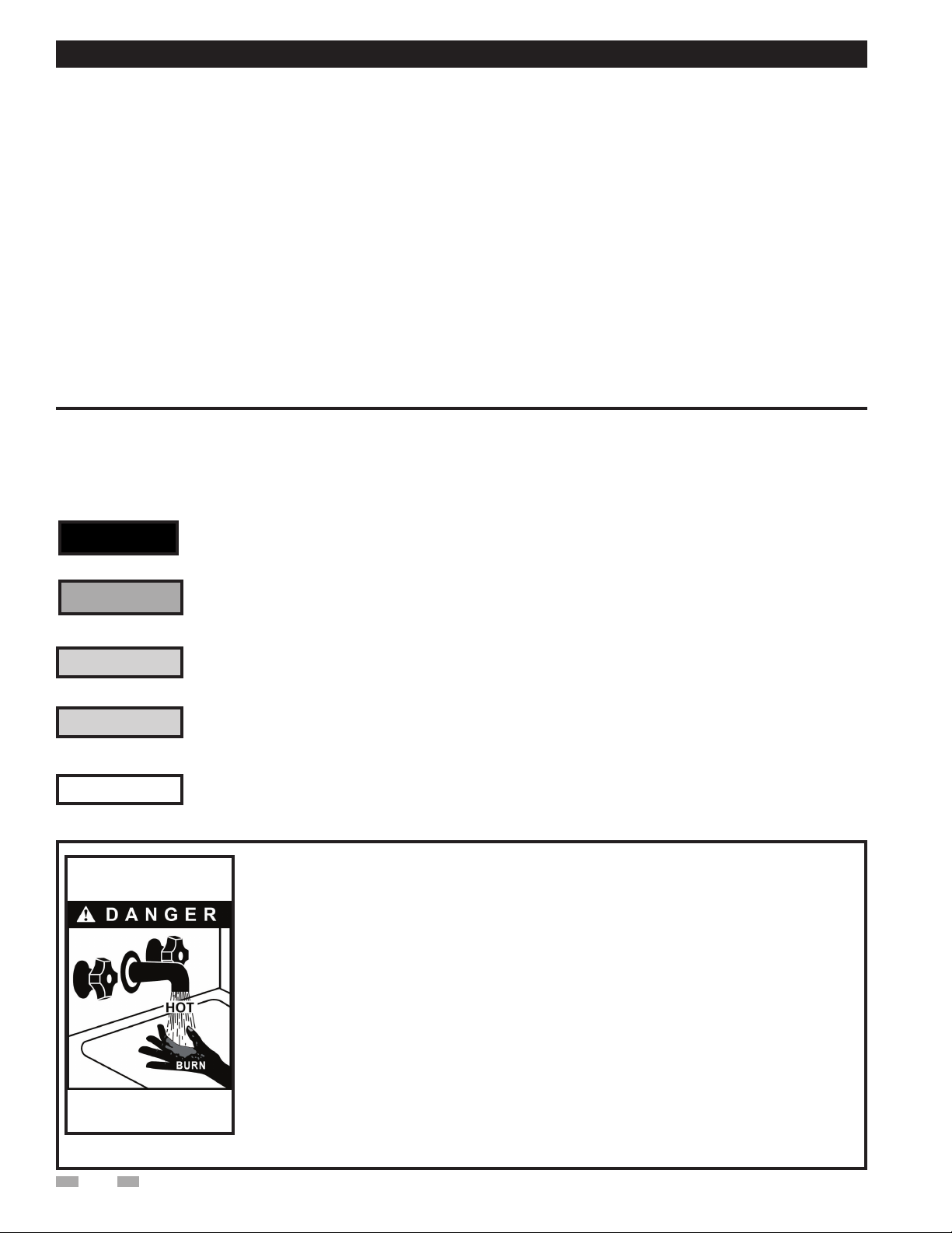
ᘐWARNING Heated water presents situations that can be
very dangerous due to the fact they are under
pressure and at very high temperatures.
To avoid possible injury or death, use
common sense and follow all accepted and
recommended procedures when performing
installation, operation, and maintenance
procedures.
The combination of electricity and water can
pose a very dangerous situation. Assure that
all power has been shut off / disconnected
before attempting any installation or
maintenance procedures.
1 General information
Transporting and unpacking the unit
Each Heat Pump Storage Tank is fitted with lay-down shipping
legs and crated in the horizontal orientation. Crating provides
protection during shipping and a safe means in which to lift and
move the unit with a fork lift.
Remove the crate top and sides but leave the bolted bases in
place until after the unit is lifted into the vertical position.
After the top and sides are removed, the unit should be carefully
examined to assure the tank has not been damaged during
shipping. If any evidence of damage is detected that could affect
the safe operation of the unit, contact Lochinvar, LLC., or your
authorized sales representative, to report the damage and to
receive instructions on how to proceed.
After the unit and all components have been inspected for
damage, it is suggested that all optional or independent pressure
and temperature control components be checked to assure that
they meet or exceed design specifications. If any discrepancy
is found, contact Lochinvar, LLC., or your authorized
representative, before proceeding with the installation.
ᘐWARNING
ᘐWARNING

Storage Tank Installation and Operation Manual
Anchoring the unit
The unit should be anchored to the floor, following applicable
architectural / local code requirements, or accepted standards
for the specific installation site. The unit should be installed
in a location with sufficient clearance for service and repair.
Check local codes for Seismic anchoring requirements. If
further assistance is needed, call the Lochinvar Technical
Service Department and request a Seismic Report.
Before making any connections of water
inlet or outlet to the unit, assure that
all piping is clean and free of foreign
material or scale. This can usually be
accomplished by “blowing out” the pipe.
Any foreign material or scale entering the
unit can adversely affect operation and
performance.
The tapping on the lower side of the vertical tank shall
provide recirculation between the tank and the water heating
source during the charge cycle. During the discharge cycle,
cold water enters the lower tapping to replace hot water
being discharged to the building. See example piping diagram
between a storage tank and a heat pump water heater (FIG.
2-1 and 2-2).
NOTICE See the Water Heater’s Installation and
Operation manual for specific piping
diagrams that match the inlet / outlet
water tappings on the tank to the inlet /
outlet water tappings on the water heater.
Tapping locations on the water heater
may vary by product or manufacturer.
Figure 2-1_Single Pass Piping Diagram - One Heater, One Tank
MIXING VALVE
CHECK VALVE
EXPANSION TANK
ISOLATION VALVE
CIRCULATING PUMP
TEMPERATURE GAUGE
WYE STRAINER
TEMP/PRESS RELIEF
VALVE
FLUSH VALVE PIPING
WIRING
HP WATER HEATER
THERMAL STORAGE
MIXED WATER SUPPLY
TO BUILDING
BUILDING
RECIRC
COLD WATER
SUPPLY
NOTE: DRAWING ILLUSTRATES SUGGESTED PIPING CONFIGURATION
LOCAL CODES AND ORDINANCES MAY HAVE ADDITIONAL REQUIREMENTS
THERMOWELL
THERMAL STORAGE
2 Installation
Connecting the hot water source
ᘐWARNING
The top tapping on the vertical storage tank serves as both
the hot water outlet to the hot side of the mixing valve and a
hot water inlet to receive hot water from the heating source.
A T-junction and a mixing valve are required (FIG. 2-1 and
2-2).
Recommended service clearances:
• 36 inches around the magnesium anode rod(s)
• 24 inches around the manway or inspection hole
5
Transporting and unpacking the
unit (cont'd)
After the unit has been inspected, temporarily remove the
jacket top for unobstructed access to the lifting lugs. Failure
to remove the top during this stand-up procedure can result
in damage to the jacket. Once the unit is in the vertical
position, the remaining crate components can be unbolted
from the shipping legs and bottom channel anchor points.
The shipping legs can be removed by turning counter-
clockwise until detached. Install provided cover-plates over
the shipping leg jacket cut-outs and install the jacket top.
This manual suits for next models
4
Table of contents
Other Lochinvar Water Heater Accessories manuals
Popular Water Heater Accessories manuals by other brands

PAW
PAW K35 Installation and operation instruction

PAW
PAW SolexMini TW Installation and commissioning instructions

Veil
Veil Demi installation guide

Rinnai
Rinnai RGBRE installation instructions

KORADO
KORADO KORAFLEX PM 14 Series Assembly instructions

A.O. Smith
A.O. Smith Product Preservers Powered Anode System user guide