SELECTING A LOCATION
Select a place to install the water heater where water pipes,
electric supply, flue pipe and surrounding surfaces will be
at safe and noise prevention distances.
1. Select a place which is free of moisture, water spills,
pools or snow.
2. Select a place which draining can be done easily.
3. Select a place where the fuel tank can be installed
safely.
4. Select a place where is free of combustible substances.
5. The surrounding walls should be finished with
noncombustible materials (concrete block, mortar, or
plaster are allowable).
6. The floor on which the water heater is installed must
prevent intensive vibrations or shock and must be
strong enough to bear the weight of the water heater.
7. Select a place where proper maintenance and control
can be provided for the unit after installation.
8. Select a place sheltered from weather.
9. Install the unit on a noncombustible surface in a stable
position. In case of installation on combustible floor, the
unit should be raised off the floor to prevent contact
with combustible materials.
10.It is important to keep enough clearance for the
purpose of maintenance, repair and possible servicing.
11. The flue pipe must be free of snow, icing, leaves, bird's
nest or strong drafts.
12. Before making a hole in your wall for the flue pipe,
make sure the area is free of electrical wires, gas pipes
and other obstacles.
13. When installing the horizontal pipe, be careful taken not
to have any convexed or concaved portions in the
pipings, which may cause abnormal combustion or
ignition failure.
INSTALLATION OF UNIT
1. Install the unit on a noncombustible surface in a stable
position. If installing on a combustible floor, the unit
should be raised off floor to prevent contact with
combustible materials.
If minimum clearances between the unit and
combustible construction are maintained, no ventilation
openings are needed in the closet door when installed
in a closet.
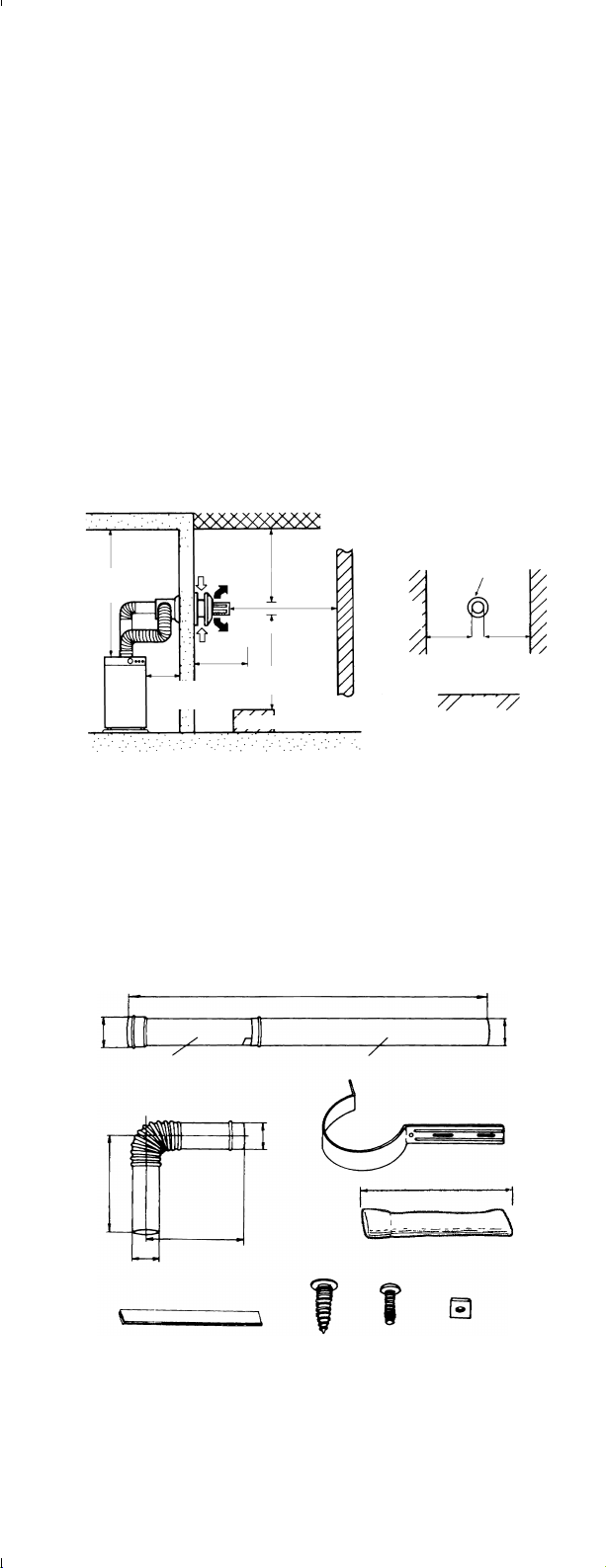
●UNIT (INDOOR CLEARANCE)
Left side 8 in. (205 mm)
Right side 8 in. (205 mm)
Rear side 8 in. (205 mm)
From front door to closet 8 in. (205 mm)
Top 2 ft. (600 mm)
Note: It is important to keep enough clearance for the
purpose of maintenance, repair and possible
servicing.
●FLUE PIPE (OUTSIDE CLEARANCE)
From flue pipe top to combustible surface:
Vertical 24 in.(600 mm)
From flue pipe top to combustible surface:
Horizontal 24 in.(600 mm)
2. Check local codes regarding installation of the water
heater, water piping and fuel tank.
UNPACKING
Check the following parts provided before installing.
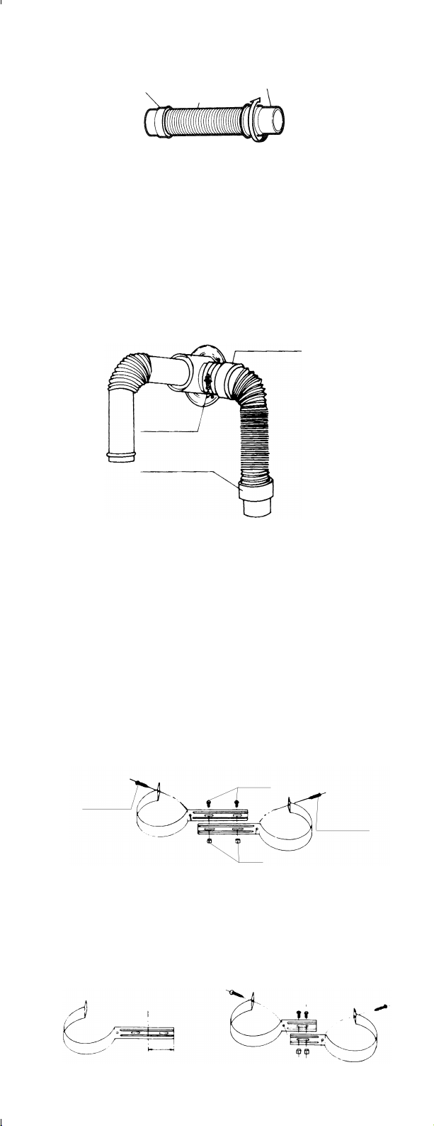
INSTALLATION OF FLUE PIPE
IMPORTANT: Check and comply with all state and local
codes that may apply to water heater before
beginning installation.
31-3/4"〜57"(805〜1450mm)
Extension pipe "A" (2pcs.)
Extension pipe "B" (2pcs.)
Bent joint
(2pcs.)
Pipe support bracket (4pcs.)
Φ2-3/4"
(Φ70mm)
Φ2-13/16"
(Φ71mm)
Φ2-13/16"
(Φ71mm)
5-7/8"
(150mm)
5-7/8"
(150mm)
Self tapping
screw(5pcs.)
Screw
(4pcs.)
Nut
(4pcs.)
Φ2-3/4"
(Φ70mm)
Aluminum tape
(2pcs.)
Insulating cloth cover 3-1/3"(Φ80mm)(2pcs.)
(Part#20476455)
39-3/8"(1000mm)
Combustible object
Flue pipe top
more than 2ft.
(60cm)
more than 2ft.
(60cm)
more than 8 in.
(205cm)
more
than 2ft.
(60cm)
more than 2ft.
(60cm)
more than
2ft.(60cm)
more than
2ft.(60cm)
Intake
air
Intake
air
Combustible object
Combustible
object
Exhaust
gas
Exhaust
gas
Combustible
object
1. Select unit location. Allow clearances as indicated
above between the unit and all other materials.
2. Make sure that the outside area to where the flue pipe
will reach is clear of any objects.
NOTE: Make sure wall thickness is not greater than 10
inches.
Flue pipe can be installed through any standard
building materials. Please ask your local dealer
or distributor for more details.
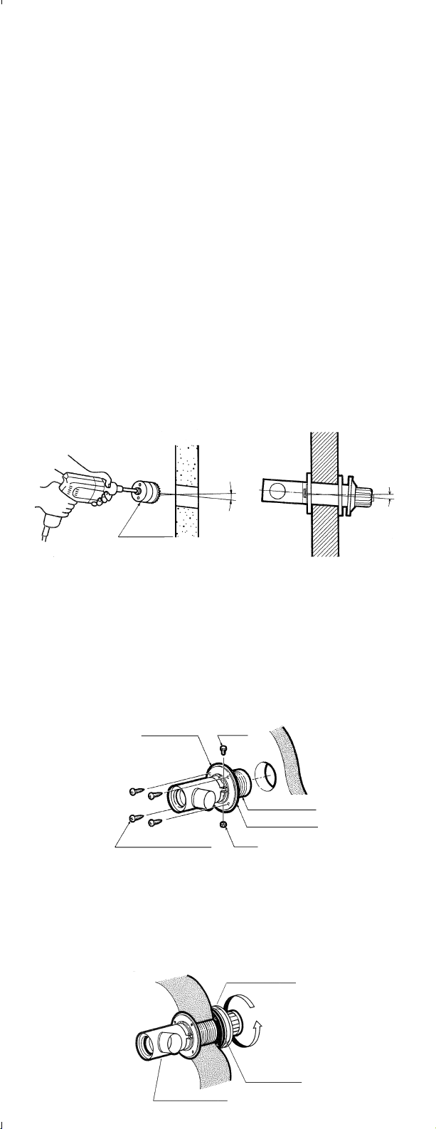
3. Position the hole for the flue pipe.
4. Cut the hole for the flue pipe from inside the room. Use
a 4-3/4" diameter hole saw attached to an electric drill.
The opening on the inside wall should be slightly
higher than the outside opening (approximately 1/4") so
that the flue pipe will slope slightly downward
(approximately 3 degrees) after it is installed. This will
enable condensed moisture to drain from the flue pipe
to the outside and prevent rain or snow from entering
from outside after installation.
5. Install the inner flange and the flange gasket to the
inner flue pipe and insert the inner flue pipe through
the wall hole from inside the room. Make sure the
arrow on the inner flange is pointing up and secure the
securing band with a screw and a nut through two
holes of the locking band. Secure the inner flue pipe to
the wall with the four screws provided with the unit.
6. Install the flange gasket to the outer flue pipe. Secure
the outer flue pipe to the wall by turning it clockwise.
This locks the two halves together.
NOTE: Make sure to secure the outer flue pipe well.
Outer flue pipe
Flange
gasket
Inner flue pipe
Inner flange
Self tapping screw Nut
Inner flue pipe
Flange gasket
screw
SAFETY TIPS FOR INSTALLATION
Follow the safety tips below and read the installation
manual provided with the unit when planning the
installation of your water heater.
WARNING
1. The flue pipe opening must be fully exposed to outside
air. Do not vent into a garage, basement under the
floor, or into any enclosed area.
2. Do not install the flue pipe in close proximity to other
objects or materials.
3. Before making a hole in your wall for the flue pipe,
make sure the area is free of electrical wires, gas pipes
and other obstacles.
4. Do not install the flue pipe where it will be exposed to
heavy snow, collected leaves, or strong drafts.
IMPORTANT: In areas of heavy snow fall, ground
surface clearance must be increased
according to average snow falls.
In open areas with strong wind, a wind
break may be necessary.
5. Do not install the flue pipe below the water heater nor
into a chimney.
6. The exhaust pipe should be properly installed and
connected. Aluminum tape may be used for sealing
exhaust pipe connections.
7. This unit must be installed in accordance with these
instructions, local codes, ordinance and/or in the
absence of local codes, the latest edition of the national
fire protection association (NFPA31) code.
8. Check and comply with all state, local codes and ANSI
Z21.22 that may apply to water heater(s) before
beginning the installation.
This unit should be installed by a licensed, authorized
person(s) due to the necessity of making electrical,
water and fuel connections.
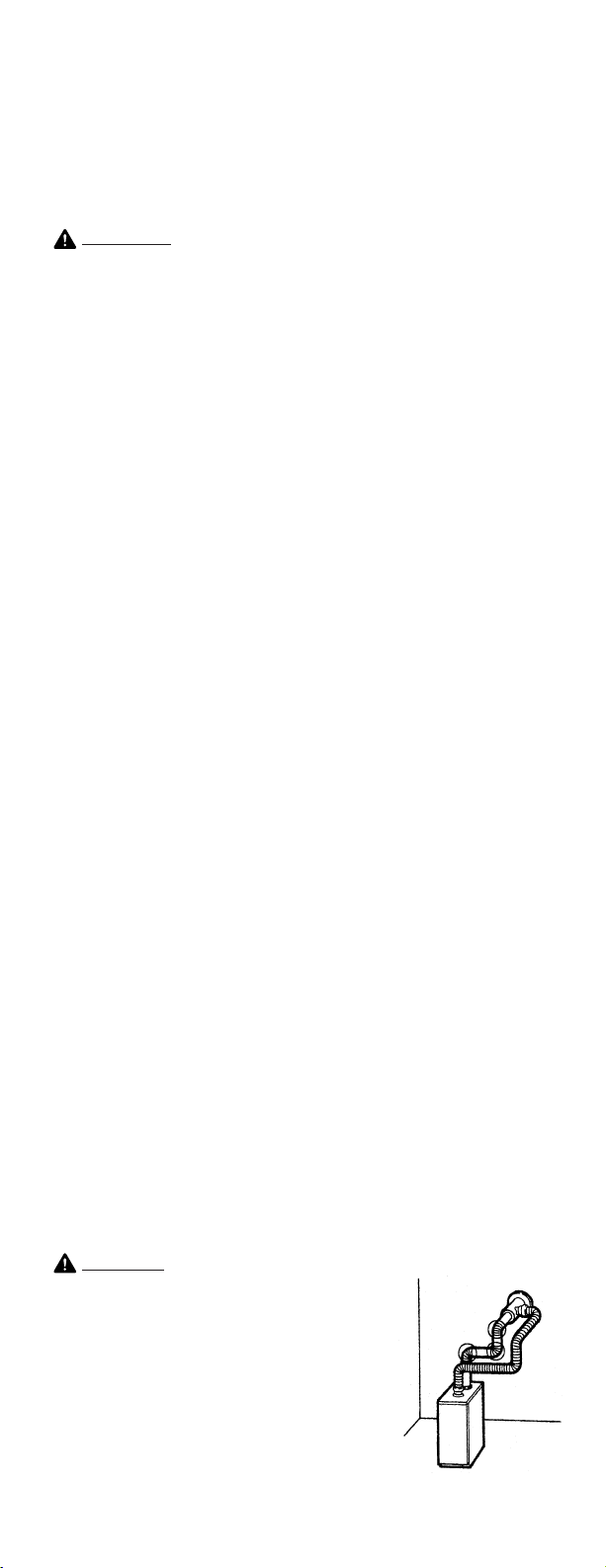
CAUTION
Total length of the extension pipe
between the water heater and the flue
pipe must be no greater than 10 ft. and
three bends may be used.
NOTE: When using extension pipes
always cover the exhaust pipe
with the insulating cloth cover.