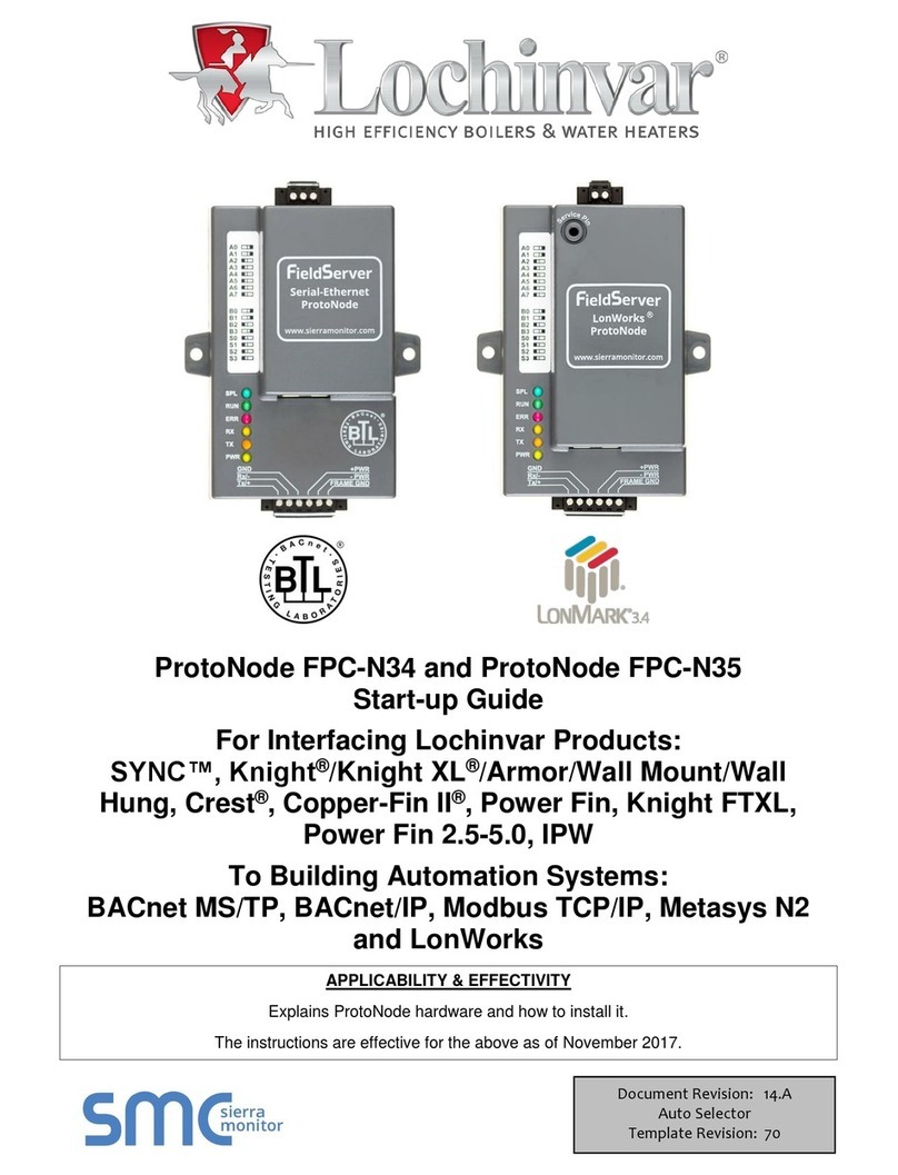
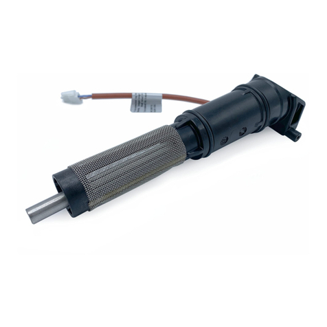
Lochinvar ProtoNode FPC-N35 User guide

ProtoNodeFPC‐N34andProtoNode
FPC‐N35
Startup
Guide
ForInterfacingLochinvar
Products:
Lochinvar’sArmor®,SYNC™/ArmorX2,Knight®/KnightXL®,
FTXL,
Crest®,Copper‐FinII®andPowerFin
boilers
ToBuildingAutomation
Systems:
BACnetMS/TP,BACnet/IP,ModbusTCP/IP,MetasysN2
and
LonWorks
APPLICABILITY&EFFECTIVITY
ExplainsProtoNodeFPC‐N34andFPC‐N35hardwareandhowtoinstallit.
TheinstructionsareeffectivefortheaboveasofAugust2014
DocumentRevision:
10
Auto
Selector
TemplateRevision:
23

INS70085LochinvarProtoNodeStartupGuide Page2 o
f
48
ProtoCessor1991TarobCourtMilpitas, California 95035 USA Web:
www.ProtoCessor.com
Email:
Support@ProtoCessor.com
TechnicalSupport:
ThankyouforpurchasingtheProtoNodeforLochinvarBoilers.
PleasecallLochinvarforTechnicalsupportoftheProtoNodeproduct.
FieldServerdoesnotprovidedirectsupport. IfLochinvarneedstoescalatetheconcern,theywillcontact
FieldServerforassistance.
SupportContactInformation:
Lochinvar,LLC
300MaddoxSimpsonPkwy.
Lebanon,TN37090
LochinvarService:
1‐800‐722‐2101
Email:2tec[email protected]
Website:www.lochinvar.com

INS70085LochinvarProtoNodeStartupGuide Page3 o
f
48
ProtoCessor1991TarobCourtMilpitas, California 95035 USA Web:
www.ProtoCessor.com
Email:
Support@ProtoCessor.com
AQuickStart
guide
1.Recordtheinformationabouttheunit.(Section2.1)
2.Setthedevice’sModbusRTUserialsettings(i.e.baudrate,parity,stopbits)andModbusNode‐IDforeach
ofthedevicesthatwillbeconnectedtoProtoNodeFPC‐N34orFPC‐N35.(Section2.2)
3.SelectastoredconfigurationandsetfieldprotocolMACaddress/Node‐ID/DeviceInstance,andbaudrate.
(Section2.3)
4.ConnectProtoNode’s6pinRS‐485connectortotheModbusRS‐485networkthatisconnectedtoeachof
thedevices.(Section3.2)
5.ConnectFPC‐N34ProtoNode’s3pinRS‐485porttotheFieldProtocolcabling,
orconnectFPC‐N35ProtoNode’s2pinLonWorksporttotheFieldProtocolcabling.(Section3.4)
6.ConnectPowertoProtoNode’s6pinconnector.(Section3.5)
7.BACnet/IPorModbusTCP/IP/IP(FPC‐N34):UsetheProtoNode’sembeddedtoolwhichisaccessedwitha
browser,referredtointhismanualastheWebConfigurator,tochangetheIPaddress.Nochangestothe
configurationfilearenecessary.(Section4)
8.LonWorks(FPC‐N35):TheProtoNodemustbecommissionedontheLonWorksNetwork.Thisneedstobe
donebytheLonWorksadministratorusingaLonWorksCommissioningtool.(Section6)

INS70085LochinvarProtoNodeStartupGuide Page4 o
f
48
ProtoCessor1991TarobCourtMilpitas, California 95035 USA Web:
www.ProtoCessor.com
Email:
Support@ProtoCessor.com
Certifications
BTLMARK– BACNETTESTING
LAB
O
R
ATORY
TheBTLMarkonProtoNodeFPC‐N34isasymbolthatindicatesthataproducthas
passedaseriesofrigoroustestsconductedbyanindependentlaboratorywhich
verifiesthattheproductcorrectlyimplementstheBACnetfeaturesclaimedinthe
listing.Themarkisasymbolofahigh‐qualityBACnetproduct.Goto
http://www.bacnetinternational.net/btl/formoreinformationabouttheBACnet
TestingLaboratory.
LONMARKC
ER
T
IFI
C
A
T
I
ON
LonMarkInternationalistherecognizedauthorityforcertification,education,and
promotionofinteroperabilitystandardsforthebenefitofmanufacturers,integrators
andendusers.LonMarkInternationalhasdevelopedextensiveproductcertification
standardsandteststoprovidetheintegratoranduserwithconfidencethatproducts
frommultiplemanufacturersutilizingLonMarkdevicesworktogether.FieldServer
TechnologieshasmoreLonMarkCertifiedgatewaysthananyothergateway
manufacturer,includingtheProtoCessor,ProtoCarrierandProtoNodeforOEM
applicationsandthefullfeatured,configurablegateways.

INS70085LochinvarProtoNodeStartupGuide Page5 o
f
48
ProtoCessor1991TarobCourtMilpitas, California 95035 USA Web:
www.ProtoCessor.com
Email:
Support@ProtoCessor.com
TABLEOFCONTENTS
1
Introduction
...................................................................................................................................................
7
1.1ProtoNodeGateway......................................................................................................................................7
2BACnet/LonWorksSetupforProtoCessorProtoNode
FPC‐N34/FPC‐N35.......................................................
7
2.1RecordIdentification
Data
.............................................................................................................................7
2.2ConfiguringDevice
Communications
.............................................................................................................7
2.2.1SetModbusCOMsettingonallofthedevicesconnectedtotheProtoNode
..........................................7
2.2.2SetModbusRTUNode‐IDforeachofthedevicesattachedtothe
ProtoNode........................................8
2.3SelectingStoredConfigurations,SettingtheMacAddress,DeviceInstance,Node_ID,andBaud
Rate
.......9
2.3.1SelectingConfigurationFilesforDevices:“S”bankDIPSwitchesS0–
S3
................................................9
2.3.1.1BACnetMS/TPandBACnetIPDIPSwitchSettings
.........................................................................9
2.3.1.2LonWorksDIPSwitchSettings
......................................................................................................11
2.3.2BACnetMS/TP(FPC‐N34):SettingtheMACAddressBACnet
Networks................................................11
2.3.3BACnetMS/TPandBACnet/IP(FPC‐N34):SettingtheDevice
Instance.................................................12
2.3.3.1BACnetMS/TPorBACnet/IP:AssigningSpecificDeviceInstances
..............................................12
2.3.4MetasysN2andModbusTCP/IP(FPC‐N34):Settingthe
Node‐ID
.........................................................12
2.3.5BACnetMS/TP(FPC‐N34):SettingtheSerialBaudRate(DIPSwitchB0–
B3).......................................13
2.3.5.1BaudRateDIPSwitchSelection
....................................................................................................13
3InterfacingProtoNodetoDevices
................................................................................................................14
3.1ProtoNodeFPC‐N34andFPC‐N35ShowingConnection
Ports
....................................................................14
3.2DeviceConnectionstoProtoNode...............................................................................................................15
3.2.1EndofLineTerminationSwitchfortheModbusRS‐485portonthe
ProtoNode
...................................16
3.2.2Lochinvar’sArmor,SYNC/ArmorX2,Knight/KnightXL,Crest,Copper‐FinIIandFTXLLowVoltage
ModbusRTUConnectionWiringtothe
ProtoNode:
............................................................................................17
3.3BACnetMS/TPorMetasysN2(FPC‐N34):WiringFieldPorttoRS‐485
Network
........................................18
3.4LonWorks(FPC‐N35):WiringFieldPorttoLonWorksNetwork..................................................................19
3.5ConnectingPowerto
ProtoNode
.................................................................................................................20
4
B
ACnet/IPandModbusTCP/IP:ChangetheProtonodeIP
Address..............................................................
21
4.1ConnectthePCtoProtoNodeviathe Ethernet
Port
...................................................................................21
4.2BACnetMS/
T
PandBACnet/IP:Setting Node
_
Offset to Assign Specific Device Instances.........................22
4.3AccessingtheFS
T
WebGUIfromthe Web Configurator ............................................................................23
4.4BACnet/IPandModbusTCP/IP:Setting IP Address for Field
Network
........................................................24
5Howtostarttheinstallationover:clearingprofiles
.....................................................................................
25
6LonWorks(FPC‐N35):CommissioningProtoNodeonaLonWorks
Network..................................................
26
6.1CommissioningProtoNodeFPC‐N35onaLonWorksNetwork...................................................................26
6.1.1InstructionstoUploadXIFFilefromProtoNodeFPC‐N35UsingFSGUIWeb
Server
.............................26
7CASBACnetExplorerforValidatingProtoNodeintheField
.........................................................................
28
7.1DownloadingtheCASExplorerandRequestinganActivationKey.............................................................28
7.2CASBACnet
Setup
........................................................................................................................................29
7.2.1CASBACnetMS/TPSetup.......................................................................................................................29
7.2.2CASBACnetBACnet/IP
Setup
.................................................................................................................29
AppendixA.Troubleshooting
..............................................................................................................................
30
AppendixA.1.ViewingDiagnostic
information
.......................................................................................................30
AppendixA.2.CheckWiringandSettings................................................................................................................31
AppendixA.3.TakeDiagnosticCaptureWiththeFieldServerUtilities...................................................................31
AppendixA.4.BACnet/IP:SettingNetwork_NumberformorethanoneProtoNodeonSubnet...........................34
AppendixA.5.LEDDiagnosticsforModbusRTUCommunicationsBetweenProtoNodeand
Devices
...................34
AppendixB.VendorInformation‐
Lochinvar
.......................................................................................................
35
AppendixB.1.SyncModbusRTUMappingstoBACnetMS/TP,BACnet/IP,MetasysN2and
LonWorks
................35
AppendixB.2.KnightModbusRTUMappingstoBACnetMS/TP,BACnet/IP,MetasysN2and
LonWorks
.............36

INS70085LochinvarProtoNodeStartupGuide Page6 o
f
48
ProtoCessor1991TarobCourtMilpitas, California 95035 USA Web:
www.ProtoCessor.com
Email:
Support@ProtoCessor.com
AppendixB.3.CrestModbusRTUMappingstoBACnetMS/TP,BACnet/IP,MetasysN2and
LonWorks
...............38
AppendixB.4.Copper‐FinIIModbusRTUMappingstoBACnetMS/TP,BACnet/IP,MetasysN2andLonWorks..39
AppendixB.5.PowerFinModbusRTUMappingstoBACnetMS/TP,BACnet/IP,MetasysN2and
LonWorks
.......41
AppendixB.6.FTXLModbusRTUMappingstoBACnetMS/TP,BACnet/IP,MetasysN2andLonWorks................42
AppendixC.“A”BankDIPSwitchSettings
...........................................................................................................
44
AppendixC.1.“A”BankDIPSwitchSettingsforMACAddressor
Node‐ID
.............................................................44
AppendixD.Reference
........................................................................................................................................
47
AppendixD.1.Specifications...................................................................................................................................47
AppendixD.1.1.CompliancewithULRegulations............................................................................................47
AppendixE.Limited2YearWarranty
..................................................................................................................
48
LISTOFFIGURES
Figure1:ProtoCessorPartNumbers.............................................................................................................................7
Figure2:ModbusRTUCOMSettings............................................................................................................................7
Figure3:Lochinvar’sModbusCOMboardshowingserialDIP
Switches
.......................................................................8
Figure4:SBankDIP
Switches
........................................................................................................................................9
Figure5:LocationforProtoCessorsmallABankofDIPswitches...............................................................................10
Figure6:MACAddressDIP
Switches
...........................................................................................................................11
Figure7:BaudRateDIP
Switches
................................................................................................................................13
Figure8:BaudRate......................................................................................................................................................13
Figure9:ProtoNodeBACnetFPC‐N34(upper)andProtoNodeFPC‐N35(lower).......................................................14
Figure10:PowerandRS‐485
Connections
..................................................................................................................15
Figure11:ModbusRS‐485End‐Of‐LineTerminationSwitchontheProtoNodeN34(left)and.................................16
Figure12:LowVoltageModbusRTUConnectionWiringtotheProtoNode..............................................................17
Figure13:ConnectionfromProtoNodetoRS‐485FieldNetwork..............................................................................18
Figure14:RS‐485EOLSwitch......................................................................................................................................18
Figure15:LonWorks
Terminal
.....................................................................................................................................19
Figure16:Requiredcurrentdrawforthe
ProtoNode
................................................................................................20
Figure17:Power
Connections
.....................................................................................................................................20
Figure18:WebConfiguratorscreen............................................................................................................................22
Figure19:WebConfiguratorscreenwithActiveProfiles............................................................................................23
Figure20:ChangingIPAddressviaFSTWeb
GUI
........................................................................................................24
Figure21:LonWorksServicePin
Location
...................................................................................................................26
Figure22:SampleofFserver.XIFFileBeing
Generated
...............................................................................................27
Figure23:DownloadingtheCAS
Explorer
...................................................................................................................28
Figure24:RequestingCASActivation
Key
...................................................................................................................28
Figure25:ViewingDiagnostic
Errors
...........................................................................................................................30
Figure26:EthernetPortLocation................................................................................................................................31
Figure27:WebConfiguratorshowingsettingthenetworknumberforBACnet/IP...................................................34
Figure28:Diagnostic
LEDs
...........................................................................................................................................34
Figure29:
Specifications
..............................................................................................................................................47

INS70085LochinvarProtoNodeStartupGuide Page7 o
f
48
ProtoCessor1991TarobCourtMilpitas, California 95035 USA Web:
www.ProtoCessor.com
Email:
Support@ProtoCessor.com
1INTRODUCTION
1.1ProtoNodeGateway
ProtoNodeisanexternal,highperformanceBuildingAutomationmulti‐protocolgatewaythathasbeen
preprogrammedforLochinvar’sproducts(hereaftercalled“device”)tovariousbuildingautomation
protocols. TheseprotocolsincludeBACnet®1MS/TP,BACnet/IP,Metasys®2N2byJCI,ModbusTCP/IP,and
LonWorks®3.ConfigurationsforthevariousprotocolsarestoredwithintheProtoNodeandareselectablevia
DIPswitchesforfastandeasyinstallation.
Itisnotnecessarytodownloadanyconfigurationfilestosupporttherequiredapplications.
2BACNET/LONWORKSSETUPFORPROTOCESSORPROTONODEFPC‐ N34/FPC‐ N35
2.1RecordIdentificationData
EachProtoNodehasauniquepartnumberlocatedontheundersideoftheunit.Thisnumbershouldbe
recorded,asitmayberequiredfortechnicalsupport.Thenumbersareasfollows:
Model
PartNumber
ProtoNodeFPC‐N34FPC‐N34‐0614
ProtoNodeFPC‐N35FPC‐N35‐103‐401‐0615
Figure1:ProtoCessorPartNumbers
FPC‐N34unitshavethefollowing3ports:RS‐485+Ethernet+RS‐485.
FPC‐N35unitshavethefollowing3ports:LonWorks+Ethernet+RS‐485
2.2ConfiguringDeviceCommunications
2.2.1SetModbusCOMsettingonallofthedevicesconnectedtotheProtoNode
SeteachLochinvarDevice’sModbus RTU COM setting to match Figure 2viatheDIPswitches on the
Device’sModbuscard.
SettheDIPswitch1toONand2‐10toOFFpositionontheModbusCOMboard.ThiswillsettheLochinvar
boilerfor9600,8,2,N,andNode‐IDof1.(Seefigure3)
SerialPortSetting
Device
ProtocolModbusRTU
BaudRate9600
ParityNone
DataBits8
StopBits2
Figure2:ModbusRTUCOMSettings
1BACnetisaregisteredtrademarkofASHRAE
2MetasysisaregisteredtrademarkofJohnsonControlsInc.
4LonWorksisaregisteredtrademarkofEchelonCorporation

INS70085LochinvarProtoNodeStartupGuide Page8 o
f
48
ProtoCessor1991TarobCourtMilpitas, California 95035 USA Web:
www.ProtoCessor.com
Email:
Support@ProtoCessor.com
Figure3:Lochinvar’sModbusCOMboardshowingserialDIPSwitches
2.2.2SetModbusRTUNode‐ IDforeachofthedevicesattachedtotheProtoNode
SettheModbusNode‐IDforeachofthedevicesattachedtoProtoNode.
TheModbusNode‐ID’sneedtobeuniquelyassigned,startingwithavalueof1forthefirstdevice.
ModbusNode‐IDvaluesforadditionaldevicesmustbesequential(2,3,4,…).

INS70085LochinvarProtoNodeStartupGuide Page9 o
f
48
ProtoCessor1991TarobCourtMilpitas, California 95035 USA Web:
www.ProtoCessor.com
Email:
Support@ProtoCessor.com
2.3SelectingStoredConfigurations,SettingtheMacAddress,DeviceInstance,
Node_ID,andBaudRate
2.3.1SelectingConfigurationFilesforDevices:“S”bankDIPSwitchesS0–S3
TheSbankofDIPswitches(S0‐S3)areusedtoselectandloadaconfigurationfilefromagroupof
pretested/preloadedconfigurationfileswhicharestoredintheProtoNodeFPC‐N34(BACnetMS/TP,
BACnet/IP,ModbusTCP/IP,MetasysN2)andtheProtoNodeFPC‐N35(LonWorks).
S0 S1 S2
S3
S0–S3DIPSwitches
SBankDIPSwitchLocation
Figure4:SBankDIP
Swit
c
h
e
s
2.3.
1.1
BACn
et
MS/
TPand
BA
CnetIPDIPSwitch
Sett
ing
s
ThefollowingchartdescribesS0‐S3DIPSwitchconfigurationsettingsfordeviceapplicationstosupport
BACnetMS/TPandBACnet/IPonaProtoNodeFPC‐N34
TosetSYNC,Knight/KnightXL/Armor/WallMount/WallHung,Crest,Copper‐FinII,PowerFinandFTXLDIP
switchsettings,thecoverdoesnotneedtoberemoved.TheProtoCessorSmallABankofDIPswitchesare
alloff.Thisthedefaultpositionwhenshipped.
RemovetheProtoNodecovertosetProtoCessorSmallDIPswitchsettings.(SeeFigure3)
Cover
doesn’t
need
to
be
Removed
ProtoCarrierDIPSwitches
Profile‐FPC‐N34‐0614
S0
S1
S2
S3
BACnetIP/BACnetMS
T
P/Modbus TCP/IP SYNC Deg
_
COff Off OffOff
BACnetIP/BACnetMS
T
P/Modbus TCP/IP Knight/Knight
XL/Armor/WallMount/WallHungDeg_C
On Off OffOff
BACnetIP/BACnetMS
T
P/Modbus TCP/IPCrest Deg
_
COffOnOffOff
BACnetIP/BACnetMS
T
P/Modbus TCP/IPCopper‐Fin II Deg_COnOnOffOff
BACnetIP/BACnetMS
T
P/Modbus TCP/IP Power Fin Deg
_
COffOffOnOff
BACnetIP/BACnetMS
T
P/Modbus TCP/IP F
T
XL Deg
_
COnOffOnOff
BACnetIP/BACnetMS
T
P/Modbus TCP/IP SYNC Deg
_
FOffOnOnOff
BACnetIP/BACnetMS
T
P/Modbus TCP/IP Knight/Knight
XL/Armor/WallMount/WallHungDeg_F
OnOnOnOff
BACnetIP/BACnetMS
T
P/Modbus TCP/IPCrest Deg
_
FOffOffOffOn
BACnetIP/BACnetMS
T
P/Modbus TCP/IPCopper‐Fin II Deg_FOnOffOffOn
BACnetIP/BACnetMS
T
P/Modbus TCP/IP Power Fin Deg
_
FOffOnOffOn
BACnetIP/BACnetMS
T
P/Modbus TCP/IP F
T
XL Deg
_
FOnOnOffOn

INS70085LochinvarProtoNodeStartupGuide Page10 o
f
48
ProtoCessor1991TarobCourtMilpitas, California 95035 USA Web:
www.ProtoCessor.com
Email:
Support@ProtoCessor.com
RemoveCovertoSelectA‐BankDIPSwitchesS0S1S2S3A1A2A3A4A5A6A7A8
MetasysN2SYNCDeg
_
COffOffOnOnOffOffOffOffOffOffOffOff
MetasysN2Knight/KnightXL/Armor/Wall
Mount/WallHungDeg_C
OnOffOnOnOffOffOffOffOffOffOffOff
MetasysN2CrestDeg
_
COffOnOnOnOffOffOffOffOffOffOffOff
MetasysN2Copper‐FinIIDeg
_
COn On On On Off Off OffOffOffOff Off Off
MetasysN2PowerFinDeg
_
COff Off Off Off On Off OffOffOffOff Off Off
MetasysN2F
T
XLDeg
_
COn Off Off Off On Off OffOffOffOff Off Off
MetasysN2SYNCDeg
_
FOff On Off Off On Off OffOffOffOff Off Off
MetasysN2Knight/KnightXL/Armor/Wall
Mount/WallHungDeg_F
On On Off Off On Off OffOffOffOff Off Off
MetasysN2CrestDeg
_
FOffOffOnOffOnOffOffOffOffOffOffOff
MetasysN2Copper‐FinIIDeg
_
FOnOffOnOffOnOffOffOffOffOffOffOff
MetasysN2PowerFinDeg
_
FOffOnOnOffOnOffOffOffOffOffOffOff
MetasysN2F
T
XLDeg
_
FOnOnOnOffOnOffOffOffOffOffOffOff
Tosetselecttheseconfigurations,opentheProtoNodeandselecttheAbankofswitches(A1orA2orA3)
onthesmallProtoCessormodulethatsitsontopoftheProtoCarrier(insidetheProtoNode).
ProtoCessorA1DIPswitchstartsonthebottomoftheAbankofDIPswitchesbelow.
ProtoCessorA3‐A8DIPswitchesaredisabled.
A1andA2DIPSwitches
SBankDIPSwitches
Figure5:LocationforProtoCessorsmallABankofDIPswitches
NOTE:WhensettingDIPSwitches,pleaseensurethatpowertotheboardisOFF.

INS70085LochinvarProtoNodeStartupGuide Page11 o
f
48
ProtoCessor1991TarobCourtMilpitas, California 95035 USA Web:
www.ProtoCessor.com
Email:
Support@ProtoCessor.com
2.3.
1.2
LonWork
s
DI
P
S
wit
ch
S
etti
ngs
ThefollowingchartdescribestheDIPswitchsettingstosupportLonWorksonaProtoNodeFPC‐N35.
Profile‐FPC‐N35‐103‐401‐0615
S0
S1
S2
S3
LonWorksSYNCOffOffOffOff
LonWorksKnight/KnightXL/Armor/Wall Mount/Wall HungOnOffOffOff
LonWorksCrestOffOnOffOff
LonWorksCopper‐FinIIOnOnOffOff
LonWorksPowerFinOffOffOnOff
LonWorksF
T
XLOnOffOnOff
NOTE:WhensettingDIPSwitches,pleaseensurethatpowertotheboardis
OFF.
2.3.2BACnetMS/TP(FPC‐ N34):SettingtheMACAddressBACnetNetworks
Only1 MACaddressissetforProtoNoderegardlessofhowmanydevicesareconnectedto
ProtoNode.
SettheBACnetMS/TPMACaddressesoftheProtoNodetoavaluebetween1to127(MACMaster
Addresses);thisissothattheBMSFrontEndcanfindtheProtoNodeviaBACnetauto
discovery.
Note:NeversetaBACnetMS/TPMACAddressfrom128to255. Addressesfrom128to255are
SlaveAddressesandcannotbediscoveredbyBMSFrontEndsthatsupportautodiscoveryofBACnet
MS/TPdevices.
SetDIPswitchesA0–A7toassignMACAddressforBACnetMS/TPfortheProtoNodeFPC‐N34.
PleaserefertoAppendixC.1forthecompleterangeofMACAddressesandDIPswitchsettings.
Figure6:MACAddressDIP
Swi
tc
h
e
s
NOTE:WhensettingDIPSwitches,pleaseensurethatpowertotheboardisOFF.

INS70085LochinvarProtoNodeStartupGuide Page12 o
f
48
ProtoCessor1991TarobCourtMilpitas, California 95035 USA Web:
www.ProtoCessor.com
Email:
Support@ProtoCessor.com
2.3.3BACnetMS/TPandBACnet/IP(FPC‐ N34):SettingtheDeviceInstance
TheABankofDIPswitchesarealsousedtosettheBACnetDeviceInstances.
TheBACnetDeviceInstancecanrangefrom1to4,194,303.
TheBACnetdeviceinstanceswillbecalculatedbytakingtheNode_Offset(defaultis50,000)foundin
WebConfigurator(Section2.3.2.1)andaddingittothevalueoftheABankDIPswitches(MAC
address).WhenmorethanonedeviceisconnectedtotheProtoNode,thesubsequentBACnetDevice
Instancenumberswillbesequentialfromthefirst/previousdevice.
Forexample:
Giventhat: DeviceInstance=Node_Offset+MACaddress
o DefaultNode_Offsetvalue=50,000
o ABankDIPswitch(MACaddress)=11
ThentheDeviceInstancevaluesforthedevicesare:
o TheDeviceInstance=50,011
2.3.
3.1
BACn
et
MS/
TPor
B
ACn
et/I
P:
A
ssign
ing
Sp
ec
ific
D
evi
c
e
In
stanc
es
WiththedefaultNode_Offsetvalueof50,000theDeviceInstancesvaluesgeneratedwillbewithinthe
rangeof50,000to50,127.
ThevaluesallowedforaBACnetDeviceInstancecanrangefrom1to4,194,303.
ToassignaspecificDeviceInstance(orrange),changetheNode_Offsetvalue.
MethodsforchangingtheNode_OffsetvalueareprovidedinSection4.2
o Thisstepcannotbeperformeduntilaftertheunitisconnectedandpowered.
2.3.4MetasysN2andModbusTCP/IP(FPC‐ N34):SettingtheNode‐ ID
SetDIPswitchesA0–A7toassignNode‐IDforMetasysN2andModbusTCP/IPfortheProtoNode
FPC‐N34.
MetasysN2andModbusTCP/IPNode‐IDAddressing:MetasysN2andModbusTCP/IPNode‐ID’s
rangefrom1‐255
PleaserefertoAppendixC.1forthefullrangeofaddressesforsettingNode‐ID.

INS70085LochinvarProtoNodeStartupGuide Page13 o
f
48
ProtoCessor1991TarobCourtMilpitas, California 95035 USA Web:
www.ProtoCessor.com
Email:
Support@ProtoCessor.com
2.3.5BACnetMS/TP(FPC‐ N34):SettingtheSerialBaudRate(DIPSwitchB0–B3)
DIPSwitchesB0–B3canbeusedtosettheserialbaudratetomatchthebaudrateprovidedbythe
BuildingManagementSystemforBACnetMS/TP.
DIPSwitchesB0–B3aredisabledonProtoNodeFPC‐N35(FPC‐N35LonWorks).
ThebaudrateonProtoNodeforMetasysN2issetfor9600.DIPSwitchesB0–B3aredisabledfor
MetasysN2onProtoNodeFPC‐N34.
B0 B1 B2 B3
Figure7:BaudRateDIP
Swit
c
h
e
s
NOTE:WhensettingDIPSwitches,pleaseensurethatpowertotheboardisOFF.
2.3.
5.1Baud
Rat
e
DI
P
S
wit
ch
S
el
ection
BaudB0B1B2B3
9600OnOnOnOff
19200 OffOffOffOn
38400 OnOnOffOn
57600 OffOffOnOn
76800 OnOffOnOn
Figure8:BaudRate

INS70085LochinvarProtoNodeStartupGuide Page14 o
f
48
ProtoCessor1991TarobCourtMilpitas, California 95035 USA Web:
www.ProtoCessor.com
Email:
Support@ProtoCessor.com
3INTERFACINGPROTONODETODEVICES
3.1ProtoNodeFPC‐ N34andFPC‐ N35ShowingConnectionPorts
Figure9:ProtoNodeBACnetFPC‐N34(upper)andProtoNodeFPC‐N35(lower)

INS70085LochinvarProtoNodeStartupGuide Page15 o
f
48
ProtoCessor1991TarobCourtMilpitas, California 95035 USA Web:
www.ProtoCessor.com
Email:
Support@ProtoCessor.com
3.2DeviceConnectionstoProtoNode
ProtoNode6PinPhoenixconnectorforRS‐485Devices
The6pinPhoenixconnectoristhesameforProtoNodeFPC‐N34(BACnet)andFPC‐N35(LonWorks).
Pins1through3areforModbusRS‐485devices.
o TheRS‐485GND(Pin3)isnottypicallyconnected.
Pins4through6areforpower.Donotconnectpower(waituntilSection3.5.
DevicePinsProtoNodePin#Pinassignment
PinRS‐485+Pin
1
RS‐485 +
PinRS‐485‐Pin
2
RS‐485 ‐
PinGNDPin
3
RS‐485 GND
PowerIn(+)Pin
4
V
+
PowerIn(‐)Pin
5
V
‐
FrameGroundPin
6
FRAME GND
Figure10:PowerandRS‐485Connections

INS70085LochinvarProtoNodeStartupGuide Page16 o
f
48
ProtoCessor1991TarobCourtMilpitas, California 95035 USA Web:
www.ProtoCessor.com
Email:
Support@ProtoCessor.com
3.2.1EndofLineTerminationSwitchfortheModbusRS‐ 485portontheProtoNode
OnlongRS‐485cablingruns,theRS‐485trunkmustbeproperlyterminatedateachend.
TheProtoNodehasanEndOfLine(EOL)bluejumper. ThedefaultsettingforthisBlueEOLswitchis
OFFwiththejumperstraddlingthepinsclosesttotheinsideoftheboardoftheProtoNode.
o OnshortcablingrunstheEOLswitchdoesnottoneedtobeturnedON.
IftheProtoNodeisplacedatoneoftheendsofthetrunk,settheblueEOLjumpertotheONposition
straddlingthepinsclosesttotheoutsideoftheboardoftheProtoNode.
AlwaysleavethesingleRedJumperintheAposition(defaultfactorysetting).
ModbusRS‐485EOL
Switch
LeaveinA
Position
Figure11:ModbusRS‐485End‐Of‐LineTerminationSwitchontheProtoNodeN34(left)
and
ProtoNodeN35
(
r
i
g
ht)

INS70085LochinvarProtoNodeStartupGuide Page17 o
f
48
ProtoCessor1991TarobCourtMilpitas, California 95035 USA Web:
www.ProtoCessor.com
Email:
Support@ProtoCessor.com
3.2.2Lochinvar’sArmor,SYNC/ArmorX2,Knight/KnightXL,Crest,Copper‐FinIIandFTXL
LowVoltageModbusRTUConnect
ionWiringtotheProtoNode:
OntheLochinvar’sModbusterminalstrip,connectPinA(RS‐485+)toB+(RS‐485+)ontheProtoNode’s6
PinPhoenixconnector.
OntheLochinvar’sModbusterminalstrip,connectPinB(RS‐485‐)toA‐ (RS‐485‐)ontheProtoNode’s6
pinPhoenixconnector.
TheShieldPintheterminalstripwhichisGroundonthedoesnotneedtobegroundedtotheProtoNode.
Figure12:LowVoltageModbusRTUConnectionWiringtotheProtoNode

INS70085LochinvarProtoNodeStartupGuide Page18 o
f
48
ProtoCessor1991TarobCourtMilpitas, California 95035 USA Web:
www.ProtoCessor.com
Email:
Support@ProtoCessor.com
BMS
RS‐485
Wiring
ProtoNode
Pin
#
Pin
Assignment
RS‐485+Pin
1
RS‐485 +
RS‐485‐Pin
2
RS‐485 ‐
‐
Pin
3
RS‐485 GND
+
3.3BACnetMS/TPorMetasysN2(FPC‐ N34):WiringFieldPorttoRS‐ 485Network
ConnecttheBACnetMS/TPorMetasysN2RS‐485networkwirestothe3‐pinRS‐485connectoron
ProtoNodeFPC‐N34asshownbelowinError!Referencesourcenotfound..
o TheRS‐485GND(Pin3)isnottypicallyconnected.
SeeSection4forinformationonconnectingtoBACnet/IPnetwork.
IftheProtoNodeisthelastdeviceontheBACnetMS/TPorMetasysN2trunk,thentheEnd‐Of‐
LineTerminationSwitchneedstobeenabled(Figure14).
o ThedefaultsettingfromthefactoryisOFF(switchposition=rightside).
o ToenabletheEOLTermination,turntheEOLswitchON(switchposition=leftside).
‐
G
Figure13:ConnectionfromProtoNodetoRS‐485FieldNetwork
End‐of‐LineSwitch
Figure14:RS‐485EOL
Swi
tc
h

INS70085LochinvarProtoNodeStartupGuide Page19 o
f
48
ProtoCessor1991TarobCourtMilpitas, California 95035 USA Web:
www.ProtoCessor.com
Email:
Support@ProtoCessor.com
3.4LonWorks(FPC‐ N35):WiringFieldPorttoLonWorksNetwork
ConnectProtoNodetothefieldnetworkwiththeLonWorksterminalusingatwistedpairnon‐shielded
cable.LonWorkshasnopolarity.
Figure15:LonWorksTermi
nal

INS70085LochinvarProtoNodeStartupGuide Page20 o
f
48
ProtoCessor1991TarobCourtMilpitas, California 95035 USA Web:
www.ProtoCessor.com
Email:
Support@ProtoCessor.com
3.5ConnectingPowertoProtoNode
ApplypowertoProtoNodeasshowbelowinFigure17. Ensurethatthepowersupplyusedcomplieswith
thespecificationsprovidedinAppendixD.1.
ProtoNodeacceptseither9‐30VDCor12‐24VAConpins4and5.
PowerRequirementforProtoNodeat9Vthrough30VDCor12‐24VAC
CurrentDrawType
ProtoNodeFamily12VDC/VAC24VDC/VAC30VDC
FPC–N34(Typical)170mA100mA80mA
FPC–N34(Maximum)240mA140mA100mA
FPC–N35(Typical)210mA100mA90mA
FPC–N35(Maximum)250mA130mA100mA
Note:Thesevaluesare‘nominal’andasafetymarginshouldbeaddedtothepowersupplyofthehostsystem.A
safetymarginof25%isrecommended.
Figure16:RequiredcurrentdrawfortheProtoNode
Powerto
ProtoNode
ProtoNode
Pin
#
Pin
Assignment
PowerIn(+)Pin
4
V
+
PowerIn(‐)Pin
5
V
‐
FrameGroundPin
6
FRAME GND
Figure17:PowerC
onn
ec
tions
This manual suits for next models
1
Table of contents
Other Lochinvar Water Heater Accessories manuals