RDT FloodMaster RS-094-MK6 User manual

Plenum-Rated Water Heater / Tank Leak
Detection & Automatic Shut-Off System
with Step-Down Transformer & Plenum-Rated Wires
Congratulations on your purchase of a FloodMaster RS-094-MK6 plenum-rated water heater leak detection
system from Reliance Detection Technologies. This product is designed to automatically shut off the water
supply to a water heater or tank if a leak is detected.
To ensure proper installation and to maximize the performance of your RS-094-MK6 water leak detection
system, please read this manual thoroughly before installing or operating the system.
PLEASE READ CAREFULLY BEFORE PROCEEDING: If a leak is detected, the RS-094-MK6 will shut off the
water going to the water tank. This will stop the continuous ow of water from the water supply to the tank.
However, all or some of the water that is already in the tank may still leak out onto the oor.
NOTE: This installation and operating manual contains important information about the operation of the
RS-094-MK6 system. If this system is being installed for use by a different user, please be sure a copy of
this manual is left with the system for future reference.
www.RelianceDetection.com Toll-Free: 888-771-4929
RS-094-MK6 System Components (included in kit):
1 – Receiver box / actuator
1 – Full port lead-free shut-off valve
(NSF/ANSI 61 and 372)
1 – Water sensor with 8’ lead wire
1 – Metal plate for sensor placement
1 –
Step-down transformer (120, 208, 240V AC
to 24V AC ) and mounting plate
RS-094-MK6
Warning: For use with water only. Do not install on gas line. Never install this device
on a re protection or re suppression system. For indoor use only.

NOTE: The RS-094-MK6 can be installed on existing or new water heater installations. RDT recommends that
installations be completed by a licensed plumber to ensure that all local code requirements are followed.
INSTALLATION INSTRUCTIONS
1. Turn off the water supply feed line to the water heater.
2.
Prior to installation, manually exercise the valve body to fully closed and back to fully open position by
holding it in your hand, applying a pliers to the valve stem and turning. Thread the valve body into the feed
water line after the manual shut-off. Apply pipe sealant or Teon
®
tape to the NPT threads and tighten
.
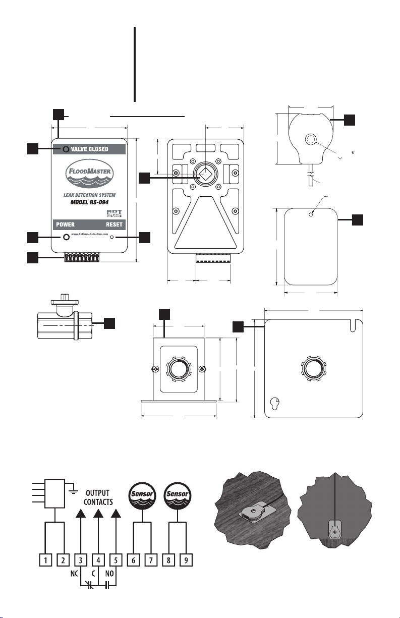
3. The receiver connector comes prewired with basic connections to the power supply and the sensor.
Using an appropriate screwdriver, make any additional electrical connections as may be desired for
output contacts or additional sensors per wiring Figure 1. (Note: additional sensors can be connected
to either 6 & 7 or 8 & 9, as wiring space allows.) Then snap the terminal wiring block into the receiver
housing at the mating slot provided.
4. Secure the valve body in one hand and snap the receiver into place on the valve body mounting pad.
(Note: Improper alignment of the valve stem may interfere with proper receiver mounting. If any resistance
is encountered, conrm the witness mark on the valve stem is in alignment with the valve ports. Use an
appropriate hand tool, such as pliers, to clamp down on the valve stem and turn in the appropriate direction
until the desired position is achieved).
5. Place the sensor(s) where water is most likely to rst accumulate (such as the drain pan or the oor next
to the tank). The sensor is magnetic and can be installed horizontally or vertically in conjunction with the
metal plate – see Figure 2.
• Clean the desired location area to ensure the surface is clean for optimum plate adhesion.
• Peel the backing off the metal plate to reveal the adhesive and stick in place.
•
Place the sensor on the plate as close as possible to the oor, allowing the magnets to secure it in place.
Note: The sensor features a through-hole that can be used to screw it onto a surface if a more permanent
installation is desired or necessary.
6. Turn off the main power. Wire the appropriate inputs to the main power source. Wire the blue and yellow
wires (24V AC output) to the plenum wire that is prewired to the power input of the contact plug. Turn on
the main power. The green “Power” indicator light on the receiver will turn on.
7. Function Test the system as follows:
• Place the sensor on a wet paper towel. The audible alarm will sound and the valve will rotate to the
closed position.
• The red “Valve Closed” LED will turn on when the valve is completely closed (approximately 45-second
cycle time). Open a hot water faucet and conrm that there is no water ow.
• Remove the sensor from the paper towel, dry the contact points, and place it back in the desired
location on the metal plate.
• Press and release the “Reset” button on the receiver to open the valve and begin the ow of water
again (approximately 45 seconds to fully re-open). The green “Power” indicator light will ash once to
indicate the reset process has begun. Open a hot water faucet and inspect for water ow.
TRANSFORMER WIRING INSTRUCTIONS
The supplied transformer has multiple input taps to accommodate different line voltages. If the existing line
voltage you have at your facility is:
120V AC – The WHITE wire from the transformer should be connected to the hot leg of the input voltage
and the black wire to the neutral leg.
208V AC – The RED wire from the transformer should be connected to the hot leg of the input voltage and
the black wire to the neutral leg.
240V AC – The ORG wire from the transformer should be connected to the hot leg of the input voltage and
the black wire to the neutral leg.
The GREEN wire in all cases must be connected to EARTH GROUND.
Each wiring combination as stated above yields the same 24V AC output across the BLUE and YELLOW wires
of the secondary winding of the transformer. See back for Transformer Mounting Instructions.

RS-094-MK6
WATER
HEATER KIT
1. Receiver box
2. Valve Closed LED
3. Power LED
4. Wiring terminal block
5. Reset button
6. Valve actuator
7. Water sensor
8. Metal plate
9. Shut-off valve
10. Step-down transformer
11. Transformer mounting plate
4
3 5
3.0
3.1
1.53.0
1.4
2.5
.4
1.4
1.11.350
4.9
1FRONT VIEW BACK VIEW
2
6
2.56
Ø .12 THRU
1.77
.02
1.48
1.69
8 FT LEAD
.30
.04
PIN OFFSET
FROM SURFACE
Ø .25 .30
Ø .38 x 82°
7
8
9
See technical data submittal
sheet for valve dimensions.
WHITE
RED
BLACK
Sensor leads not polarized.
TRANS-
FORMER
MAIN POWER IN
24 VAC OUT
120
VAC WHT GRN
208
VAC RED
240
VAC ORG
C
OM BLK
BLUYEL
BLK RED
FIGURE 1 –
WIRING DIAGRAM
FIGURE 2 –
SENSOR INSTALLATION OPTIONS
HORIZONTAL VERTICAL
2.200
2.770
2.700
3.250
4.250
4.250
10
11

All specications subject to change without notice.
© Copyright 2020 Reliance Detection Technologies, LLC – A Madison Company
ECN # 11386, 07/2020, MF108, RevB
TRANSFORMER MOUNTING INSTRUCTIONS
The kit contains a cover plate for a standard junction box. The cover has a hole or knock out in the center. It
is designed such that the transformer can be mounted to it and then screwed into the junction box.
1. To mount the transformer to the cover, carefully route its primary wires through the hole in the cover.
2. Tilt the cover so that the head of the retaining screw on the transformer is over the cover.
3. Back the screw out until the cover slips under the threaded end of the retaining screw.
4. Tighten the screw until the transformer is secured on the cover. The threaded end of the screw is designed
to press against the cover to hold the transformer in place.
OUTPUT SIGNAL CONNECTIONS
The unit also provides output signal capabilities (SPDT Relay Output Contact) for connection to a home
security panel or for use with an appropriate relay to control a secondary device, such as a pump. See
Figure 1 for wiring diagram.
Normally Closed Circuit – Terminal Pins 3 & 4 Normally Open Circuit – Terminal Pins 4 & 5
OPERATION & SYSTEM RESET
In the event the system activates, locate the source of the leak, remove the sensor from the water and
dry the metal contacts on the bottom. Correct the problem causing the leak and replace the sensor in the
desired leak detection location once again as required. Press and release the “Reset” button on the receiver
to open the valve and begin the ow of water again. The green “Power” indicator light on the receiver will
ash once to conrm the reset.
MAINTENANCE
Test the system annually per the function test (install step 7) to ensure correct operation and maintain product
warranty status. At a minimum, exercise (press and release) the “Reset” button on the receiver annually.
EMERGENCY MANUAL VALVE OPERATION
The unit is equipped with an emergency feature for the manual rotation of the valve. Disengage the actuator
from the valve and manually changing the valve to open or closed as follows:
1. Turn off the main power to the transformer.
2. Stabilize the water feed line by grabbing it in one hand near the valve. While grasping the actuator
housing in the other hand, pull the actuator housing away from the water feed line.
3.
Using an appropriate hand tool (such as a pliers), clamp down on valve stem and turn in the appropriate
direction until the desired position is achieved. Note the top of the stem is slotted to indicate valve position
(in line with water ow would indicate open valve; slot across water line would indicate closed valve).
4. Before remounting the actuator, return the valve to the original position prior to the manual rotation.
5. Remount the actuator and restore the main power to the transformer.
6. Test for correct operation per the function test listed in install step 7.
203-488-2684 or 888-771-4929
27 Business Park Drive, Branford, CT 06405
www.RelianceDetection.com [email protected]
NEED INSTALLATION OR SETUP ASSISTANCE?
Call toll-free: 888-771-4929 or visit www.RelianceDetection.com/support/RS-094
Table of contents