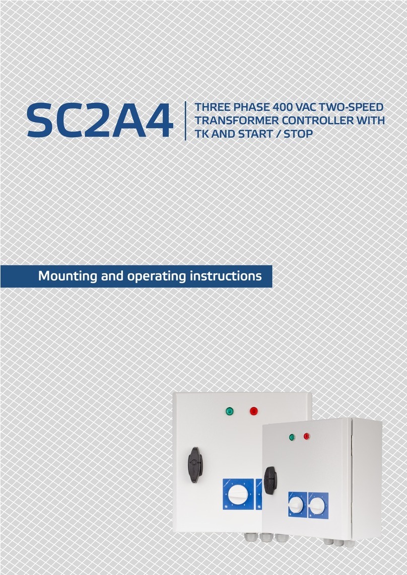
Sentera Controls ECH-8-DM Service manual

ECH-8-DM CONTROLLER FOR WATER
HEATERS / COOLERS WITH
EC FAN
Mounting and operating instructions

www.sentera.eu
MIW-ECH-8-DM-EN-000-22/08/2022 2 - 10
back to the table of contents
ECH-8-DM CONTROLLER FOR WATER
HEATERS / COOLERS WITH EC FAN
Table of contents
SAFETY AND PRECAUTIONS 3
PRODUCT DESCRIPTION 4
ARTICLE CODES 4
INTENDED AREA OF USE 4
TECHNICAL DATA 4
STANDARDS 4
OPERATIONAL DIAGRAMS 5
WIRING AND CONNECTIONS 6
MOUNTING INSTRUCTIONS IN STEPS 6
OPERATING INSTRUCTIONS 8
VERIFICATION OF INSTALLATION 9
TRANSPORT AND STORAGE 10
WARRANTY AND RESTRICTIONS 10
MAINTENANCE 10

www.sentera.eu
MIW-ECH-8-DM-EN-000-22/08/2022 3 - 10
back to the table of contents
ECH-8-DM CONTROLLER FOR WATER
HEATERS / COOLERS WITH EC FAN
SAFETY AND PRECAUTIONS
Read all the information, the datasheet, Modbus map, mounting and operating
instructions and study the wiring and connection diagram before working with the
product. For personal and equipment safety, and for optimum product performance,
make sure you entirely understand the contents before installing, using or maintaining
this product.
For safety and licensing (CE) reasons, unauthorised conversion and/ or modifications
of the product are inadmissible.
e product should not be exposed to abnormal conditions, such as extreme
temperatures, direct sunlight or vibrations. Long-term exposure to chemical
vapours in high concentration can affect the product performance. Make sure the
work environment is as dry as possible; avoid condensation.
All installations shall comply with local health and safety regulations and local
electrical standards and approved codes. is product can only be installed by
an engineer or a technician who has expert knowledge of the product and safety
precautions.
Avoid contacts with energised electrical parts. Always disconnect the power
supply before connecting, servicing or repairing the product.
Always verify that you apply appropriate power supply to the product and use
appropriate wire size and characteristics. Make sure that all the screws and nuts
are well tightened and fuses (if any) are fitted well.
Recycling of equipment and packaging should be taken into consideration and these
should be disposed of in accordance with local and national legislation/regulations.
In case there are any questions that are not answered, please contact your
technical support or consult a professional.

www.sentera.eu
MIW-ECH-8-DM-EN-000-22/08/2022 4 - 10
back to the table of contents
ECH-8-DM CONTROLLER FOR WATER
HEATERS / COOLERS WITH EC FAN
PRODUCT DESCRIPTION
e ECH series are controllers for water air coolers or hot water air heaters that
are equipped with EC fans. Typically, they are used to cool or to heat warehouses
and industrial areas. e temperature setpoint can be steplessly adjusted via the
potentiometer. It has an unregulated output (ON-OFF) to control a water valve or
electric heater. e EC fan speed can be manually selected via the rotary switch
with 7 positions (Automatic, 5 manual steps and OFF). In Automatic mode, EC fan
speed is regulated automatically based on the setpoint temperature. All settings can
be adjusted via Modbus RTU communication. In remote mode, the controller can be
overdriven by remote Master device.
ARTICLE CODES
Article code Supply voltage
ECH-8-DM 85 – 305 VAC / 50 – 60 Hz
INTENDED AREA OF USE
■Warehouse air coolers equipped with EC fan and water valve
■e ideal controller for hot water air heaters in warehouses, sheds/stables, etc.
■Temperature controlled ventilation systems
■For indoor use, surface wall mounted
TECHNICAL DATA
■Supply voltage: 85 - 305 VAC / 50 – 60 Hz
■Stepless analogue output in automatic mode: 0 – 6 (0 – 10) VDC / max. load 200 Ω
■Relay output for valve / heater control: supply voltage (Us) / Imax 10 A
■Heating/cooling mode with jumper setting
■Analogue output with jumper (0-6 / 0- 10 VDC) or Modbus setting
■Input for PT500 temperature sensor
■Control switch with 7 positions: Off position + hand set position 1 to 5 + Auto
mode
■Potentiometer for temperature setpoint (range: 5°C – 35°C)
■RGB LED for status indication
■Modbus RTU communication
■Plastic enclosure for wall fixing
■Protection class: IP54
■Operating ambient conditions:
►Temperature: -10—50 °C
►Rel. humidity: 5 – 90% rH, non-condensing
STANDARDS
■Low Voltage Directive 2014/35/EU
■Electromagnetic Compatibility (EMC) Directive 2014/30/EU
■RoHS Directive 2011/65/EU

www.sentera.eu
MIW-ECH-8-DM-EN-000-22/08/2022 5 - 10
back to the table of contents
ECH-8-DM CONTROLLER FOR WATER
HEATERS / COOLERS WITH EC FAN
OPERATIONAL DIAGRAMS
Auto mode - heating
Unregulated output - water valve or heater control Analogue output - EC fan speed control
35 ° C 5 ° C
0,4 ° C
Valve / heater
output
Setpoint
Temperature
Ts [°C]
Measured
temperature
T [°C]
Us (230 VAC)
0 VAC
0
20
40
60
80
100
35 ° C 2 ° C 5 ° C
0,4 ° C
Analogue
output [%]
Setpoint
Temperature
Ts [°C]
Measured
temperature
T [°C]
Auto mode - cooling
Unregulated output - water valve control Analogue output - EC fan speed control
5 ° C 35 ° C
0,4 ° C
Valve
output
Setpoint
Temperature
Ts [°C]
Measured
temperature
T [°C]
Us (230 VAC)
0 VAC
Analogue
output [%]
Setpoint
Temperature
Ts [°C]
Measured
temperature
T [°C]
0
20
40
60
80
100
35 ° C 2 ° C 5 ° C
0.4
Manual mode
0 1 2 3 4 5
0
20
40
60
80
100
Analogue
output [%]
Switch position
Heating Cooling
T > Ts
Valve / heater output: 0 VAC
EC fan speed: minimum value
Valve / heater output: 230 VAC
EC fan speed: Acc. rotary
switch position
T < Ts
Valve / heater output: 230 VAC
EC fan speed: Acc. rotary
switch position
Valve / heater output: 0 VAC
EC fan speed: minimum value
T – measured temperature
Ts – temperature setpoint

www.sentera.eu
MIW-ECH-8-DM-EN-000-22/08/2022 6 - 10
back to the table of contents
ECH-8-DM CONTROLLER FOR WATER
HEATERS / COOLERS WITH EC FAN
WIRING AND CONNECTIONS
L, N, PE Supply voltage 85 – 305 VAC / 50 – 60 Hz
PE, N, L1 Unregulated output to control an external water valve or electric
heater - Imax 10 A
TEMP Optional temperature sensor PT500 (type FLTSN-P500-010 or
similar)
Ao, Gnd Analogue output to control EC fan speed (0 - 6 VDC or 0 - 10 VDC)
A, /B Modbus RTU communication
ATTENTION Make sure you use cables with an appropriate diameter to connect the fans to
the ECH controller.
MOUNTING INSTRUCTIONS IN STEPS
Before you start mounting the unit, read carefully “Safety and Precautions” and follow
these steps:
1. Unscrew the front cover and open the enclosure.
2. Fix the unit onto the wall or panel using the provided screws and dowels. Mind
the correct position and mounting dimensions as shown in Fig. 1 and Fig. 2.
Fig. 1 Mounting dimensions Fig. 2 Mounting position
128,5
180
208
92,5
98
115
Correct Incorrect
6
TEMP.
5°
20°
30°
35°
10°
25°15°
6
TEMP.
5°
20°
30°
35°
10°
25°15°
3. Insert the cables through the cable glands and do the wiring according to the
wiring diagram (see Fig. 3) while adhering to the information from section
“Wiring and connections” above.
3.1 Connect the power supply cables to the terminals.
3.2 Connect the cables of the load (fans and valve/heater) to the terminals.
3.3 Connect the power earth cables to the dedicated places.
3.4 Install the temperature probe in such a way it measures the temperature in
the air of the desired area.
Cables must be less than 4m.

www.sentera.eu
MIW-ECH-8-DM-EN-000-22/08/2022 7 - 10
back to the table of contents
ECH-8-DM CONTROLLER FOR WATER
HEATERS / COOLERS WITH EC FAN
Fig. 3 Wiring and connections
24
3
11
1 - Terminal
block
LNPE PE NL1
TEMP Ao GND A/B
Supply voltage
(Us)
Unregulated
output
LNPE PE NL1
TEMP Ao GND A/B
Temperature
sensor PT500
Analogue output
Modbus RTU
communication
2 - Analogue
output range
selection
Jumper removed (default) - 0-6 VDC
Jumper installed - 0-10 VDC
3 - Temperature
mode
selection
Jumper removed (default) - heating
Jumper installed - cooling
4 - PROG header 12345
Put a jumper onto pins 1 and 2 and wait
for at least 5 seconds to reset the Modbus
communication parameters
12345
Put a jumper onto pins 3 and 4 and restart the
supply to enter bootloader mode
4. Tighten the cable glands.
5. Close the cover and secure it with the screws.
ATTENTION A safety isolator / disconnect switch should be installed on the mains electricity
side of all motor drives.

www.sentera.eu
MIW-ECH-8-DM-EN-000-22/08/2022 8 - 10
back to the table of contents
ECH-8-DM CONTROLLER FOR WATER
HEATERS / COOLERS WITH EC FAN
OPERATING INSTRUCTIONS
ATTENTION Make sure the connections are correct before you power the unit.
ATTENTION Make sure the mains supply voltage is within the admissible rated maximum
current of the product.
ATTENTION Several fans can be connected in parallel to the controller as long as the maximum
total current of all fans does not exceed the current rating of the controller.
1. Plug the ECH into the mains electricity network.
2. Select the requested temperature via the left rotary switch (Fig. 4).
Fig. 4 Temperature setpoint selection
35 °C
5 °C
20 °C
0
1
234
5
A
35 °C
5 °C
20 °C
0
1
234
5
A
3. Select the operating mode by turning the control switch / knob on the right to
the relevant position.
3.1 Manual mode
In manual mode, the fan speed can be selected manually via the switch
(position 1 - 5) (Fig. 5). In heating mode, the motor will be enabled at
the selected speed if the measured temperature is lower than the set
temperature. Once the measured temperature exceeds the set temperature,
the motor will be disabled. In cooling mode, the motor will be enabled as
long as the measured temperature is higher than the set temperature. e
unregulated output is activated (230 VAC) while the motor is enabled.
Fig. 5 Manual mode
35 °C
5 °C
20 °C
0
1
234
5
A
35 °C
5 °C
20 °C
0
1
234
5
A

www.sentera.eu
MIW-ECH-8-DM-EN-000-22/08/2022 9 - 10
back to the table of contents
ECH-8-DM CONTROLLER FOR WATER
HEATERS / COOLERS WITH EC FAN
3.2 Automatic mode
When Auto mode has been selected, the controller changes the five speeds
automatically according to the setpoint temperature selected via the
temperature potentiometer (Fig. 6).
Fig. 6 Automatic mode
35 °C
5 °C
20 °C
0
1
234
5
A
35 °C
5 °C
20 °C
0
1
234
5
A
3.3 Remote mode
Remote mode turns off all user interfaces except Modbus RTU
communication. After the remote mode is selected (holding register 20),
LED, analogue and unregulated output states are controlled by a Modbus
master device via holding registers 21-24.
If the Modbus safety timeout register (Holding register 8) is not 0, it means
the Modbus safety timeout is set. erefore, when the time runs out due to
no Modbus communication, the analogue output value will be “position 1”
value (holding register 12). After Modbus communication is recovered, the
analogue output value will follow again the sensor settings.
VERIFICATION OF INSTALLATION
ATTENTION Use only tools and equipment with non-conducting handles when working on
electrical devices.
Safe operation depends on proper installation. Before start up, ensure the following:
■e mains supply is connected correctly.
■e speed regulator must be properly earth protected.
■During operation, the unit must be closed.
■Protection is provided against electrical shocks.
■e cables are the appropriate size and fuse-protected.
■ere is sufficient air flow around the unit.
Vericationofoperation:
■Switch ON the mains supply.
■Set the temperature to the minimum position (5 °C).
■e connected fan must stop – (if the ambient temperature is higher than the
selected setpoint value).
■e valve/heater must be closed.
■Set the temperature setpoint to the maximum position (35 °C).
■e connected fans must run at max speed (6 VDC) – (if the measured temperature
is below the setpoint value).
■e valve/heater must be open (230 VAC).
If the unit does not work according to the instructions, the wiring connections and
settings need to be checked.
www.sentera.eu
MIW-ECH-8-DM-EN-000-22/08/2022 10 - 10
back to the table of contents
ECH-8-DM CONTROLLER FOR WATER
HEATERS / COOLERS WITH EC FAN
ATTENTION Applying overvoltage to any of the logical controller parts will cause improper
operation or failure to the internal circuit.
ATTENTION Disconnect and confirm that there is no live current flowing to the unit before servicing.
ATTENTION Avoid exposing the controller to direct sunlight!
TRANSPORT AND STORAGE
Avoid shocks and extreme conditions; stock in original packing.
WARRANTY AND RESTRICTIONS
Two years from the delivery date against defects in manufacturing. Any modifications
or alterations to the product after the date of publication relieve the manufacturer
of any responsibilities. e manufacturer bears no responsibility for any misprints or
mistakes in this data.
MAINTENANCE
In normal conditions this product is maintenance-free. If soiled, clean with a dry or
damp cloth. In case of heavy pollution, clean with a non-aggressive product. In these
circumstances the unit should be disconnected from the supply. Pay attention that
no fluids enter the unit. Only reconnect it to the supply when it is completelydry.
Table of contents
Other Sentera Controls Water Heater Accessories manuals