Norma Icon-5 Operating manual
1
TDMG0002 Icon-5 Maintenance Guide –Version: 02 –Release date: 2020-04-27
Icon-5 Maintenance Guide
Kit description and procedures
This document describes the contents of the maintenance kit and list the corresponding
maintenance procedures for Norma Icon-5 automated hematology analyzer.
Special tool required: UNF tool (not included in the kit)
Please contact our support team at support@normadiagnostika.com if further information or
clarification is required.
Icon-5 Maintenance Kit (HAT827A) –for 1-year/10.000 sample period
Item
Part#
pcs
Aperture maintenance kit
HAT809A
1
Peristaltic pump tube set for “gray” and “orange”
pumps
HAT800B
HAT800C
1 pair of each
Lubricants (in small containers)
-Shell Retinax lubricant (red)
HAT829A
1
-Teflon based grease (white)
HAT829B
1
-Silicone grease (clear)
HAT829C
1
Piercing needle with UNF screw and “O” ring
HAT165A
1
Greiner BIO Vacutainer NO add w/o rubber in cap
(White)
HAT823B
1
2
TDMG0002 Icon-5 Maintenance Guide –Version: 02 –Release date: 2020-04-27
Maintenance procedure on Icon-5 analyzers
These steps must be performed by trained service engineer! Please note the following
warnings:
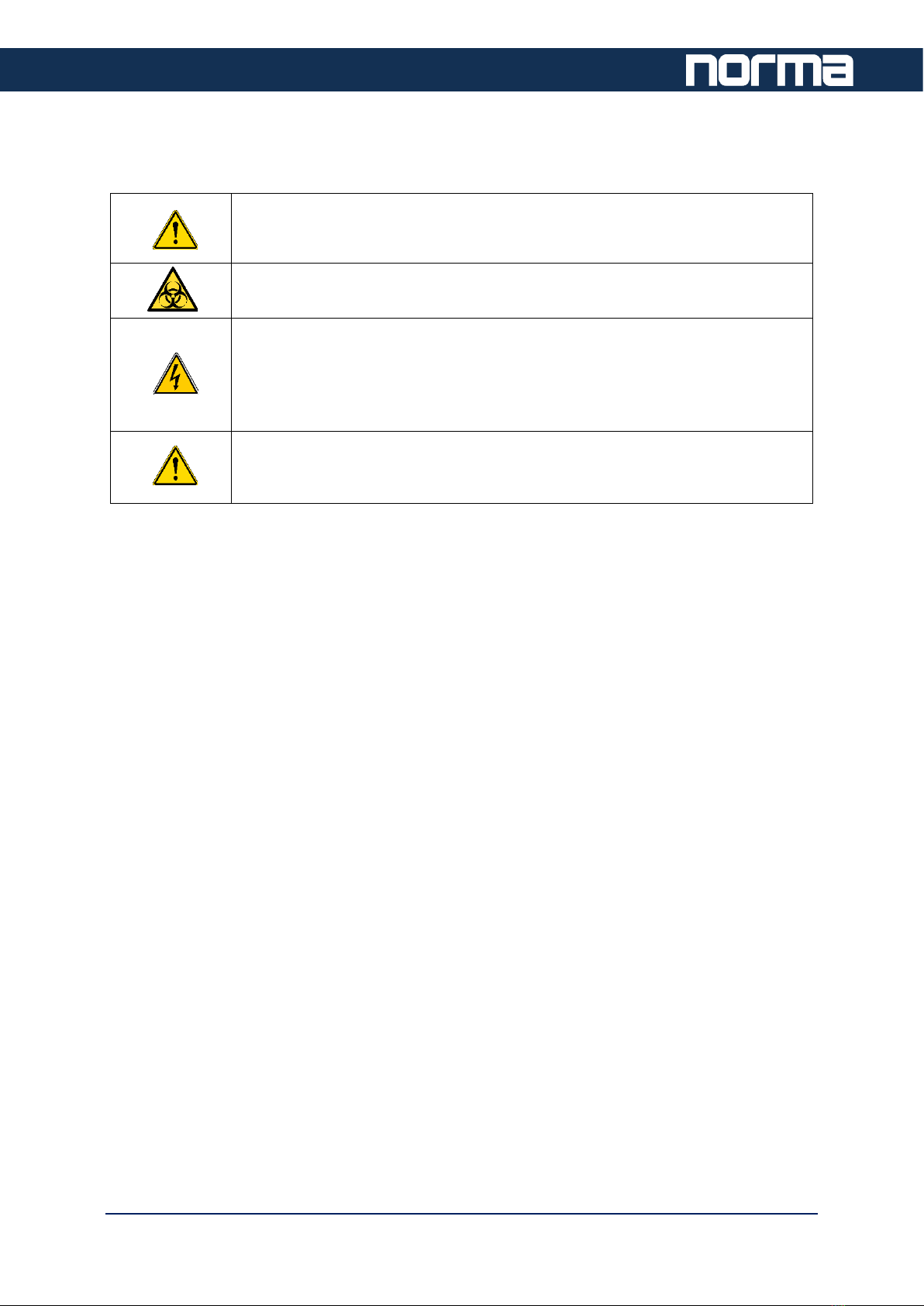
WARNING
Risk of personal injury. Movements of motors are controlled by limited
current. Do not override built-in safety measures, do not short circuit fuses
BIOHAZARD
Risk of biological infection, contamination
WARNING
The analyzer should only be operated without covers with extreme
caution, moving parts can cause injury. High Voltage board HVDCDC
produces 180VDC.
Service marked components only when the power source is disconnected.
WARNING
Risk of personal injury. The ceramic shear valve has a sharp needle
installed. Avoid touching the needle
To prepare the Icon-5 for the maintenance, please, shut down the analyzer and pinch
the reagent pickup tubes using the clamps provided in the reagent pickup tube set,
and remove both side covers to get easy access to the inner components.
3
TDMG0002 Icon-5 Maintenance Guide –Version: 02 –Release date: 2020-04-27
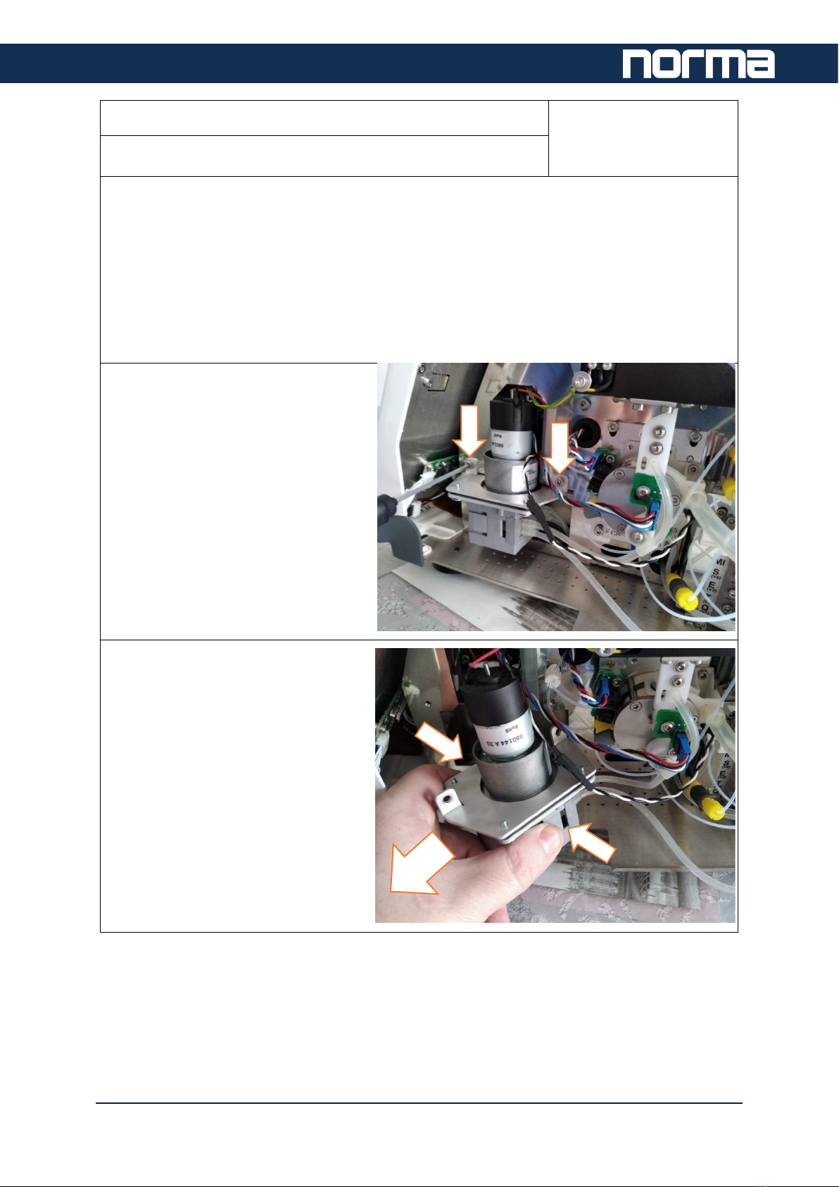
Step 1: Peristaltic pump tube replacement
Frequency:
1 year or 10,000
samples
part#: HAT800B or HAT800C (Included in kit)
Pump tubes must be replaced regularly. The tube material will wear with time and use of
the analyzer.
Failure to replace the tubes will results in deepening cracks on the tube material which will
eventually lead to leaks and reduction or failure in liquid movement.
The wash head will slowly fail to remove waste from the sampling needle washing
procedure. RBC sample processing errors (variation, instability of results) and in extreme
cases waste collector overflow may be the consequences.
Remove the pump module (open the
two screws fixing the module to the
assembly plate)
Remove the pump cassette by
pressing it on its sides and then
pulling it away from the pump.
4
TDMG0002 Icon-5 Maintenance Guide –Version: 02 –Release date: 2020-04-27
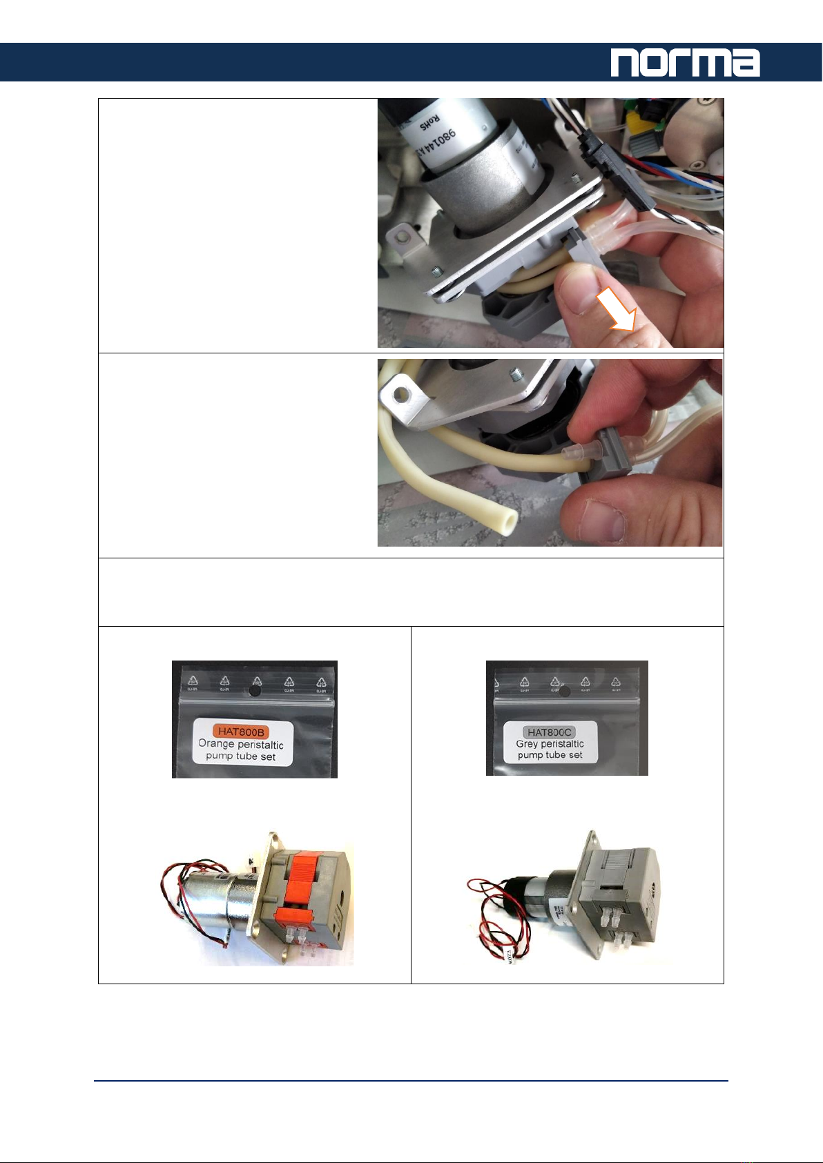
Remove the pump tubes (gently pull
on the adapter to release it from the
groove)
Pull the tubes off the tube adapters.
The kit contains two different sets of pump tubes.
Different tubes must be used for different pumps.
HAT800B
Use it for the pump with ORANGE cassette
HAT800C
Use it for the pump with GREY cassette
5
TDMG0002 Icon-5 Maintenance Guide –Version: 02 –Release date: 2020-04-27
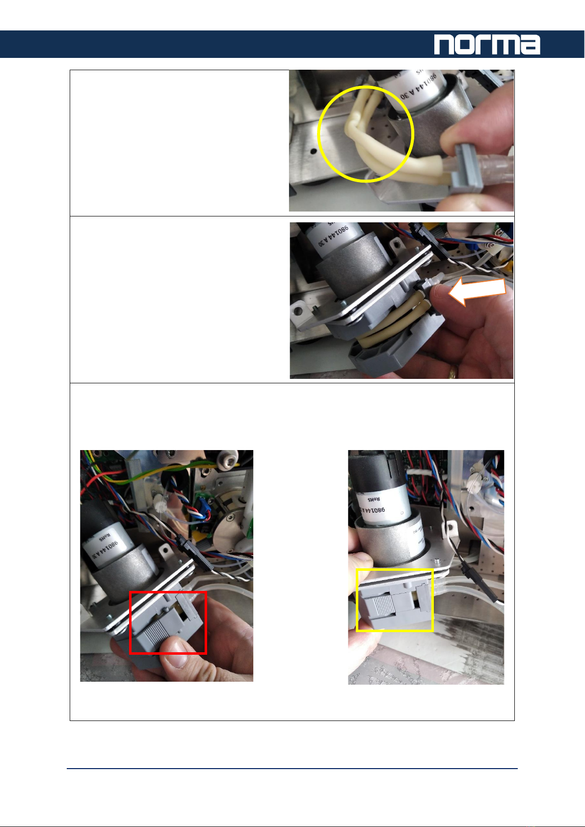
Install tubes, make sure they run parallelly,
they must not cross each other.
Reinstall the pump tubes. The adapter
heads will sit in the grooves at the pump
body. Slightly pull on the tubes to make
them sit properly in the pump over the
rollers.
Reinstall the cassette. Both ends must CLICK upon insertion. Make sure that the cassette
is level with the pump body. Incorrect alignment of the cassette will not allow the pump to
operate properly, it will fail to move liquid. If the cassette shows only a little gap, simply
push on the top of the cassette to push it in place.
Wrong cassette installation Good cassette alignment
Other Norma Medical Equipment manuals


Popular Medical Equipment manuals by other brands


Getinge
Getinge Arjohuntleigh Nimbus 3 Professional Instructions for use

Mettler Electronics
Mettler Electronics Sonicator 730 Maintenance manual

Pressalit Care
Pressalit Care R1100 Mounting instruction

Denas MS
Denas MS DENAS-T operating manual

bort medical
bort medical ActiveColor quick guide

AccuVein
AccuVein AV400 user manual


