NORSELIGHT XENON R50 Series User manual

Glamox Production GmbH & Co. KG
Glasower Weg 5, 17166 Teterow, Germany Doc.: 7SL2002001; Rev: 04
www.glamox.com/gmo DCN: 22880
Date: 2019-11-07
USER’S MANUAL
SEARCHLIGHTS XENON R50

2
This manual belongs to the product
Serie no.: ______________
Controlled by: ______________
Date: ______________
Technical Manual
for Xenon searchlight
XS 500 R50
XS 1000 R50
XS 1600 R50
XS 2000 R50
XS 3000 R50
1 x 230 VAC
1 x 115 VAC

3
For more than 90 years, Norselight have designed and manufactured lighting products for marine
vessels. Through ongoing customer focused product development, Norselight continue to deliver
quality products as demanded both at sea and on the rugged coastlines as the Norwegian.
This commitment to quality and expertise provides the foundation for Norselight to be possibly the
world’s leading supplier of maritime lighting.
However, in order to stay in front, Norselight would very much appreciate all comments that you
may have regarding our quality products or services.
Therefore, if you have any technical or other questions, our Technical Department can be contacted
as follows:
Glamox Production GmbH & Co. KG
Glasower Weg 5, 17166 Teterow, Germany
www.glamox.com/gmo
We would also like to use this opportunity to thank you for choosing Norselight as your supplier of
marine searchlights.
The guarantee is only valid against production faults. It do not cover damage caused by
transportation, damage due to disregard of this technical Manual or adverse external effects.
Guarantee regarding the bulb, please look at the guarantee papers following the bulb. This must be
filled in and returned to Norselight.
Norselight is a registered trade name.
Norselight reserves all rights to this document.
Norselight operates a policy of continuous development. On this basis we reserve the right to make
changes and improvements to all of our products and documentation.
Introduction
Guarantee

4
Table of contents
Introduction..........................................................................................................................................3
Guaranty...............................................................................................................................................3
1 General description........................................................................................................................5
1.1 Searchlight..............................................................................................................................5
1.2 The motor housing..................................................................................................................5
1.3 Control panel...........................................................................................................................5
1.4 The Ethernet Switch: ..............................................................................................................8
1.5 High Sensitive Receiver: ........................................................................................................8
1.6 Main Control Panel position indicator versus searchlight position:.....................................10
1.7 Power Supply (Rectifiers):....................................................................................................11
2 Technical data..............................................................................................................................16
2.1 Xenon Searchlight.................................................................................................................16
2.2 Main Operation Panel...........................................................................................................17
2.3 Slave Operation Panel...........................................................................................................17
2.4 Wireless Operation Panel......................................................................................................18
2.5 Switch ...................................................................................................................................19
2.6 Access Point..........................................................................................................................20
3 Installation...................................................................................................................................21
3.1 Mechanical installation.........................................................................................................21
3.2 Electric installation...............................................................................................................21
3.3 BUS installation....................................................................................................................22
3.4 Start up procedure.................................................................................................................22
4 Operation.....................................................................................................................................23
4.1 Operation Panels function.....................................................................................................23
4.2 Change of the lamp...............................................................................................................24
4.3 General Searchlight Maintenance.........................................................................................24
5 Spare Parts list.............................................................................................................................25
6 Drawings......................................................................................................................................27
6.1 Mechanical Dimensions........................................................................................................27
6.2 Ethernet BUS........................................................................................................................36
6.3 Electrical...............................................................................................................................39
6.4 Internal Wire Diagram..........................................................................................................46

5
The searchlights XS 500-1000-1600-2000 and XS 3000 are made from seawater resistant aluminium, welded and
finished with white powder coat. The lamp housing basically contains one a lamp, a glass-reflector covered with
silver, noise filters and a focus-motor for adjustment of the light beam.
The R50 motor housing is made from seawater resistant aluminium and finished with white powder coat. The motor
housing basically contains one motor for vertical and another one for horizontal movement, a thermostat driven
heating element and the electronic control system.
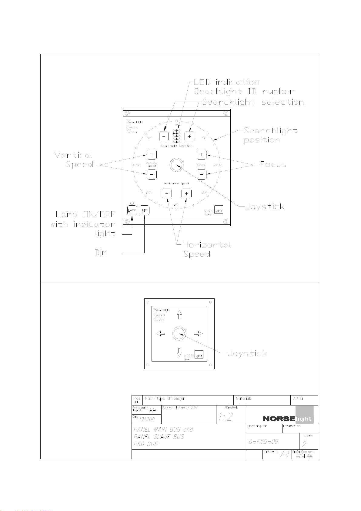
Main Operation Panel.
It contains the following functions:
•Ready for max. 2 Slave Operation Panels (option)
•BUS communication.
•Lamp ON/OFF
•Joystick for sweep and tilt, horizontal and vertical movement.
•Speed regulator for sweep and tilt.
•Focus +/- (light beam adjustment)
•LED Indication for searchlight position 360o.
•Searchlight ID-number
•End position function
•Designed for console or bulkhead mounting from front.
•DIM LED intensity on Main Operation Panel
Slave Operation Panel (Option).
It contains:
•Joystick
•Designed for console or bulkhead mounting from front.
Wireless Operation Panel (Option).
It contains:
•On/Off Button
•Lamp ON/OFF
•Touch buttons for sweep and tilt, horizontal and vertical movement.
•Speed regulator for sweep and tilt.
•Focus +/- (light beam adjustment)
•LED Indication for searchlight position 360o.
•Searchlight ID-number
•End position function
•Battery charger
1General description
1.1 Searchlight
1.2 The motor housing
1.3 Control panel
6
Main and Slave Operation Panel

7
Wireless Operation Panel

8
It contains:
•5 port x RJ45
•DIN rail mounting
•Power 24V DC + ground
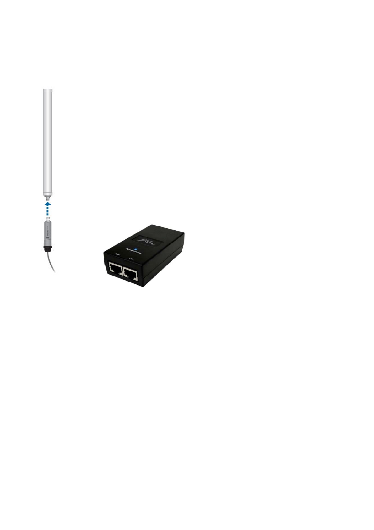
The Access Point is a high sensitive receiver for the wireless panel build for maximum range and durability. The
Access Point communicate with the wireless bus, witch remotely controls the searchlights with R50 motor unit. The
control system is based on TCP/IP technology were several different Operator Panel can control separately up to 9
searchlights of Xenon or Halogen. The system is connected to the same network through LAN switch to connect to
a network of searchlights. Control panels both hard wired and wireless, are fitted into a standard solution.
1.4 The Ethernet Switch:
1.5 High Sensitive Receiver:
9
Features and Benefits:
•Wireless receiver for SCS wireless Bus
•Bolt-on to Norselight`s network of searchlights
•Weatherproof Aluminium Casing, Compact and new design
•Based on TCP/IP technology
•Waterproof, quick disconnect RJ-45 connector
•Custom made for Offshore
•Supports masts from 1 to 2" diameter
•200m Area wireless coverage
•IP66,RoHs, FCC, CE, IC Complaint
•-40 to +80 degree operation temperature
Package Include:
•1x Wireless receiver unit
•1x PoE Power supply
•1x 8dBi wireless antenna
•(Network cables, not included)

10
In accordance to MSC/Circ. 982 Pos 5.5.1 “Movement of Controllers” and 5.5.2 “Corresponding Movements “
The position indicator on the Main Control Panel indicates the position of the searchlight. 0oposition on the panel
indicates that the searchlight is positioned straight forward compared to the searchlight 0oposition.
The searchlight has an 180omovement to the left and right end position, in total 360o.
To calibrate the position indicator, you simply use the joystick on the Main Control Panel to turn the searchlight to
end stop to both left and right end position.
1.6 Main Control Panel position indicator versus searchlight
position:

11
1.7 Power Supply (Rectifiers):

12
EX-30 G/1
EX30-G/1, single phase 90-265V 50/60Hz electronic power supply is specifically suitable for feeding 250 to 500W
short arc Xenon lamps. Weight 8kg. Further instructions in Installation guide for Rectifier.
1. Lamp ON/OFF switch
IMPORTANT NOTE: DO NOT USE THIS SWITCH FOR THE REMOTE
CONNECTION !
2. Mains on LED
3. Lamp current potentiometer
Adjusting the lamp output current
4. Input terminal board
5. Output terminal board
Used to connect the lamp power cables (+, -)
6. Current LED bar
Indicating the output current level (12A to 30A)
7. Lamp ON terminal board
8. Remote lamp ON/OFF terminal board
9. Igniter insertion terminal board
13
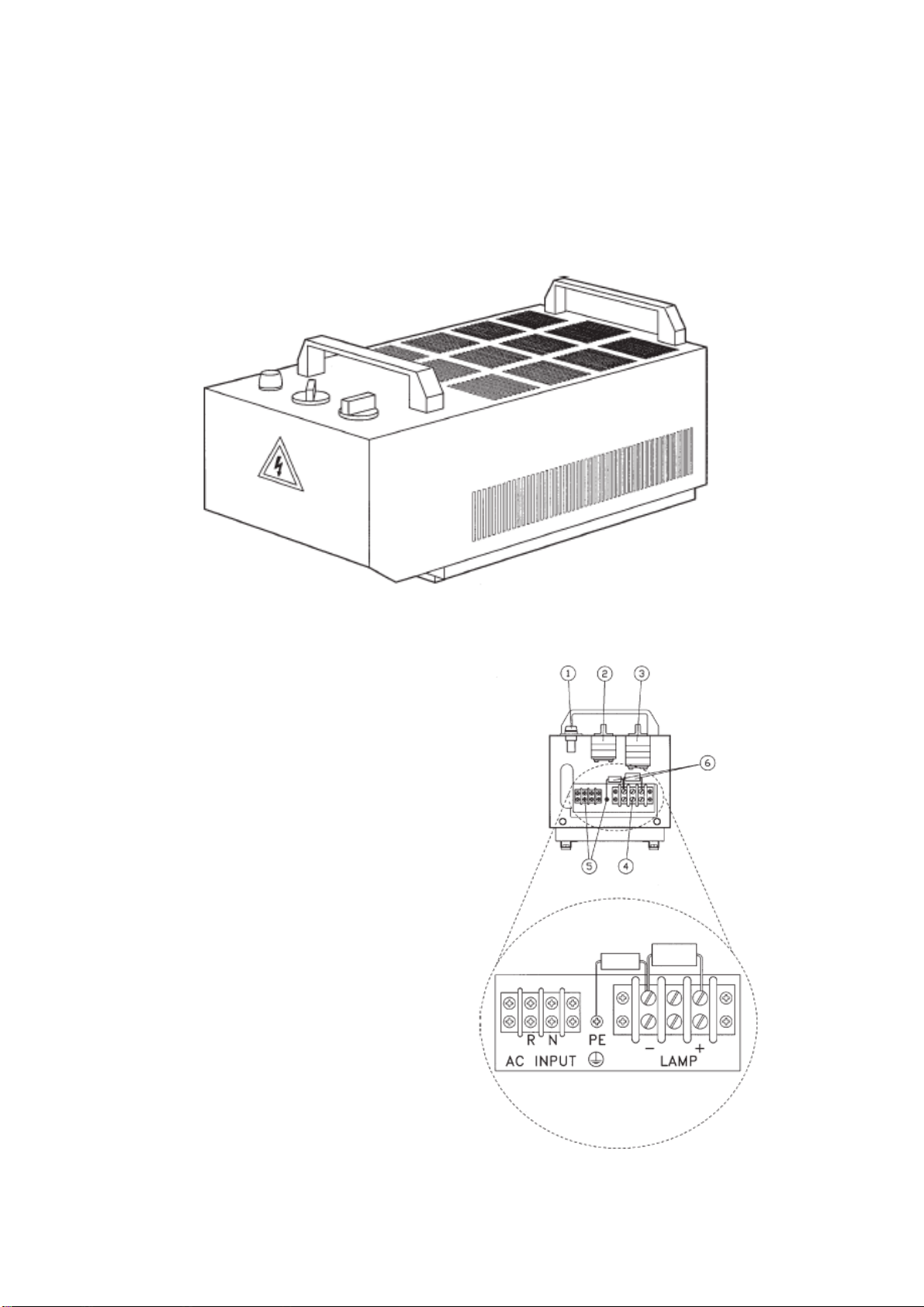
PX-50 N
These extremely compact rectifiers for single-phase inputs have been designed to feed 1000W Xenon lamps,
meeting the requirements of lamps manufacturers to ensure correct operation and long life of the lamp. The units are
fitted with a transformer with taps for output lamp power regulation and a special circuit to avoid the lamp turn off
during the tap switching. The cabinet, equipped with carrying handles, permits an easy inspection of the inside
components. Weight 63 kg. Further instructions in Installation guide for Rectifier.
Control devices
1. Mains fuse (F1)
2. ON/OFF switch and high/low diode protection (C2, C7, C8)
lamp output current setting (Q1)
3. 6 steps lamp output current setting Q2))
4. Output terminals (-,+) (X2)
5. Input terminals (R, N plus PE)(X1)
6. HF filtering capacitors (C5-C6)

14
EX-100 D/1
This electronic power supply for single phase or double phase 230Vac 50/60Hz input, has been designed to feed
from 1000W to 3000W short arc Xenon lamps, meeting all the requirements of lamp manufacturers to ensure
correct operation, long life to the lamp, and high reliability. Weight 18 kg. Further instructions in Installation guide
for Rectifier.
Control devices
1. Synoptic panel
2. Output terminal block
3. Input terminal block
4. RS232 connector
5. Auxiliary connector

15
N3-80 / N3-150
These high quality rectifier power supplies have been expressly designed to ensure the correct operation and long
life of short arc Xenon lamps. These units, developed to meet the recommendations of Xenon lamp manufacturers,
are fitted with special IREM transformers with adjustable magnetic shunt for continuous output regulation over the
entire operating range.
The new and peculiar design guarantees a low acoustical noise, i.e. less than 55dB(A).
The special design, including an auxiliary filter unit, ensures a low ripple with a negligible
starting energy. Weight N3 – 80 101 kg and N3 – 150 154 kg. Further instructions in Installation guide for Rectifier.
Component layout
1) Adjustment hand-wheel
2) Magnetic shunt (MS)
3) Transformers (T1 to T3)
4) Circuit breaker (QF) *
5) Auxiliary contact (S2) *
6) Output filter capacitors (C7 - C8)
7) Auxiliary filter (AF) (L) (on request for N3-
50E, N3-80E, N3-100E models)
8) Protection capacitors (C1 to C6)
9) Ignition relay (A1)
10) Silicon diodes (D1 to D6)
11) Output terminals (+ , -)
12) Ground terminal (PE)
13) Input terminals (U V W)
14) Alarm ON/OFF terminal (X1) *
15) Fuse holder for main switch coil
16) Auxiliary transformer (400V/415V
versions only)
17) Contactor for remote control
18) Auxiliary connector (for manual switch on breaker
connection and fan powering (N3-
150E and N3-180E models))
19) ON/OFF switch with lock
20) Fan (N3-150E and N3-180E models)
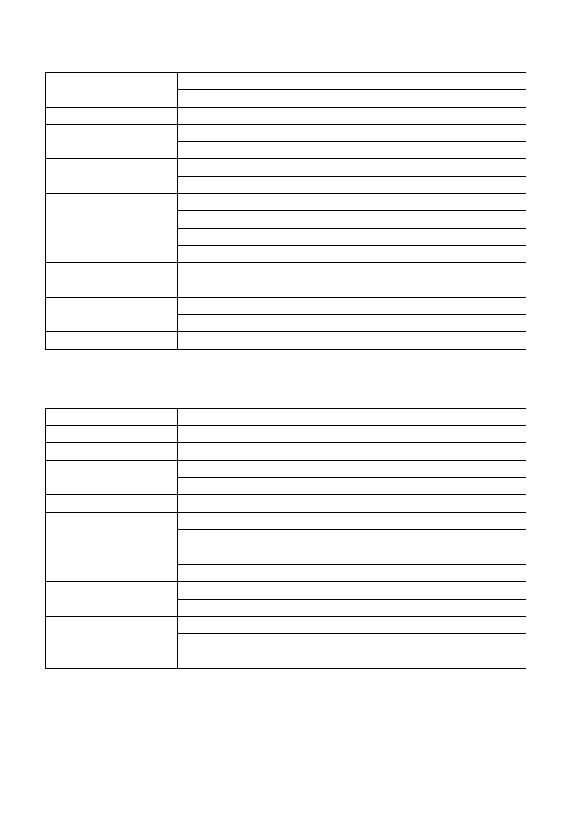
16
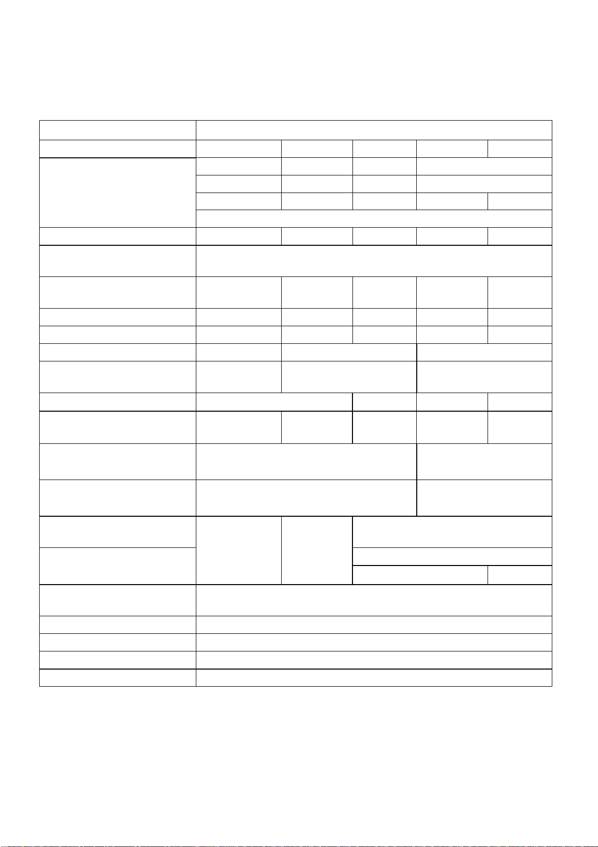
Properties Value
Searchlight XS 500 XS 1000 XS 1600 XS 2000 XS 3000
Dimension Height:
Width:
Weight of searchlight:
Weight of the SCS panel:
890 mm 930 mm 930 mm 1020 mm
470 mm 515 mm 515 mm 615 mm
46,5 kg 49,5 51,5 kg 61,5 kg 64,5 kg
0,5 kg
Lamp type (W) XBO 500 XBO 1000 XBO 1600 XBO 2000 XBO 3000
Working voltage power
supply 115V/230V
Rated Lamp voltage / Rated
lamp current 18V / 28A 20V / 50A 24V / 65A 28V / 70A 29V / 100A
Lifetime (approx.) 2000 h 1500 h 2400 h 2400 h 2200 h
Luminous flux 14 500 lm 32 000 lm 60 000 lm 80 000 lm 130 000 lm
Focus distance 89mm (3,5”) 70mm (2”3/4) 82,6 mm
Parabolic silver plated glass
reflector Dia.305mm
(12”) Dia.356mm (14”) 457 mm ( 18” )
Divergence: 2-7
°
3-8
°
2-7
°
3-8
°
Range at 1 lux:
(Theoretical calculation) 4600m 6400m 7 200 m 9200 m 11500 m
Vertical movement: Speed:
Range: 1-10
°
/sec
+25
°
/ -30
°
2.8
°
/sec
+ -25
°
Horizontal movement: Speed:
Range: 1-20
°
/sec
±
180
°
1-18
°
/sec
±
180
°
Type of Power Supply 115V
EX-30 G/1 ;
NP-0725
PX-50N ;
NP-0725
On request
Type of Power Supply 230V EX-100D/1
N3 -80 N3-150
Drum and motor housing
material Seawater resistant aluminium 57S
Fork and lifting rod material Stainless steel SIS AISI 304
Screw joint material Stainless steel A4
Surface treatment White powder coated (RAL 9016)
Protection class IP 56
2Technical data
2.1 Xenon Searchlight
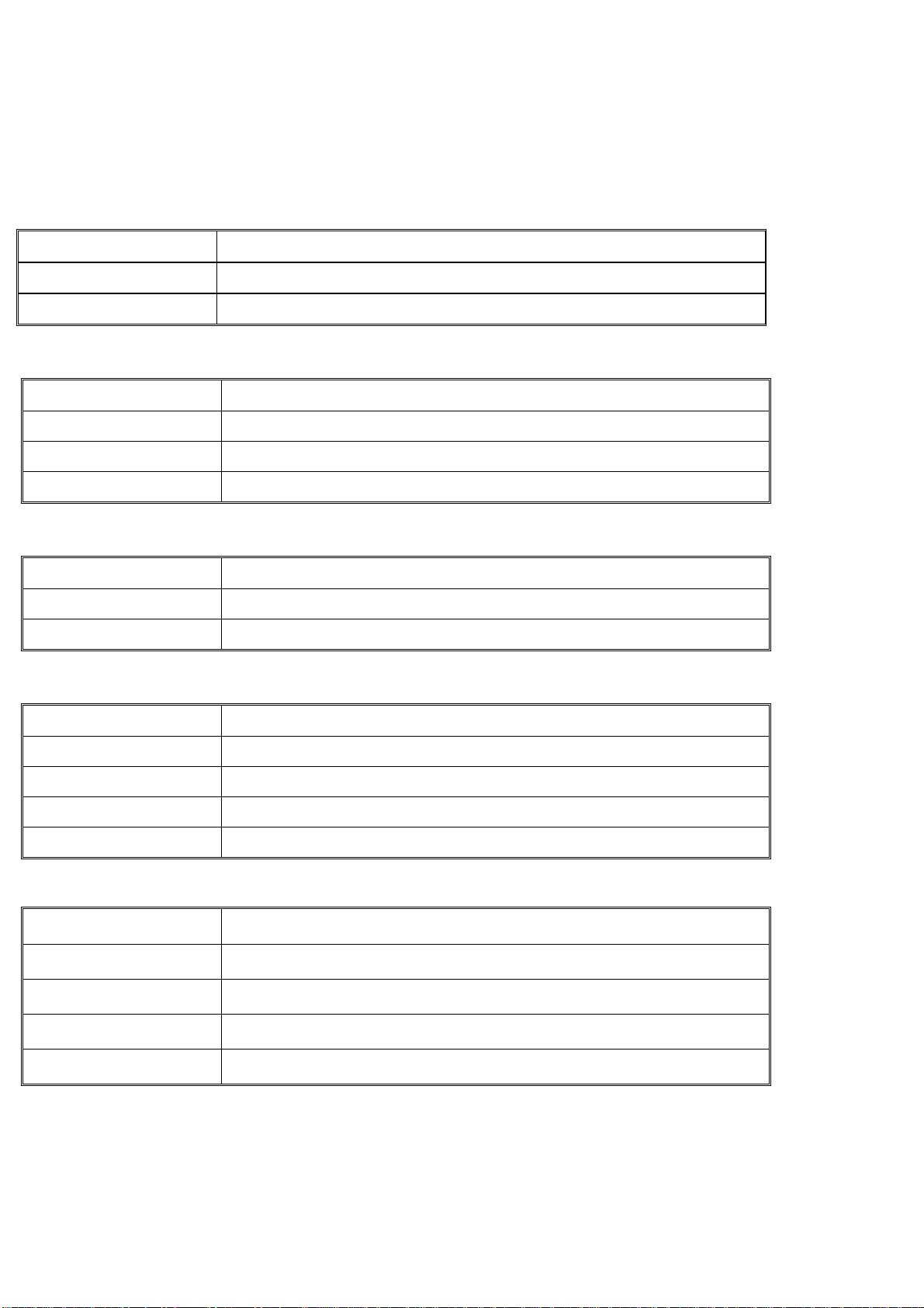
17
Standard IEC 60945 Ed4 (2002-08)
Number of panels Standard max 9 pcs in one system
Network Star and Tree network topology.
Interface RJ45 port 10/100
LAN cable CAT5e - CAT7 twisted (568b)
Power Requirements Power input: 24VDC (18-30VDC)
Power consumption: <3.5W
Physical Characteristics Casing: IP22 protection
Dimensions(WxHxD): 147x160x43,4 mm (5.8x6.3x1.7 in)
Weight: 500g (1.1 pound)
Installation: Table mounting from front
Environmental Limits Operating Temperature: -15 to 50°C(5 to 120°F)
Ambient Relative Humidity: 0 to 95% (non-condensing)
Compass Safe distance Standard: 40 cm
Steering: 30 cm
Cerificates DNV
Standard IEC 60945 Ed4 (2002-08)
Number of panels Standard max 2 pcs to each Main Operation Panel
Network Direct connection to Main Operation Panel.
Interface Phoenix he/she connector 3,81 pitch
Cable 5 wire + shielded, connected 1 to 1
Power Requirements N/A
Physical Characteristics Casing: IP22 protection
Dimensions(WxHxD): 96x96x25 mm (3.78x3.78x0.98 in)
Weight: 100g (0.22 pound)
Installation: Table mounting from front
Environmental Limits Operating Temperature: -15 to 50°C(5 to 120°F)
Ambient Relative Humidity: 0 to 95% (non-condensing)
Compass Safe distance Standard: 45 cm
Steering: 35 cm
Cerificates DNV
2.2 Main Operation Panel
2.3 Slave Operation Panel

18
Tested according to IEC 60945 Ed4 (2002-08)
IEC 60092-101, -504
IEC 60068-2-1, -2-2, -2-30
Network Wireless connection through Access Point
Interface Standard: IEEE 802.11b
Frequency: 2.4 GHz
Data Rate: Up to 11 Mbps with automatic fallback
Modulation: CCK (11/5 Mbps), DQPSK (2 Mbps), DBPSK
(1Mbps)
Transmit Power: 16 dBm typical
Receive sensitivity:
– 1Mbps: -92 dBm
– 2Mbps: -89 dBm
– 5.5Mbps: -87 dBm
– 11Mbps: -82 dBm
Antenna Connector: 1 x RP-SMA
Power Requirements Battery: 4,8V (4 celle's) 1650mAh NiMh
Charger: 230 VAC, 70-150mAh, 3-10 celle's, NiCd/NimH
Physical Characteristics Casing: IP65 protection
Dimensions(WxHxD): 117x228x46,24 mm (4.6x8.97x1.82 in)
Weight: 500g (1.1 pound)
Environmental Limits Operating Temperature: -25 to 70°C(-13 to 158°F)
Ambient Relative Humidity: 0 to 95% (non-condensing)
Compass Safe Distance Standard: 35 cm
Steering: 25 cm
2.4 Wireless Operation Panel

19
KIEN1005
Standard IEEE802.3
IEEE802.3u
IEEE802.3x
IEEE802.1p
Store and forward switching mode
MAC Address Table Size 32K
Network Chain and star network topology.
Service Diagnostics: LEDs(power, link status, port rate,)
Port priority: QoS for 5th port (default high priority)
Current over-load protection: Yes(AC220V)
Reverse polarity power connection protection: Yes
Broadcast storm protection: Yes
Interface RJ45 port 5x10/100Base-TX(KIEN1005-5T)
RJ45 port 4x10/100Base-TX and Fiber port 1x100Base-FX
(KIEN1005-1S(M)-4T)
Power Requirements Power input: 24VDC (12-36VDC), 220VDC/AC
Power consumption: <3.5W
Physical Characteristics Casing: IP40 protection
Fanless design
Dimensions(WxHxD): 36.5x120x90 mm (1.44x4.72x3.54 in)
Weight: 300g (0.66 pound)
Installation: DIN-35 Rail or wall mounting.
Environmental Limits Operating Temperature: -40 to 85°C(-40 to 185°F)
Storage Temperature: -40 to 85°C(-40 to 185°F)
Ambient Relative Humidity: 0 to 95% (non-condensing)
Approvals IEC61000-4-2(ESD): ±8KV contact discharge, ±15KV air discharge
IEC61000-4-3(RS): 10V/M (80-1000MHz)
IEC61000-4-4(EFT): ±4KV power line, ±2KV data line
IEC61000-4-5(Surge): power line ±4KV CM/ ±2KV DM, data line
±2KV IEC61000-4-6(CS):3V(10KHZ-150KHZ),10V(150KHz-
80MHz)
IEC61000-4-8(Power frequency magnetic field):100A/m cont.
1000A/m, 1s to 3s
Cerificates DNV,CE, FCC, UL, RoHS
2.5 Switch
20
High Sensitive Receiver for Wireless Operation Panel
REGULATORY/ COMPLIANCE INFORMATION
Wireless Approvals FCC, IC, CE
RoHs Compliance Yes
IP/NEMA Compliance IP67/ NEMA 6
DIAMETER RANGE PERFORMANCE
11Mbps 200m
5.5Mbps 400m
2Mbps 800m
1Mbps 1600m
RADIO OPERATING
Frequency 2412-2464 MHz
TX Power 15dBm (20dBm EIRP including Antenna)
RX Sensitivity -90dBm @ 11Mbps
ANTENNA SPECIFICATION
Gain 5dBi Omni directional
Frequencey 2400-2485 MHz
Vertical/horizontal BW 25x360 degree
Weight 0.5Ibs (0.2Kg)
Dimension 355x15mm
PHYSICAL / ELECTRICAL / ENVIRONMETNAL
Enclosure Size 185x130x50mm
Mounting Supports masts up to 3" diameter
Weight 1.50kg
Enclosure Characteristics Solid Die cast aluminium
Operating Temperature -45C to +65C
2.6 Access Point
This manual suits for next models
5
Table of contents


