Texecom Odyssey X Series User manual

Installation Manual
External Sounder and Strobe Unit,
Wired, Wireless and Deterrent
INS627-8

03-10-2022
• Update of tamper screw instructions
• PCR 01275 required a line to be added in section 1.10 detailing the relearn process and jumper position.
• Upissued to rev 7
• Changes made in line with PCR01108
• PRO 00146 Odyssey X-BD details added

INS627-8 3/44
Content
1.0 Introduction 4 ............................................................................................................................
1.1 Backplate Variants 4 ..............................................................................................................
1.2 Covers Options 5 ....................................................................................................................
1.3 Graphic Inserts 5 ....................................................................................................................
1.4 Installation Workflow 5 ...........................................................................................................
1.5 Accessing the Unit 6 ...............................................................................................................
1.6 Removing the lid completely 10 .............................................................................................
1.7 Inserting the Odyssey X1 graphic 11 ......................................................................................
1.8 Inserting the Odyssey X3 graphic 13 ......................................................................................
1.9 Odyssey X-W (Premier Elite V2.11.X or later) Battery Insertion & Learning procedure
16 ..........................................................................................................................................
1.10 Learning the Sounder (Odyssey X-W only) 19 ......................................................................
1.11 LED Indications (Odyssey X-W only) 20 ................................................................................
1.12 Mounting the Unit (all models) 21 ........................................................................................
1.13 Spirit Level 21 ......................................................................................................................
1.14 Adjusting removal from mounting tamper 23 .......................................................................
1.15 Internal Lid Tamper 24 .........................................................................................................
1.16 Wiring the Unit 25 ................................................................................................................
1.17 Grade 3 Wiring (Odyssey X & X-B only) 27 ...........................................................................
1.18 Jumper Selection (where available) 30 .................................................................................
1.19 Backlight Wiring Options 31 .................................................................................................
1.20 Installing Multiple Wired Units 31 .........................................................................................
1.21 Odyssey X-BD 33 ..................................................................................................................
1.22 Commissioning 35 ................................................................................................................
2.0 Servicing 35 ................................................................................................................................
3.0 Safety 37 .....................................................................................................................................
3.1 Technical Specification 38 ......................................................................................................
3.2 Standards 41 ..........................................................................................................................
3.3 Warranty 42 ...........................................................................................................................

INS627-8 4/44
1.0 Introduction
Odyssey X is a new range of modular external warning devices available in
standard or backlit variants. The modular design allows for a choice of front covers
to be installed on the common backplate. Please see the specification table for full
details of each model. Features include:-
Modular design - Common backplate
Backlit variants available
High Intensity White Comfort LED's
Single or twin piezo versions (Grade 2 or 3 respectively)
Integral spirit level
Clip on hinged lid with two "park" positions for easier installation
Combined inner lid and removal from mounting tamper with adjustable
sensitivity
Adjustable mounting plates allowing "In situ" drilling
Choice of Odyssey X1 or X3 front covers
Backlight may be wired to panel outputs for increased functionality
Optional Graphic inserts for company branding
1.1 Backplate Variants
Several models are available, all are the same size and use the same covers.
Model Type
Odyssey X-B Grade 3 Sounder with Integral Backlight & Twin
piezos
Odyssey X-BE Grade 2 Sounder with Integral Backlight
Odyssey X Grade 3 Sounder & Twin piezos
Odyssey X-E Grade 2 Sounder
Odyssey X–W Wireless Sounder
Odyssey X-BD Backlit Dummy Deterrent
Odyssey X–D Dummy Sounder

INS627-8 5/44
1.2 Covers Options
Outer Colour Insert Colour Lens Colour
Black Frame X1 & X3 covers White Blue, Green, Red &
White
White Frame X1 & X3 covers White
Red Frame X3 only White Red or White
1.3 Graphic Inserts
Odyssey X sounders can accommodate a graphic insert, rather than traditional
screen printed lids. Graphic inserts can be ordered directly from Texecom.
Simply follow the instructions and submit your artwork at the following web
address. http://www.texe.com/uk/branding.php
Once you have approved and paid for the artwork, inserts will be delivered directly
to you.
1.4 Installation Workflow
Wired and Wireless Odyssey X have slightly different installation procedures,
please make sure to adhere to the following workflow to ensure trouble free
installation and commissioning of your new sounder.
Wired Wireless Backlit deterrent

INS627-8 6/44
1. Select the desired
location for the sounder
2. Install 8 core cable
from the sounder
location back to the
control panel or
expander
3. Install the sounder
4. Commission the
system
1. Install the control
panel/wireless receiver
2. Learn all other
witeless devices, and
install them in their final
locations.
3. Learn wireless
sounder
4. Install wioreless
sounder in desired
location
5. Commission system
6. Check signal security
of all wireless devices
1. Select the desired location
for the deterrent
2. If using battery power,
install the batteries and
move the power select
jumper link to battery.
3. If using a PSU to power
the device, install a
minimum 2 core cable from
the PSU and connect to the
Power in terminals.
4. Move the power select
jumper to the Line position
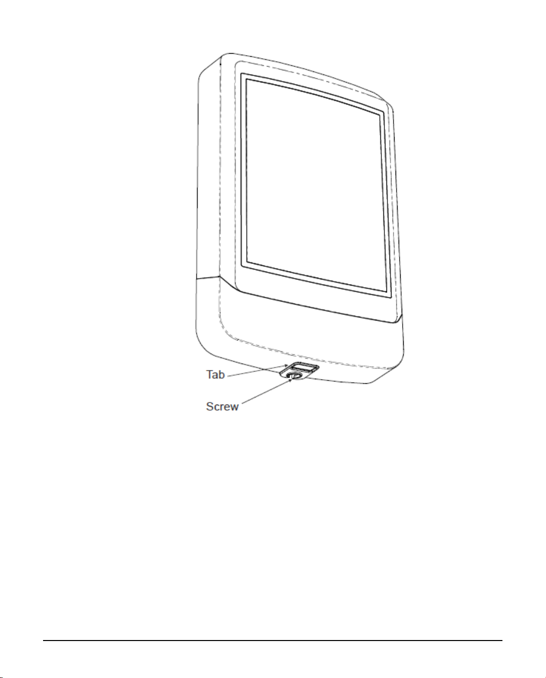
1.5 Accessing the Unit
Odyssey X1 Shown, all models are the same.
Undo the screw ( no need to remove it completely) and depress the tab to
open the lid
INS627-8 7/44
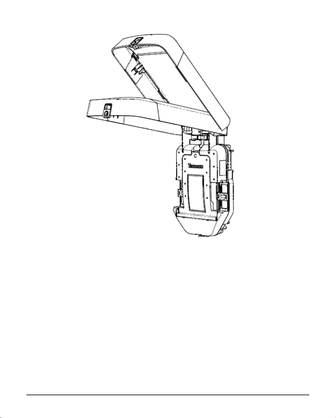
The Lid has two parked positions
INS627-8 8/44
Undo the screw and press the tab to access Wiring & Tamper

INS627-8 9/44
Inner cover open

INS627-8 10/44
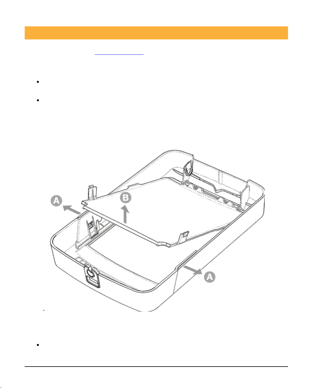
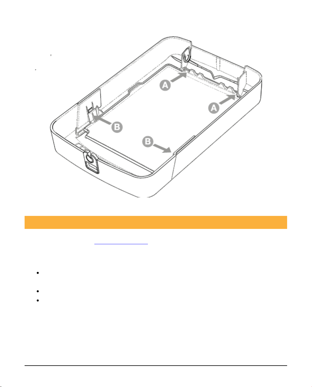
1.6 Removing the lid completely
To completely remove the lid pull the lid to the left or right at the hinge points
shown and then lift off.
INS627-8 11/44
1.7 Inserting the Odyssey X1 graphic
(available separately, see chapter 1.3)
Removing the light diffuser1.
Gently flex the two sides of the lid outwards so that the tabs release from the
lid.
Lift the light diffuser upwards to release.
N Please make sure this operation is done in a clean dry environment. where
the diffuser and lid are not likely to be scratched or damaged.
2. Insert the Graphic
Place the graphic face down in the window recess as shown.

INS627-8 12/44
3. Replace the light diffuser
Insert the light diffuser at the top edge underneath the lugs as shown.
Lower the light diffuser ensuring the two bottom side clips are engaged.
INS627-8 13/44
1.8 Inserting the Odyssey X3 graphic
(available separately, (see chapter 1.3)
1. Removing the light diffuser
Gently flex the two sides of the lid outwards to release the light diffuser at
point A.
Push the lens tabs inwards to disengage the light diffuser.
Lift the light diffuser upwards to release.
N Please make sure this operation is done in a clean dry environment. where
the diffuser and lid are not likely to be scratched or damaged.

INS627-8 14/44
2. Insert the Graphic
Place the graphic face down in the window recess as shown.

INS627-8 15/44
3. Replace the light diffuser
Insert the light diffuser at the top edge underneath the lugs as shown.
Lower the light diffuser ensuring the two lens tabs are engaged.
Press down on light diffuser shown at point C to click into place.

INS627-8 16/44
1.9 Odyssey X-W (Premier Elite V2.11.X or later)
Battery Insertion & Learning procedure
When installing a wireless sounder, the batteries should be installed and the device
learned to the panel BEFORE it is mounted in the chosen location. The sounder
should always be the last fixed device learned and installed.
N All other fixed devices should be in their desired location before learning the
sounder
The following sequence should be used.
Access the device as described on the previous pages.1.
Install the batteries into the holder2.
Connect battery pack to PCB3.
Learn sounder to panel4.

INS627-8 17/44
Make Jumper selection for LED ON/OFF5.
Make Jumper Selection for Sounder Time6.
Odyssey X-W PCB Layout

INS627-8 18/44
N All eight batteries (supplied) must be installed with the correct polarity.
Failure to do so will result in the device reporting a battery fault. If 1-2 batteries

INS627-8 19/44
are incorrectly fitted the firmware will detect this on power up and flash both
comfort LED’s for approximately 10 minutes. While the unit is in this state it will
not learn to a panel. After approximately 10 minutes the unit will power off in order
to save energy.
1.10 Learning the Sounder (Odyssey X-W only)
As with all Ricochet enabled devices, the sounder should be learned to the control
panel along with all other devices BEFORE it is installed in its final location.
The Odyssey X-W are learned to a Zone on the control panel in the same way
that Ricochet enabled detection devices are. The Zone type and Ricochet Device
Mode is automatically assigned based on the type of device being learned. In the
case of the sounder the Zone Type is set to "Custom" and the Ricochet Device
Mode is set to Device Specific. These should not be changed. Zone attributes 1 & 2
and Chime options will be ignored for Ricochet enabled Sounders.
You can learn the device from first power up following "Confirm Devices" or
from the dedicated Ricochet Learn menu.
The Odyssey X-W has no Learn Switch, learning is initiated by connecting
the batteries via the Power Jumper
To learn the Odyssey X-W to the system follow the diagram below.
If you need to delete and relearn the device, the On/Off jumper MUST be located
in the OFF position on not simply removed. Removing the jumper does not reset
the unit and it will go into and unknown state.

INS627-8 20/44
N If you need to delete the device from the system you should first put it into
"hold off " mode and remove the batteries.
N If the device will not learn to the system check that all batteries are installed
correctly.
1.11 LED Indications (Odyssey X-W only)
The Odyssey X-W LEDs aid in the installation of the device and act as status
indicators. The table below details the status of each LED indicator.
N The LED jumper has no effect on the status described below.
This manual suits for next models
9
Table of contents
Other Texecom Marine Equipment manuals

Texecom
Texecom Premier Elite 5Ci-W User manual

Texecom
Texecom Premier Elite Odyssey-W Series User manual

Texecom
Texecom Premier Elite Odyssey 5-W User manual

Texecom
Texecom Premier Elite Odyssey 1-W User manual

Texecom
Texecom Flashguard User manual

Texecom
Texecom Premier Elite 5Ci-W User manual

Texecom
Texecom Odyssey X User manual


