Norseman XGB Series Guide

Part No. 11110.Rev.1.04 March 2022 Printed in Canada
XGB Series
Explosion-Proof Forced Air Unit Heater
Installation, Operation, & Maintenance Instructions
Glycol Free Design
Special Notes
The following special notices highlight important
information in the installation, operation and maintenance
sections.
This symbol indicates a potentially hazardous
situation, which, if not avoided, can result in
personal injury or damage to the equipment.
This symbol indicates a potentially hazardous
situation, which, if not avoided, may be a shock
hazard.
This symbol indicates an imminently hazardous
situation, which, if not avoided, could result in
death or serious injury.
CAUTION
CAUTION
WARNING
WARNING
WARNING. Improper installation adjustment,
alteration, excessive vibration, service, or
maintenance can cause property damage,
injury or death. Read the installation, operating
and maintenance instructions thoroughly
before installing, operating or servicing this
equipment.

TABLE OF CONTENTS
A. General Information 3
A.1 Description .......................................................................................................................................... 3
A.2 Application ......................................................................................................................................... 3
A.3 Construction and Installation ............................................................................................... 3
A.4 Standard Product Features .................................................................................................... 3
A.5 Optional Features.......................................................................................................................... 3
A.6 Thermostats ...................................................................................................................................... 3
A.7 Motors .................................................................................................................................................... 3
A.8 Accesories........................................................................................................................................... 3
B. Pre-Installation 5
C. Installation and Mounting 5
C.1 Dimensions ......................................................................................................................................... 5
C.2 Mounting ............................................................................................................................................. 5
C.3 Mounting with Standard Kits ................................................................................................6
C.4 Outlet Louvres .................................................................................................................................8
C.5 Wiring.....................................................................................................................................................8
D. Options 9
D.1 Temperature Control ....................................................................................................................9
D.2 “AUTO/OFF/FAN-ONLY” (Optional)....................................................................................9
E. Normal Sequence of Operation 10
F. Maintenance 10
F.1 Motor....................................................................................................................................................... 10
F.2 Fan Blade............................................................................................................................................10
F.3 Heater Cabinet................................................................................................................................10
F.4 Overheat Protection...................................................................................................................10
F.5 Replacement Parts List..............................................................................................................11

3
General Information
A. GENERAL INFORMATION
A.1 Description
The small cabinet units are available with ratings from 3.75 to
10kW, and can be identied by their internally mounted motor.
The large cabinet units are available from 10kW up to 35kW. See
C.1 Dimensions, page5 for cabinet dimensions.
A.2 Application
Designed specically for heating industrial spaces where
potentially
explosive substances are or may be present. Typical hazardous
location environments include:
ࢦWater and Sewage Treatment Plants
ࢦOil Reneries
ࢦCompressor Stations
ࢦPulp and Paper Mills
ࢦPaint Storage Booths
ࢦCement Plants
ࢦMines
A.3 Construction and Installation
Norseman™ unit heaters use extra heavy wall nned tubular
steel heating elements to provide safe, efcient heat transfer to
the environment. The heater does not contain glycol.
In structures with high ceilings, other units may not have the
range of motion needed to direct air ow to the oor. The glycol-
free design of the XGB allows the unit to be tilted to a 30º angle
below the horizontal, with an additional 35º of airow redirection
provided by the outlet louver. For lateral airow, the entire louver
assembly can be rotated 90º.
A factory installed conduit seal provides the necessary isolation
between the supply and control housings. In Division 2, Zone 1
and Zone 2 applications, a eld installed conduit seal may not be
required.
To facilitate installation, the Norseman™ XGB explosion-proof
unit heaters feature the patented x-Max®housing with slide out
terminal block trolley for connection of the electrical supply.
A.4 Standard Product Features
See Figure 1 and Figure 2, page4.
ࢦCSA C/US Certied for hazardous locations. Small cabinet
units approved for Class I, Div 1 & 2, Group D; Class II, Div. 1 &
2, Groups E, F and G. Large cabinet units approved for Class I,
Div. 1 & 2, Groups C & D; Class II, Div. 1 & 2, Groups E, F & G.
NOTE: Class II and some atmospheric groups are not available
in every kW rating.
ࢦZone marking available.
ࢦRatings from 3.75 to 35kW.
ࢦ208 to 600V, 1 or 3 phase
ࢦLow watt density extra heavy wall tubular steel nned
heating elements with nickel plated nish
ࢦGlycol-free design allows the heater to be tilted 30º downward
ࢦRotatable outlet louvers provide 35º of additional airow
redirection
ࢦPatented x-Max®housing with track and trolley system
simplies installation and servicing
ࢦHeavy duty 16 ga. Stainless steel casing
ࢦTerminals for remote thermostat connection
ࢦDual automatic reset high limits
ࢦContactor derated for extended service life
ࢦIsolated supply connection housing eliminates the need for
conduit seals
A.5 Optional Features
ࢦBuilt-in, externally adjustable thermostat
ࢦBuilt-in disconnect
ࢦMoisture-resistant construction
ࢦ“AUTO/OFF/FAN-ONLY” switch
ࢦPilot light
ࢦManual reset high limit
A.6 Thermostats
Thermon offers a wide variety of explosion-proof thermostats to
suit most every need. Norseman™ unit heaters are available with
optional built-in, externally adjustable, bulb type thermostats
which are eld-convertible to tamper-proof. Thermostats for
remote mounting can also be provided on request.
A.7 Motors
Fractional horsepower, 1725RPM explosion-proof motor with
double shielded ball bearings and built-in thermal overload. Small
cabinet units use 1/12 hp motor approved for Class I, Group D;
Class II, Group E, F, and G. Large cabinet units use 1/2 hp motor
approved for Class I, Groups C and D; Class II, Groups E, F & G, as
standard.
A.8 Accesories
Norseman™ explosion-proof unit heaters readily adapt to
most mounting requirements. Each heater is equipped with a
basic swivel bracket that is compatible with any of the optional
mounting kits.
Optional mounting kits allow the unit to be installed on a wall
ceiling, 3" pipe, or oor stand. Each mounting conguration
provides maximum exibility for outlet ow direction. The swivel
bracket (standard on all heaters) features holes for afxing a
safety chain.

4
General Information
Edmonton Head Office & Factory
5918 Roper Road, Edmonton, Alberta, Canada T6B 3E1
P 780.466.3178 F 780.468.5904 Toll Free 1.800.661.8529
Part No. 11110 - Rev. 01
Installation, Operation & Maintenance Instructions for
NorsemanTM XGB Explosion-Proof Unit Heater
3.75 - 35kW, 60 Hz Units
1.0 GENERAL INFORMATION
DESCRIPTION
CCI Thermal’s XGB explosion-proof unit heater is the latest addition
to the NORSEMAN™ line of hazardous location heating products.
The small cabinet units are available with ratings from 3.75 – 10kW,
and can be identified by their internally mounted motor. The large
cabinet units (shown below) are available from 10kW up to 35kW.
See section 3.1 for cabinet dimensions.
APPLICATION
Designed specifically for heating industrial spaces where potentially
explosive substances are or may be present. Typical hazardous
location environments include:
• Water and Sewage Treatment Plants
• Oil Refineries
• Compressor Stations
• Pulp and Paper Mills
• Paint Storage Booths
• Cement Plants
• Mines
CONSTUCTION AND INSTALLATION
CCI Thermal’s NORSEMAN™ unit heaters use extra heavy wall
finned tubular steel heating elements to provide safe, efficient heat
transfer to the environment. The heater does not contain glycol,
decreasing maintenance costs.
Flow adjustment… in structures with high ceilings, other units may
not have the range of motion needed to direct air flow to the floor.
The glycol-free design of the XGB allows the unit to be tilted to a 30º
angle below the horizontal, with an additional 35º of airflow
redirection provided by the outlet louver. For lateral airflow, the entire
louver assembly can be rotated 90º.
No conduit seal required… a factory installed conduit seal
provides the necessary isolation between the supply and control
housings. In Division 2, Zone 1 and Zone 2 applications, a field
installed conduit seal may not be required.
Simplified wiring… to facilitate installation, the NORSEMAN™
explosion-proof unit heaters feature the patented x-Max® housing
with slide out terminal block trolley for connection of the electrical
supply.
STANDARD PRODUCT FEATURES
• CSA C/US Certified for hazardous locations. Small cabinet units
approved for Class I, Div 1 & 2, Group D; Class II, Div. 1 & 2,
Groups E, F and G. Large cabinet units approved for Class I, Div. 1
& 2, Groups C & D; Class II, Div. 1 & 2, Groups E, F & G.
Note: Class II and some atmospheric groups are not available in
every kW rating.
• Optional Zone marking available.
• Ratings from 3.75 – 35kW.
• 208 – 600V, 1 or 3 phase
• Low watt density extra heavy wall tubular steel finned heating
elements with nickel plated finish
• Glycol-free design allows the heater to be tilted 30º downward
• Rotatable outlet louvers provide 35º of additional airflow redirection
• Patented x-Max® housing with track and trolley system simplifies
installation and servicing
• Heavy duty 16 ga. Stainless steel casing
• Terminals for remote thermostat connection
• Dual automatic reset high limits
• Contactor derated for extended service life
• Isolated supply connection housing eliminates the need for conduit
seals
OPTIONAL FEATURES
• Built-in, externally adjustable thermostat
• Built-in disconnect
• Moisture-resistant construction
• “Auto/off/fan-only” switch
• Pilot light
• Manual reset high limit
THERMOSTATS
CCI Thermal offers a wide variety of explosion-proof thermostats to
suit most every need. NORSEMAN™ unit heaters are available with
optional built-in, externally adjustable, bulb type thermostats which
are field-convertible to tamper-proof. Thermostats for remote
mounting can also be provided on request.
MOTORS
Fractional horsepower, 1725 rpm explosion-proof motor with double
shielded ball bearings and built-in thermal overload. Small cabinet
units use 1/12 hp motor approved for Class I, Group D; Class II,
Group E, F, and G. Large cabinet units use 1/2 hp motor approved
for Class I, Groups C and D; Class II, Groups E, F & G, as standard.
ACCESSORIES
NORSEMAN™explosion-proof unit heaters readily adapt to most
mounting requirements. Each heater is equipped with a basic swivel
bracket that is compatible with any of the optional mounting kits.
Optional mounting kits allow the unit to be installed on a wall ceiling,
3” pipe, or floor stand. Each mounting configuration provides
maximum flexibility for outlet flow direction. The swivel bracket Figure 2 - XGB Heater Dimensions
2.0 PRE-INSTALLATION
2.1 Inspect the heater for possible damage due to shipping and
handling. Claims for shipping damages shall be placed with the
carrier.
2.2 Check the heater nameplate to ensure that the heater area
classification and temperature code are suitable for the hazardous
area classification.
2.3 Verify that the nameplate voltage, phase and wattage are as
ordered and are the same as the electrical power supply available.
DO NOT CONNECT THE XGB UNIT HEATER TO A SUPPLY
VOLTAGE OTHER THAN THAT SHOWN ON THE PRODUCT
NAMEPLATE.
3.0 INSTALLATION AND MOUNTING
The heater must be installed by qualified personnel in strict
compliance with the electrical code.
3.1 DIMENSIONS
Table 1: Dimensions and Weights (See Fig. 2)
3.2 MOUNTING
3.2.1 NORSEMAN™ explosion-proof unit heaters can be mounted
to a ceiling, wall 3” pipe, or floor stand. Ensure that the mounting
surface is sufficiently strong to support the heater, which, depending
on the model, could weigh up to 185lbs, (84kg). See 3.1 for heater
dimensions and weights.
3.2.2 The heater must be positioned with a minimum 15 cm (6”) side
clearance from all surrounding surfaces and must be mounted at
least 61 cm (24”) from the floor for small cabinet units, or 2440 cm
(96”) from the floor for large cabinet units. It is best to maximize
clearances to allow freedom of rotation. Ensure that airflow into
and out of the unit is not restricted.
3.2.3 All mounting studs, bolts, nuts and other fasteners shall be
secured so that there is no possibility of loosening over prolonged
periods. Periodically inspect at regular intervals and retighten if
necessary.
3.2.4 All standard mounting kits are designed to support the heater
on its centre of gravity and to allow for 30º tilt in the vertical direction
and 360 º rotation in the horizontal. Note that horizontal rotation is
fixed after the ceiling bracket is bolted to its support.
3.2.5 For specific mounting instructions refer to the appropriate
paragraph of section 3.3.
3.2.6 If lifting with slings, take special care not to damage the casing.
3.2.7 For large cabinet units, leave the heater on the shipping skid
and use the skid as a lifting platform to facilitate installation of the
heater.
3.3 MOUNTING WITH STANDARD KITS
3.3.1 CEILING MOUNTING
a) Install the ceiling bracket to the mounting surface with the desired
orientation. Ensure that ‘LINE A” (Figure 3), a line drawn
perpendicular to the bolt holes in the mounting bar, is pointed in the
desired direction of airflow. The ceiling bracket must be secured to
the mounting surface using as many as six (but not less than two)
5/8” fasteners (not provided). Make certain that lockwashers are
used under all nuts or lag bolts.
b) Hoist the heater up to the ceiling bracket. Line up the large centre
hole in the swivel bracket with the large hole in the mounting bar.
c) Insert the 1/2” bolt and loosely secure with nut and washers
provided. Tilt the heater at the desired angle to the horizontal and
secure with the 3/8” bolt. Tighten the 1/2” bolt.
Figure 3 - Ceiling Mounting
3.3.2 WALL MOUNTING
a) Install the ceiling bracket to the wall bracket with the desired
orientation. Ensure that “LINE A” (Figure 4), a line drawn
perpendicular to the bolt holes in the mounting bar, is pointed in the
desired direction of air flow. Secure the wall bracket to the mounting
surface. The wall bracket must be secured to the mounting surface
using as many as six (but not less than four) 5/8” fasteners (not
provided). Make certain that lockwashers are used under all nuts or
lag bolts.
b) Follow steps b) and c) outlined in 3.3.1.
Figure 4 - Wall Mounting
STANDARD FEATURES, SMALL CABINET UNIT:
1) 1/12 hp explosion-proof motor
2) Inlet guard
3) Extra heavy wall tubular steel finned heating elements with
nickel plated finish
4) Patented x-Max® explosion-proof terminal housing
5) 120V control circuit includes:
• Derated magnetic contactor
• Dual automatic reset high limits
• Transformer
6) Heavy duty 16 ga. stainless steel casing
7) Outlet louver assembly
8) Swivel bracket
9) Factory installed conduit seal
10)Supply connection housing
11)Terminal block for supply wiring and thermostat connection
STANDARD FEATURES, LARGE CABINET UNIT:
1) 1/2 hp explosion-proof motor
2) Inlet wire guard
3) Extra heavy wall tubular steel finned heating elements with
nickel plated finish
4) Patented x-Max® explosion-proof terminal housing
5) 120V control circuit includes:
• Derated magnetic contactor
• Dual automatic reset high limits
• Transformer
• Fan delay relay
• Control fuse
6) Heavy duty 16 ga. stainless steel casing
7) Outlet louver assembly
8) Swivel bracket
9) Factory installed conduit seal
10)Supply connection housing
11)Terminal block for supply wiring and thermostat connection
12)Motor mount
13)Motor mount casing
3.3.3 POST MOUNTING
a) Install the ceiling bracket to the wall bracket with the desired
orientation. Ensure that “LINE A” (Figure 5), a line drawn
perpendicular to the bolt holes in the mounting bar, is pointed in the
desired direction of air flow. Secure the wall bracket to the post using
the 1/2” U-bolts, nuts and washers supplied. Make certain the
lockwashers are used under all nuts or lag bolts.
b) Follow steps b) and c) outlined in 3.3.1.
Figure 5 - Post Mounting
3.3.4 FLOOR STAND MOUNTING
a) At times adequate support for the heater may not be available
within the structure of the space to be heated. In this situation, the
floor mount stand may be desirable. Telescoping square tubing on a
support base allows the unit to be positioned at the desired height
above the floor anywhere between 1.8 m (6’) to 3 m (10’).
b) Position the base of the stand on the floor in the desired
orientation. Ensure that “LINE A” (Figure 6), a line drawn
perpendicular to the bolt holes in the mounting bar, is pointed in the
desired direction of air flow.
c) Next, the stand is to be lagged to a solid floor to prevent the unit
from toppling. Four 11/16” diameter holes are provided in the base of
the stand for this purpose.
d) Raise the mounting frame to the desired height and secure to the
base using the hardware supplied.
e) Hoist the heater up to the mounting frame.
f) Insert the 1/2” bolt and loosely secure with nut and lockwashers
provided. Tilt the heater at the desired angle to the horizontal and
secure with the 3/8” bolt. Tighten the 1/2” bolt.
Figure 6 - Floor Mounting Stand
3.4 OUTLET LOUVRES
3.4.1 A louvred grill on the heater outlet end is supplied as standard.
The louver assembly may be positioned either horizontally or
vertically for maximum flexibility.
3.4.2 Standard heaters are shipped with the louvers in the horizontal
position. To change the orientation of the louvers to vertical, remove
the three mounting screws securing the louver assembly to the
cabinet and rotate the louver 90º to the desired direction.
3.5 WIRING
CAUTION: Whenever hazardous materials are present, ensure
that the terminal housing covers, plugs, etc., are secured (but
not over-tightened) before powering the heater.
All circuits must be in the open position before removing
junction or terminal box covers.
3.5.1 The heater must be installed by qualified personnel in strict
compliance with the electrical code.
3.5.2 All heaters are factory pre-wired and ready for direct
connections to the power supply leads.
3.5.3 The heater must be individually fused, preferably with Class J
time-delay fuses for maximum safety. Unless stated otherwise in
your local code, fuse size shall be 125% of line current or next size
larger. See Table 2 for recommendations.
3.5.4 Use approved conduit and conduit seals are required by the
code for the hazardous location.
3.5.5 The NORSEMAN™ explosion-proof unit heaters are equipped
with a factory installed conduit seal between the control and supply
housings. In Division 2, Zone 1 and Zone 2 applications, a field
installed conduit seal may not be required.
3.5.6 Supply wiring connections are made by accessing the over of
the side mounted supply connection housing (terminal box). Slide
the control trolley out of the housing just enough to access the
terminal block (Figure 8).
3.5.7 Connect the power leads to terminals marked L1and L2 for
single phase and L1, L2 and L3 for three phaseheaters making certain
to leave some excess wire to ensure that the leads may slide back
into the housing with the trolley. See Figure 9 for control circuit and
Figure 10 for suggested wiring. Exercise care to avoid damage to
wires caused by threads on the housing.
Table 2: Recommended Fuse Sizes
Figure 9A - Small Cabinet XGB Wiring Schematic
Figure 9B - Large Cabinet XGB Wiring Schematic
3.5.8 Connect the ground wire to the ground connection located in
the supply connection housing; once again, making sure that the
wire is sufficiently long to slide back into the housing with the trolley.
See Figure 10.
Figure 10 - Supply Connection
3.5.9 Due to the presence of hazardous materials, ensure that
the terminal housing covers, plugs, etc., are secured (but not
over-tightened) before powering the heater.
4.0 TEMPERATURE CONTROL
4.1 BUILT-IN THERMOSTAT (OPTIONAL)
When specified, the unit comes equipped with a built-in thermostat
pre-wired to all other standard controls. Set the temperature to the
desired operating condition.
4.2 REMOTE THERMOSTAT (OPTIONAL)
Install the XT thermostat in accordance with the instruction sheet
provided. Terminals “T1” and “T2” in the heater supply housing are
provided for connection to the remote thermostat and are pre-wired
to the rest of the control circuit. Remove the jumper wire between
“T1” and “T2” and connect the thermostat to these terminals. (Refer
to Figure 9). Set the temperature to the desired operating condition.
5.0 “AUTO / OFF / FAN-ONLY” SWITCH (OPTIONAL)
If ordered, a factory installed “auto / off / fan-only” switch may be
included on the heater. The “fan-only” feature allows the heater to
cycle in a “heat” mode dictated by the controlling thermostat, even
though the fan is operating continuously.
6.0 NORMAL SEQUENCE OF OPERATION
6.1 The heater must be properly mounted and wired in accordance
with the instructions contained in this manual. The fan blade must be
free to rotate with no obstruction to air inlet or outlet areas.
6.2 Energize the heater at the rated supply voltage.
6.3 Assuming that the thermostat calls for heat, i.e. the thermostat is
set to a higher temperature that ambient:
a) The main contactor will energize the elements and the fan motor.
b) After the inlet air temperature rises to the set point of the
thermostat, the thermostat contacts will open and the main contactor
will de-energize the elements and the fan motor.
Note: The large cabinet XGB incorporates a fan delay feature in both
the “ON” and “OFF” cycles. This is a desirable feature as it allows
the heater to come to temperature before the fan operates (no cold
blasts) and to cool down the “OFF” cycle (longer life for control
components and motor). Delay “ON” is 15 - 40 seconds and delay
“OFF” is 60 -160 seconds.
6.4 The cycle described above will repeat when the ambient
temperature falls below the thermostat set point.
IMPORTANT:
THE PROPER MOTOR/FAN ROTATION, VIEWED FROM THE
REAR OF THE HEATER IS COUNTER CLOCKWISE FOR THE
SMALL CABINET UNITS AND CLOCKWISE FOR THE LARGE
CABINET UNITS, AS INDICATED BY THE FAN ROTATION
LABEL ON THE HEATER. INCORRECT ROTATION OF THE FAN
WILL CAUSE THE HEATER TO OVERHEAT AND CYCLE ON THE
HIGH LIMITS. CONSULT FACTORY IN CASE OF INCORRECT
ROTATION.
7.0 MAINTENANCE
7.1 The NORSEMAN™ explosion-proof unit heaters are designed
and constructed to operate in tough industrial applications with a
minimum of maintenance. However, some routine maintenance is
recommended to extend the life of the heater and its components.
Always disconnect the electrical supply before performing any
maintenance.
7.2 Periodically inspect the heater installation to ensure that all
connections, fittings, plugs, screws, covers, etc. are tight and free of
corrosion.
7.3 Check the inside of the cabinet and around the element fins for
dust build-up and debris, especially after seasonal shutdowns.
Clean with an air blast or vacuum. Ensure that nothing is restricting
the air flow into the unit and that the fan blade is free to rotate.
7.4 MOTOR
The motor supplied with the small cabinet units is approved for Class
1, Group D, Class II, Group E, F & G, T3B temperature code. The
motor supplied with the large cabinet units is approved for Class I,
Group C & D, Class II, Group E, F & G, T3B temperature code. All
motors have internal thermal protection to eliminate motor
overheating.
7.5 FAN BLADE
Visually inspect the fan blade to ensure it is free to rotate and
accidental damage has not occurred. If bent or damaged, a factory
balanced blade should be installed so that the rated airflow is
maintained. A damaged fan blade may not deliver the required
airflow over the elements, resulting in cycling on the high limit which
can significantly reduce the life of the contactor and the high limit.
7.6 HEATER CABINET
The XGB unit heater cabinet is stainless steel for superior corrosion
resistance. We recommend the cabinet be wiped down periodically
using a mild detergent.
7.7 OVERHEAT PROTECTION
In the event of fan failure, motor damage, excessive dust build-up or
restricted inlet airflow, the heater temperature may rise, causing the
limit controls to open, breaking the power supply to the heater. All
units are equipped with two automatic reset high limit controls.
Cycling of the high limits should not be permitted.
Should this occur, the unit should be inspected to determine the
cause of the cycling and the condition should be corrected.
8.0 REPLACEMENT PARTS LIST
The replacement parts list is included for reference only. Due to the
delicate nature of explosion-proof design, XGB unit heaters are not
field serviceable. Should any problem arise, return the unit to the
factory for service by trained personnel.
SMALL CABINET UNITS:
LARGE CABINET UNITS:
A CCI Thermal XTK thermostat kit may be purchased to replace a
broken thermostat. Refer to installation instructions provided with
the kit.
Transformers
High Limits
Motor
Contactor
Fan Blade
208V units
240V units
480V units
600V units
T2C T-Code units
T3A T-Code units
T3B T-Code units
All units
All units
10 & 7.5kW units
5 & 3.75kW units
MO250O
MO250Q
MO250S
MO250V
C12023-11
C12023-10
C12023-10
B14302-01
42CF35AF
C11028-06
C11028-05
Transformers
High Limits
Motors
Contactor
Fan Blade
Control Fuse
208V units
240V units
480V units
600V units
T2C T-Code units
T2D T-Code units
T3A T-Code units
T3B T-Code units
208 - 480V 3Ø units
240V 1Ø units
600V units
All units
All units
All units
EXA50-23
EXA50-25
EXA50-36
EXA50-39
C12023-11
C12023-11
C12023-10
C12023-12
1699
1979
2433
42CF35AF
10873
MDL-0.6
GLYCOL
FREE
DESIGN
TERMINAL BLOCK
Figure 8 - XGB Terminal Block Trolley Figure
SIDE
LOOP
TOP
1 OR 3
Ø
SUPPLY
L3
L2
L1
C
H3
H2
H1
TO HEATING
LOAD
X1
120V T1 T2 HI-LIMITS
X2 C/AUX
C NO MOTOR
REMOVE JUMPER FOR
OPTIONAL THERMOSTAT
C
M
LINE A
CEILING BRACKET
MOUNTING BAR
3/8” Flat Washer, Lock Washer, Nut
1/2” Flat Washer, Lock Washer, Nut
MOUNTING SURFACE
11/16” Dia. Mounting Holes
3/8” bolt
1/2” bolt
SWIVEL MOUNTING BRACKET SWIVEL MOUNTING BRACKET
3” PIPE (NOT INCLUDED)
WALL BRACKET
LINE A
CEILING BRACKET
MOUNTNIG BAR
1/2” U-bolt
1/2” flat washer, lock washer, nut
5/8” flatwasher, lockwasher, nut
1/2” flat washer, lock washer, nut
3/8” flat washer, lock washer, nut
5/8” bolt
1/2” bolt
3/8” bolt MOUNTING FRAME
MOUNTING BAR
3/8” flatwasher, lockwasher, nut
1/2” flatwasher, lockwasher, nut
3/8” Bolt
1/2” Bolt
SWIVEL MOUNTING BRACKET
5/8” Bolt
5/8” flatwasher,
lockwasher, nut
LINE A
MOUNTING SURFACE
11/16” dia. mounting holes
5/8” flatwasher, lockwasher, nut
WALL BRACKET
LINE A
CEILING BRACKET
5/8” Bolt
MOUNTING BAR
3/8” flatwasher, lockwasher, nut
1/2” flatwasher, lockwasher, nut
3/8” Bolt
1/2” Bolt
SWIVEL MOUNTING BRACKET
5/8” Bolt M
H1
H2
H3
TO HEATING
LOAD
REMOVE JUMPER FOR
OPTIONAL THERMOSTAT
120V HI-LIMITS
FD
C
FD
1
3
4
5
X2 T1 T2
3ØONLY
C
3ØONLY
X1
L3 L2 L1
L1
L2
L3
1 OR 3Ø
SUPPLY
AIRFLOW
C
A
B
D1
D2
Figure 1B - Large Cabinet XGB Unit Heater Components
Figure 1A - Small Cabinet XGB Unit Heater Components
Recommended
Catalog Number kW Voltage Max Line Amps Fuse Size
(Amps)
1 Ø 3 Ø 1 Ø 3 Ø
XGB038T3B 3.7 5 208 1 9 1 1 2 5 1 5
240 1 7 1 0 2 5 1 5
480 - 6 - 1 0
600 - 5 - 1 0
XGB050T3B 5 208 2 5 1 5 3 5 2 0
240 2 2 1 3 3 0 2 0
480 - 7 - 1 0
600 - 6 - 1 0
XGB075T3A 7 . 5 208 3 7 2 2 5 0 3 0
240 3 2 1 9 4 0 2 5
480 - 1 0 - 1 5
600 - 8 - 1 0
XGB100T2C 1 0 208 2 9 4 0
240 4 3 2 5 6 0 3 5
480 - 1 3 - 2 0
600 - 1 1 - 1 5
XGB100T3B 1 0 208 - 3 0 - 4 0
240 4 7 2 6 6 0 3 5
480 - 1 3 - 2 0
600 - 1 1 - 1 5
XGB150T3B 1 5 208 - 4 4 - 6 0
240 - 3 8 - 5 0
480 - 1 9 - 2 5
600 - 1 5 - 2 0
XGB200T3B 2 0 480 - 2 5 - 3 5
600 - 2 0 - 2 5
XGB225T3A 22. 5 480 - 2 8 - 3 5
600 - 2 3 - 3 0
XGB250T2D 2 5 480 - 3 1 - 4 0
600 - 2 5 - 3 5
XGB300T2D 3 0 480 - 3 7 - 5 0
600 - 3 0 - 4 0
XGB325T2D 32.5 480 - 4 0 - 5 0
600 - 3 2 - 4 0
XGB350T2C 3 5 480 - 4 3 - 6 0
600 - 3 4 - 4 5
A B C D1 D2 Weight
lbs (kg)
Small16-7/ 8 8-7/ 8 25-3-/16 17-1/ 2 - 100
Cabinet(429)(225)(640)(445)(45)
10-15 kW
Large20-1/ 8 8-7/ 8 29-1/ 4 - 31-1/ 4 145 (66)
Cabinet(511)(225)(743)(794)20-35 kW
185 (84)
Standard Features (Small Cabinet Unit)
1) 1/12 hp explosion-proof motor
2) Inlet guard
3) Extra heavy wall tubular steel nned heating elements
with
nickel plated nish
4) Patented x-Max® explosion-proof terminal housing
5) 120V control circuit includes:
–Derated magnetic contactor
–Dual automatic reset high limits
–Transformer
6) Heavy duty 16 ga. stainless steel casing
7) Outlet louver assembly
8) Swivel bracket
9) Factory installed conduit seal
10) Supply connection housing
11) Terminal block for supply wiring and thermostat
connection
Figure 1 – Small Cabinet XGB Unit Heater Components
Standard Features (Large Cabinet Unit)
1) 1/2 hp explosion-proof motor
2) Inlet wire guard
3) Extra heavy wall tubular steel nned heating elements with
nickel plated nish
4) Patented x-Max® explosion-proof terminal housing
5) 120V control circuit includes:
–Derated magnetic contactor
–Dual automatic reset high limits
–Transformer
–Fan delay relay
–Control fuse
6) Heavy duty 16 ga. stainless steel casing
7) Outlet louver assembly
8) Swivel bracket
9) Factory installed conduit seal
10) Supply connection housing
11) Terminal block for supply wiring and thermostat connection
12) Motor mount
13) Motor mount casing
Edmonton Head Office & Factory
5918 Roper Road, Edmonton, Alberta, Canada T6B 3E1
P 780.466.3178 F 780.468.5904 Toll Free 1.800.661.8529
Part No. 11110 - Rev. 01
Installation, Operation & Maintenance Instructions for
NorsemanTM XGB Explosion-Proof Unit Heater
3.75 - 35kW, 60 Hz Units
1.0 GENERAL INFORMATION
DESCRIPTION
CCI Thermal’s XGB explosion-proof unit heater is the latest addition
to the NORSEMAN™ line of hazardous location heating products.
The small cabinet units are available with ratings from 3.75 – 10kW,
and can be identified by their internally mounted motor. The large
cabinet units (shown below) are available from 10kW up to 35kW.
See section 3.1 for cabinet dimensions.
APPLICATION
Designed specifically for heating industrial spaces where potentially
explosive substances are or may be present. Typical hazardous
location environments include:
• Water and Sewage Treatment Plants
• Oil Refineries
• Compressor Stations
• Pulp and Paper Mills
• Paint Storage Booths
• Cement Plants
• Mines
CONSTUCTION AND INSTALLATION
CCI Thermal’s NORSEMAN™ unit heaters use extra heavy wall
finned tubular steel heating elements to provide safe, efficient heat
transfer to the environment. The heater does not contain glycol,
decreasing maintenance costs.
Flow adjustment… in structures with high ceilings, other units may
not have the range of motion needed to direct air flow to the floor.
The glycol-free design of the XGB allows the unit to be tilted to a 30º
angle below the horizontal, with an additional 35º of airflow
redirection provided by the outlet louver. For lateral airflow, the entire
louver assembly can be rotated 90º.
No conduit seal required… a factory installed conduit seal
provides the necessary isolation between the supply and control
housings. In Division 2, Zone 1 and Zone 2 applications, a field
installed conduit seal may not be required.
Simplified wiring… to facilitate installation, the NORSEMAN™
explosion-proof unit heaters feature the patented x-Max® housing
with slide out terminal block trolley for connection of the electrical
supply.
STANDARD PRODUCT FEATURES
• CSA C/US Certified for hazardous locations. Small cabinet units
approved for Class I, Div 1 & 2, Group D; Class II, Div. 1 & 2,
Groups E, F and G. Large cabinet units approved for Class I, Div. 1
& 2, Groups C & D; Class II, Div. 1 & 2, Groups E, F & G.
Note: Class II and some atmospheric groups are not available in
every kW rating.
• Optional Zone marking available.
• Ratings from 3.75 – 35kW.
• 208 – 600V, 1 or 3 phase
• Low watt density extra heavy wall tubular steel finned heating
elements with nickel plated finish
• Glycol-free design allows the heater to be tilted 30º downward
• Rotatable outlet louvers provide 35º of additional airflow redirection
• Patented x-Max® housing with track and trolley system simplifies
installation and servicing
• Heavy duty 16 ga. Stainless steel casing
• Terminals for remote thermostat connection
• Dual automatic reset high limits
• Contactor derated for extended service life
• Isolated supply connection housing eliminates the need for conduit
seals
OPTIONAL FEATURES
• Built-in, externally adjustable thermostat
• Built-in disconnect
• Moisture-resistant construction
• “Auto/off/fan-only” switch
• Pilot light
• Manual reset high limit
THERMOSTATS
CCI Thermal offers a wide variety of explosion-proof thermostats to
suit most every need. NORSEMAN™ unit heaters are available with
optional built-in, externally adjustable, bulb type thermostats which
are field-convertible to tamper-proof. Thermostats for remote
mounting can also be provided on request.
MOTORS
Fractional horsepower, 1725 rpm explosion-proof motor with double
shielded ball bearings and built-in thermal overload. Small cabinet
units use 1/12 hp motor approved for Class I, Group D; Class II,
Group E, F, and G. Large cabinet units use 1/2 hp motor approved
for Class I, Groups C and D; Class II, Groups E, F & G, as standard.
ACCESSORIES
NORSEMAN™explosion-proof unit heaters readily adapt to most
mounting requirements. Each heater is equipped with a basic swivel
bracket that is compatible with any of the optional mounting kits.
Optional mounting kits allow the unit to be installed on a wall ceiling,
3” pipe, or floor stand. Each mounting configuration provides
maximum flexibility for outlet flow direction. The swivel bracket Figure 2 - XGB Heater Dimensions
2.0 PRE-INSTALLATION
2.1 Inspect the heater for possible damage due to shipping and
handling. Claims for shipping damages shall be placed with the
carrier.
2.2 Check the heater nameplate to ensure that the heater area
classification and temperature code are suitable for the hazardous
area classification.
2.3 Verify that the nameplate voltage, phase and wattage are as
ordered and are the same as the electrical power supply available.
DO NOT CONNECT THE XGB UNIT HEATER TO A SUPPLY
VOLTAGE OTHER THAN THAT SHOWN ON THE PRODUCT
NAMEPLATE.
3.0 INSTALLATION AND MOUNTING
The heater must be installed by qualified personnel in strict
compliance with the electrical code.
3.1 DIMENSIONS
Table 1: Dimensions and Weights (See Fig. 2)
3.2 MOUNTING
3.2.1 NORSEMAN™ explosion-proof unit heaters can be mounted
to a ceiling, wall 3” pipe, or floor stand. Ensure that the mounting
surface is sufficiently strong to support the heater, which, depending
on the model, could weigh up to 185lbs, (84kg). See 3.1 for heater
dimensions and weights.
3.2.2 The heater must be positioned with a minimum 15 cm (6”) side
clearance from all surrounding surfaces and must be mounted at
least 61 cm (24”) from the floor for small cabinet units, or 2440 cm
(96”) from the floor for large cabinet units. It is best to maximize
clearances to allow freedom of rotation. Ensure that airflow into
and out of the unit is not restricted.
3.2.3 All mounting studs, bolts, nuts and other fasteners shall be
secured so that there is no possibility of loosening over prolonged
periods. Periodically inspect at regular intervals and retighten if
necessary.
3.2.4 All standard mounting kits are designed to support the heater
on its centre of gravity and to allow for 30º tilt in the vertical direction
and 360 º rotation in the horizontal. Note that horizontal rotation is
fixed after the ceiling bracket is bolted to its support.
3.2.5 For specific mounting instructions refer to the appropriate
paragraph of section 3.3.
3.2.6 If lifting with slings, take special care not to damage the casing.
3.2.7 For large cabinet units, leave the heater on the shipping skid
and use the skid as a lifting platform to facilitate installation of the
heater.
3.3 MOUNTING WITH STANDARD KITS
3.3.1 CEILING MOUNTING
a) Install the ceiling bracket to the mounting surface with the desired
orientation. Ensure that ‘LINE A” (Figure 3), a line drawn
perpendicular to the bolt holes in the mounting bar, is pointed in the
desired direction of airflow. The ceiling bracket must be secured to
the mounting surface using as many as six (but not less than two)
5/8” fasteners (not provided). Make certain that lockwashers are
used under all nuts or lag bolts.
b) Hoist the heater up to the ceiling bracket. Line up the large centre
hole in the swivel bracket with the large hole in the mounting bar.
c) Insert the 1/2” bolt and loosely secure with nut and washers
provided. Tilt the heater at the desired angle to the horizontal and
secure with the 3/8” bolt. Tighten the 1/2” bolt.
Figure 3 - Ceiling Mounting
3.3.2 WALL MOUNTING
a) Install the ceiling bracket to the wall bracket with the desired
orientation. Ensure that “LINE A” (Figure 4), a line drawn
perpendicular to the bolt holes in the mounting bar, is pointed in the
desired direction of air flow. Secure the wall bracket to the mounting
surface. The wall bracket must be secured to the mounting surface
using as many as six (but not less than four) 5/8” fasteners (not
provided). Make certain that lockwashers are used under all nuts or
lag bolts.
b) Follow steps b) and c) outlined in 3.3.1.
Figure 4 - Wall Mounting
STANDARD FEATURES, SMALL CABINET UNIT:
1) 1/12 hp explosion-proof motor
2) Inlet guard
3) Extra heavy wall tubular steel finned heating elements with
nickel plated finish
4) Patented x-Max® explosion-proof terminal housing
5) 120V control circuit includes:
• Derated magnetic contactor
• Dual automatic reset high limits
• Transformer
6) Heavy duty 16 ga. stainless steel casing
7) Outlet louver assembly
8) Swivel bracket
9) Factory installed conduit seal
10)Supply connection housing
11)Terminal block for supply wiring and thermostat connection
STANDARD FEATURES, LARGE CABINET UNIT:
1) 1/2 hp explosion-proof motor
2) Inlet wire guard
3) Extra heavy wall tubular steel finned heating elements with
nickel plated finish
4) Patented x-Max® explosion-proof terminal housing
5) 120V control circuit includes:
• Derated magnetic contactor
• Dual automatic reset high limits
• Transformer
• Fan delay relay
• Control fuse
6) Heavy duty 16 ga. stainless steel casing
7) Outlet louver assembly
8) Swivel bracket
9) Factory installed conduit seal
10)Supply connection housing
11)Terminal block for supply wiring and thermostat connection
12)Motor mount
13)Motor mount casing
3.3.3 POST MOUNTING
a) Install the ceiling bracket to the wall bracket with the desired
orientation. Ensure that “LINE A” (Figure 5), a line drawn
perpendicular to the bolt holes in the mounting bar, is pointed in the
desired direction of air flow. Secure the wall bracket to the post using
the 1/2” U-bolts, nuts and washers supplied. Make certain the
lockwashers are used under all nuts or lag bolts.
b) Follow steps b) and c) outlined in 3.3.1.
Figure 5 - Post Mounting
3.3.4 FLOOR STAND MOUNTING
a) At times adequate support for the heater may not be available
within the structure of the space to be heated. In this situation, the
floor mount stand may be desirable. Telescoping square tubing on a
support base allows the unit to be positioned at the desired height
above the floor anywhere between 1.8 m (6’) to 3 m (10’).
b) Position the base of the stand on the floor in the desired
orientation. Ensure that “LINE A” (Figure 6), a line drawn
perpendicular to the bolt holes in the mounting bar, is pointed in the
desired direction of air flow.
c) Next, the stand is to be lagged to a solid floor to prevent the unit
from toppling. Four 11/16” diameter holes are provided in the base of
the stand for this purpose.
d) Raise the mounting frame to the desired height and secure to the
base using the hardware supplied.
e) Hoist the heater up to the mounting frame.
f) Insert the 1/2” bolt and loosely secure with nut and lockwashers
provided. Tilt the heater at the desired angle to the horizontal and
secure with the 3/8” bolt. Tighten the 1/2” bolt.
Figure 6 - Floor Mounting Stand
3.4 OUTLET LOUVRES
3.4.1 A louvred grill on the heater outlet end is supplied as standard.
The louver assembly may be positioned either horizontally or
vertically for maximum flexibility.
3.4.2 Standard heaters are shipped with the louvers in the horizontal
position. To change the orientation of the louvers to vertical, remove
the three mounting screws securing the louver assembly to the
cabinet and rotate the louver 90º to the desired direction.
3.5 WIRING
CAUTION: Whenever hazardous materials are present, ensure
that the terminal housing covers, plugs, etc., are secured (but
not over-tightened) before powering the heater.
All circuits must be in the open position before removing
junction or terminal box covers.
3.5.1 The heater must be installed by qualified personnel in strict
compliance with the electrical code.
3.5.2 All heaters are factory pre-wired and ready for direct
connections to the power supply leads.
3.5.3 The heater must be individually fused, preferably with Class J
time-delay fuses for maximum safety. Unless stated otherwise in
your local code, fuse size shall be 125% of line current or next size
larger. See Table 2 for recommendations.
3.5.4 Use approved conduit and conduit seals are required by the
code for the hazardous location.
3.5.5 The NORSEMAN™ explosion-proof unit heaters are equipped
with a factory installed conduit seal between the control and supply
housings. In Division 2, Zone 1 and Zone 2 applications, a field
installed conduit seal may not be required.
3.5.6 Supply wiring connections are made by accessing the over of
the side mounted supply connection housing (terminal box). Slide
the control trolley out of the housing just enough to access the
terminal block (Figure 8).
3.5.7 Connect the power leads to terminals marked L1and L2 for
single phase and L1, L2 and L3 for three phaseheaters making certain
to leave some excess wire to ensure that the leads may slide back
into the housing with the trolley. See Figure 9 for control circuit and
Figure 10 for suggested wiring. Exercise care to avoid damage to
wires caused by threads on the housing.
Table 2: Recommended Fuse Sizes
Figure 9A - Small Cabinet XGB Wiring Schematic
Figure 9B - Large Cabinet XGB Wiring Schematic
3.5.8 Connect the ground wire to the ground connection located in
the supply connection housing; once again, making sure that the
wire is sufficiently long to slide back into the housing with the trolley.
See Figure 10.
Figure 10 - Supply Connection
3.5.9 Due to the presence of hazardous materials, ensure that
the terminal housing covers, plugs, etc., are secured (but not
over-tightened) before powering the heater.
4.0 TEMPERATURE CONTROL
4.1 BUILT-IN THERMOSTAT (OPTIONAL)
When specified, the unit comes equipped with a built-in thermostat
pre-wired to all other standard controls. Set the temperature to the
desired operating condition.
4.2 REMOTE THERMOSTAT (OPTIONAL)
Install the XT thermostat in accordance with the instruction sheet
provided. Terminals “T1” and “T2” in the heater supply housing are
provided for connection to the remote thermostat and are pre-wired
to the rest of the control circuit. Remove the jumper wire between
“T1” and “T2” and connect the thermostat to these terminals. (Refer
to Figure 9). Set the temperature to the desired operating condition.
5.0 “AUTO / OFF / FAN-ONLY” SWITCH (OPTIONAL)
If ordered, a factory installed “auto / off / fan-only” switch may be
included on the heater. The “fan-only” feature allows the heater to
cycle in a “heat” mode dictated by the controlling thermostat, even
though the fan is operating continuously.
6.0 NORMAL SEQUENCE OF OPERATION
6.1 The heater must be properly mounted and wired in accordance
with the instructions contained in this manual. The fan blade must be
free to rotate with no obstruction to air inlet or outlet areas.
6.2 Energize the heater at the rated supply voltage.
6.3 Assuming that the thermostat calls for heat, i.e. the thermostat is
set to a higher temperature that ambient:
a) The main contactor will energize the elements and the fan motor.
b) After the inlet air temperature rises to the set point of the
thermostat, the thermostat contacts will open and the main contactor
will de-energize the elements and the fan motor.
Note: The large cabinet XGB incorporates a fan delay feature in both
the “ON” and “OFF” cycles. This is a desirable feature as it allows
the heater to come to temperature before the fan operates (no cold
blasts) and to cool down the “OFF” cycle (longer life for control
components and motor). Delay “ON” is 15 - 40 seconds and delay
“OFF” is 60 -160 seconds.
6.4 The cycle described above will repeat when the ambient
temperature falls below the thermostat set point.
IMPORTANT:
THE PROPER MOTOR/FAN ROTATION, VIEWED FROM THE
REAR OF THE HEATER IS COUNTER CLOCKWISE FOR THE
SMALL CABINET UNITS AND CLOCKWISE FOR THE LARGE
CABINET UNITS, AS INDICATED BY THE FAN ROTATION
LABEL ON THE HEATER. INCORRECT ROTATION OF THE FAN
WILL CAUSE THE HEATER TO OVERHEAT AND CYCLE ON THE
HIGH LIMITS. CONSULT FACTORY IN CASE OF INCORRECT
ROTATION.
7.0 MAINTENANCE
7.1 The NORSEMAN™ explosion-proof unit heaters are designed
and constructed to operate in tough industrial applications with a
minimum of maintenance. However, some routine maintenance is
recommended to extend the life of the heater and its components.
Always disconnect the electrical supply before performing any
maintenance.
7.2 Periodically inspect the heater installation to ensure that all
connections, fittings, plugs, screws, covers, etc. are tight and free of
corrosion.
7.3 Check the inside of the cabinet and around the element fins for
dust build-up and debris, especially after seasonal shutdowns.
Clean with an air blast or vacuum. Ensure that nothing is restricting
the air flow into the unit and that the fan blade is free to rotate.
7.4 MOTOR
The motor supplied with the small cabinet units is approved for Class
1, Group D, Class II, Group E, F & G, T3B temperature code. The
motor supplied with the large cabinet units is approved for Class I,
Group C & D, Class II, Group E, F & G, T3B temperature code. All
motors have internal thermal protection to eliminate motor
overheating.
7.5 FAN BLADE
Visually inspect the fan blade to ensure it is free to rotate and
accidental damage has not occurred. If bent or damaged, a factory
balanced blade should be installed so that the rated airflow is
maintained. A damaged fan blade may not deliver the required
airflow over the elements, resulting in cycling on the high limit which
can significantly reduce the life of the contactor and the high limit.
7.6 HEATER CABINET
The XGB unit heater cabinet is stainless steel for superior corrosion
resistance. We recommend the cabinet be wiped down periodically
using a mild detergent.
7.7 OVERHEAT PROTECTION
In the event of fan failure, motor damage, excessive dust build-up or
restricted inlet airflow, the heater temperature may rise, causing the
limit controls to open, breaking the power supply to the heater. All
units are equipped with two automatic reset high limit controls.
Cycling of the high limits should not be permitted.
Should this occur, the unit should be inspected to determine the
cause of the cycling and the condition should be corrected.
8.0 REPLACEMENT PARTS LIST
The replacement parts list is included for reference only. Due to the
delicate nature of explosion-proof design, XGB unit heaters are not
field serviceable. Should any problem arise, return the unit to the
factory for service by trained personnel.
SMALL CABINET UNITS:
LARGE CABINET UNITS:
A CCI Thermal XTK thermostat kit may be purchased to replace a
broken thermostat. Refer to installation instructions provided with
the kit.
Transformers
High Limits
Motor
Contactor
Fan Blade
208V units
240V units
480V units
600V units
T2C T-Code units
T3A T-Code units
T3B T-Code units
All units
All units
10 & 7.5kW units
5 & 3.75kW units
MO250O
MO250Q
MO250S
MO250V
C12023-11
C12023-10
C12023-10
B14302-01
42CF35AF
C11028-06
C11028-05
Transformers
High Limits
Motors
Contactor
Fan Blade
Control Fuse
208V units
240V units
480V units
600V units
T2C T-Code units
T2D T-Code units
T3A T-Code units
T3B T-Code units
208 - 480V 3Ø units
240V 1Ø units
600V units
All units
All units
All units
EXA50-23
EXA50-25
EXA50-36
EXA50-39
C12023-11
C12023-11
C12023-10
C12023-12
1699
1979
2433
42CF35AF
10873
MDL-0.6
GLYCOL
FREE
DESIGN
TERMINAL BLOCK
Figure 8 - XGB Terminal Block Trolley Figure
SIDE
LOOP
TOP
1 OR 3
Ø
SUPPLY
L3
L2
L1
C
H3
H2
H1
TO HEATING
LOAD
X1
120V T1 T2 HI-LIMITS
X2 C/AUX
C NO MOTOR
REMOVE JUMPER FOR
OPTIONAL THERMOSTAT
C
M
LINE A
CEILING BRACKET
MOUNTING BAR
3/8” Flat Washer, Lock Washer, Nut
1/2” Flat Washer, Lock Washer, Nut
MOUNTING SURFACE
11/16” Dia. Mounting Holes
3/8” bolt
1/2” bolt
SWIVEL MOUNTING BRACKET SWIVEL MOUNTING BRACKET
3” PIPE (NOT INCLUDED)
WALL BRACKET
LINE A
CEILING BRACKET
MOUNTNIG BAR
1/2” U-bolt
1/2” flat washer, lock washer, nut
5/8” flatwasher, lockwasher, nut
1/2” flat washer, lock washer, nut
3/8” flat washer, lock washer, nut
5/8” bolt
1/2” bolt
3/8” bolt MOUNTING FRAME
MOUNTING BAR
3/8” flatwasher, lockwasher, nut
1/2” flatwasher, lockwasher, nut
3/8” Bolt
1/2” Bolt
SWIVEL MOUNTING BRACKET
5/8” Bolt
5/8” flatwasher,
lockwasher, nut
LINE A
MOUNTING SURFACE
11/16” dia. mounting holes
5/8” flatwasher, lockwasher, nut
WALL BRACKET
LINE A
CEILING BRACKET
5/8” Bolt
MOUNTING BAR
3/8” flatwasher, lockwasher, nut
1/2” flatwasher, lockwasher, nut
3/8” Bolt
1/2” Bolt
SWIVEL MOUNTING BRACKET
5/8” Bolt M
H1
H2
H3
TO HEATING
LOAD
REMOVE JUMPER FOR
OPTIONAL THERMOSTAT
120V HI-LIMITS
FD
C
FD
1
3
4
5
X2 T1 T2
3ØONLY
C
3ØONLY
X1
L3 L2 L1
L1
L2
L3
1 OR 3Ø
SUPPLY
AIRFLOW
C
A
B
D1
D2
Figure 1B - Large Cabinet XGB Unit Heater Components
Figure 1A - Small Cabinet XGB Unit Heater Components
Recommended
Catalog Number kW Voltage Max Line Amps Fuse Size
(Amps)
1 Ø 3 Ø 1 Ø 3 Ø
XGB038T3B 3. 7 5 208 1 9 1 1 2 5 1 5
240 1 7 1 0 2 5 1 5
480 - 6 - 1 0
600 - 5 - 1 0
XGB050T3B 5 208 2 5 1 5 3 5 2 0
240 2 2 1 3 3 0 2 0
480 - 7 - 1 0
600 - 6 - 1 0
XGB075T3A 7 . 5 208 3 7 2 2 5 0 3 0
240 3 2 1 9 4 0 2 5
480 - 1 0 - 1 5
600 - 8 - 1 0
XGB100T2C 1 0 208 2 9 4 0
240 4 3 2 5 6 0 3 5
480 - 1 3 - 2 0
600 - 1 1 - 1 5
XGB100T3B 1 0 208 - 3 0 - 4 0
240 4 7 2 6 6 0 3 5
480 - 1 3 - 2 0
600 - 1 1 - 1 5
XGB150T3B 1 5 208 - 4 4 - 6 0
240 - 3 8 - 5 0
480 - 1 9 - 2 5
600 - 1 5 - 2 0
XGB200T3B 2 0 480 - 2 5 - 3 5
600 - 2 0 - 2 5
XGB225T3A 22. 5 480 - 2 8 - 3 5
600 - 2 3 - 3 0
XGB250T2D 2 5 480 - 3 1 - 4 0
600 - 2 5 - 3 5
XGB300T2D 3 0 480 - 3 7 - 5 0
600 - 3 0 - 4 0
XGB325T2D 32.5 480 - 4 0 - 5 0
600 - 3 2 - 4 0
XGB350T2C 3 5 480 - 4 3 - 6 0
600 - 3 4 - 4 5
A B C D1 D2 Weight
lbs (kg)
Small16-7/ 8 8-7/ 8 25-3-/ 16 17-1/ 2 - 100
Cabinet(429)(225)(640)(445)(45)
10-15 kW
Large20-1/ 8 8-7/ 8 29-1/ 4 - 31-1/ 4 145 (66)
Cabinet(511)(225)(743)(794)20-35 kW
185 (84)
Figure 2 – Large Cabinet XGB Unit Heater Components

5
Pre-Installation
B. PRE-INSTALLATION
1. Inspect the heater for possible damage due to shipping
and handling. Claims for shipping damages shall be
placed with the carrier.
2. Check the heater nameplate to ensure that the heater
area classication and temperature code are suitable for
the hazardous area classication.
3. Verify that the nameplate voltage, phase and wattage
are as ordered and are the same as the electrical power
supply available. DO NOT CONNECT THE XGB UNIT
HEATER TO A SUPPLY VOLTAGE OTHER THAN THAT
SHOWN ON THE PRODUCT NAMEPLATE.
C. INSTALLATION AND MOUNTING
The heater must be installed by qualied personnel in strict
compliance with the electrical code.
C.1 Dimensions
Table1 – Dimensions and Weights
(See Figure 3, page5)
Cabinet
Type
A B C D1 D2 Weight
in mm in mm in mm in mm in mm lbs kg
Small
Cabinet
16
7/8 429 8
7/8 225 25
3/16 640 17
1/2 445 –100 45
Large Cabinet
10-15
kW
20
1/8 511 8
7/8 225 29
1/4 743 –31
1/4 794
145 66
20-35
kW 185 84
C.2 Mounting
1. Norseman™ explosion-proof unit heaters can be
mounted to a ceiling, wall, 3" pipe, or oor stand. Ensure
that the mounting surface is sufciently strong to
support the heater, which, depending on the model,
could weigh up to 185lbs, (84kg). Provide sufcient
stiffness to prevent excessive vibration and withstand
harsh situations such as transportable installations. See
C.1 Dimensions, page5 for heater dimensions and
weights.
2. The heater must be positioned with a minimum 15cm
(6") side clearance from all surrounding surfaces and
must be mounted at least 61cm (24") from the oor for
small cabinet units, or 2440cm (96") from the oor for
large cabinet units. It is best to maximize clearances to
allow freedom of rotation. Ensure that airow into and
out of the unit is not restricted.
3. All mounting studs, bolts, nuts and other fasteners shall
be secured so that there is no possibility of loosening
over prolonged periods. Periodically inspect at regular
intervals and retighten if necessary.
4. All standard mounting kits are designed to support the
heater on its centre of gravity and to allow for 30º tilt in
the vertical direction and 360 º rotation in the horizontal.
Note that horizontal rotation is xed after the ceiling
bracket is bolted to its support.
5. For specic mounting instructions refer to C.3,
page6.
6. If lifting with slings, take special care not to damage the
casing.
7. For large cabinet units, leave the heater on the shipping
skid and use the skid as a lifting platform to facilitate
installation of the heater.
AIRFLOW
C
A
B
D1
D2
Figure 3 – XGB Heater Dimensions

6
Installation and Mounting
C.3 Mounting with Standard Kits
1. Ceiling Mounting
1.1 Install the ceiling bracket to the mounting surface
with the desired orientation. Ensure that ‘LINE A”
(Figure 4, page6), a line drawn perpendicular
to the bolt holes in the mounting bar, is pointed in
the desired direction of airow. The ceiling bracket
must be secured to the mounting surface using as
many as six (but not less than two) 5/8" fasteners
(not provided). Make certain that lockwashers are
used under all nuts or lag bolts.
1.2 Hoist the heater up to the ceiling bracket. Line up
the large centre hole in the swivel bracket with the
large hole in the mounting bar.
1.3 Insert the 1/2" bolt and loosely secure with nut and
washers provided. Tilt the heater at the desired
angle to the horizontal and secure with the 3/8"
bolt. Tighten the 1/2" bolt.
Edmonton Head Office & Factory
5918 Roper Road, Edmonton, Alberta, Canada T6B 3E1
P 780.466.3178 F 780.468.5904 Toll Free 1.800.661.8529
Part No. 11110 - Rev. 01
Installation, Operation & Maintenance Instructions for
NorsemanTM XGB Explosion-Proof Unit Heater
3.75 - 35kW, 60 Hz Units
1.0 GENERAL INFORMATION
DESCRIPTION
CCI Thermal’s XGB explosion-proof unit heater is the latest addition
to the NORSEMAN™ line of hazardous location heating products.
The small cabinet units are available with ratings from 3.75 – 10kW,
and can be identified by their internally mounted motor. The large
cabinet units (shown below) are available from 10kW up to 35kW.
See section 3.1 for cabinet dimensions.
APPLICATION
Designed specifically for heating industrial spaces where potentially
explosive substances are or may be present. Typical hazardous
location environments include:
• Water and Sewage Treatment Plants
• Oil Refineries
• Compressor Stations
• Pulp and Paper Mills
• Paint Storage Booths
• Cement Plants
• Mines
CONSTUCTION AND INSTALLATION
CCI Thermal’s NORSEMAN™ unit heaters use extra heavy wall
finned tubular steel heating elements to provide safe, efficient heat
transfer to the environment. The heater does not contain glycol,
decreasing maintenance costs.
Flow adjustment… in structures with high ceilings, other units may
not have the range of motion needed to direct air flow to the floor.
The glycol-free design of the XGB allows the unit to be tilted to a 30º
angle below the horizontal, with an additional 35º of airflow
redirection provided by the outlet louver. For lateral airflow, the entire
louver assembly can be rotated 90º.
No conduit seal required… a factory installed conduit seal
provides the necessary isolation between the supply and control
housings. In Division 2, Zone 1 and Zone 2 applications, a field
installed conduit seal may not be required.
Simplified wiring… to facilitate installation, the NORSEMAN™
explosion-proof unit heaters feature the patented x-Max® housing
with slide out terminal block trolley for connection of the electrical
supply.
STANDARD PRODUCT FEATURES
• CSA C/US Certified for hazardous locations. Small cabinet units
approved for Class I, Div 1 & 2, Group D; Class II, Div. 1 & 2,
Groups E, F and G. Large cabinet units approved for Class I, Div. 1
& 2, Groups C & D; Class II, Div. 1 & 2, Groups E, F & G.
Note: Class II and some atmospheric groups are not available in
every kW rating.
• Optional Zone marking available.
• Ratings from 3.75 – 35kW.
• 208 – 600V, 1 or 3 phase
• Low watt density extra heavy wall tubular steel finned heating
elements with nickel plated finish
• Glycol-free design allows the heater to be tilted 30º downward
• Rotatable outlet louvers provide 35º of additional airflow redirection
• Patented x-Max® housing with track and trolley system simplifies
installation and servicing
• Heavy duty 16 ga. Stainless steel casing
• Terminals for remote thermostat connection
• Dual automatic reset high limits
• Contactor derated for extended service life
• Isolated supply connection housing eliminates the need for conduit
seals
OPTIONAL FEATURES
• Built-in, externally adjustable thermostat
• Built-in disconnect
• Moisture-resistant construction
• “Auto/off/fan-only” switch
• Pilot light
• Manual reset high limit
THERMOSTATS
CCI Thermal offers a wide variety of explosion-proof thermostats to
suit most every need. NORSEMAN™ unit heaters are available with
optional built-in, externally adjustable, bulb type thermostats which
are field-convertible to tamper-proof. Thermostats for remote
mounting can also be provided on request.
MOTORS
Fractional horsepower, 1725 rpm explosion-proof motor with double
shielded ball bearings and built-in thermal overload. Small cabinet
units use 1/12 hp motor approved for Class I, Group D; Class II,
Group E, F, and G. Large cabinet units use 1/2 hp motor approved
for Class I, Groups C and D; Class II, Groups E, F & G, as standard.
ACCESSORIES
NORSEMAN™explosion-proof unit heaters readily adapt to most
mounting requirements. Each heater is equipped with a basic swivel
bracket that is compatible with any of the optional mounting kits.
Optional mounting kits allow the unit to be installed on a wall ceiling,
3” pipe, or floor stand. Each mounting configuration provides
maximum flexibility for outlet flow direction. The swivel bracket Figure 2 - XGB Heater Dimensions
2.0 PRE-INSTALLATION
2.1 Inspect the heater for possible damage due to shipping and
handling. Claims for shipping damages shall be placed with the
carrier.
2.2 Check the heater nameplate to ensure that the heater area
classification and temperature code are suitable for the hazardous
area classification.
2.3 Verify that the nameplate voltage, phase and wattage are as
ordered and are the same as the electrical power supply available.
DO NOT CONNECT THE XGB UNIT HEATER TO A SUPPLY
VOLTAGE OTHER THAN THAT SHOWN ON THE PRODUCT
NAMEPLATE.
3.0 INSTALLATION AND MOUNTING
The heater must be installed by qualified personnel in strict
compliance with the electrical code.
3.1 DIMENSIONS
Table 1: Dimensions and Weights (See Fig. 2)
3.2 MOUNTING
3.2.1 NORSEMAN™ explosion-proof unit heaters can be mounted
to a ceiling, wall 3” pipe, or floor stand. Ensure that the mounting
surface is sufficiently strong to support the heater, which, depending
on the model, could weigh up to 185lbs, (84kg). See 3.1 for heater
dimensions and weights.
3.2.2 The heater must be positioned with a minimum 15 cm (6”) side
clearance from all surrounding surfaces and must be mounted at
least 61 cm (24”) from the floor for small cabinet units, or 2440 cm
(96”) from the floor for large cabinet units. It is best to maximize
clearances to allow freedom of rotation. Ensure that airflow into
and out of the unit is not restricted.
3.2.3 All mounting studs, bolts, nuts and other fasteners shall be
secured so that there is no possibility of loosening over prolonged
periods. Periodically inspect at regular intervals and retighten if
necessary.
3.2.4 All standard mounting kits are designed to support the heater
on its centre of gravity and to allow for 30º tilt in the vertical direction
and 360 º rotation in the horizontal. Note that horizontal rotation is
fixed after the ceiling bracket is bolted to its support.
3.2.5 For specific mounting instructions refer to the appropriate
paragraph of section 3.3.
3.2.6 If lifting with slings, take special care not to damage the casing.
3.2.7 For large cabinet units, leave the heater on the shipping skid
and use the skid as a lifting platform to facilitate installation of the
heater.
3.3 MOUNTING WITH STANDARD KITS
3.3.1 CEILING MOUNTING
a) Install the ceiling bracket to the mounting surface with the desired
orientation. Ensure that ‘LINE A” (Figure 3), a line drawn
perpendicular to the bolt holes in the mounting bar, is pointed in the
desired direction of airflow. The ceiling bracket must be secured to
the mounting surface using as many as six (but not less than two)
5/8” fasteners (not provided). Make certain that lockwashers are
used under all nuts or lag bolts.
b) Hoist the heater up to the ceiling bracket. Line up the large centre
hole in the swivel bracket with the large hole in the mounting bar.
c) Insert the 1/2” bolt and loosely secure with nut and washers
provided. Tilt the heater at the desired angle to the horizontal and
secure with the 3/8” bolt. Tighten the 1/2” bolt.
Figure 3 - Ceiling Mounting
3.3.2 WALL MOUNTING
a) Install the ceiling bracket to the wall bracket with the desired
orientation. Ensure that “LINE A” (Figure 4), a line drawn
perpendicular to the bolt holes in the mounting bar, is pointed in the
desired direction of air flow. Secure the wall bracket to the mounting
surface. The wall bracket must be secured to the mounting surface
using as many as six (but not less than four) 5/8” fasteners (not
provided). Make certain that lockwashers are used under all nuts or
lag bolts.
b) Follow steps b) and c) outlined in 3.3.1.
Figure 4 - Wall Mounting
STANDARD FEATURES, SMALL CABINET UNIT:
1) 1/12 hp explosion-proof motor
2) Inlet guard
3) Extra heavy wall tubular steel finned heating elements with
nickel plated finish
4) Patented x-Max® explosion-proof terminal housing
5) 120V control circuit includes:
• Derated magnetic contactor
• Dual automatic reset high limits
• Transformer
6) Heavy duty 16 ga. stainless steel casing
7) Outlet louver assembly
8) Swivel bracket
9) Factory installed conduit seal
10)Supply connection housing
11)Terminal block for supply wiring and thermostat connection
STANDARD FEATURES, LARGE CABINET UNIT:
1) 1/2 hp explosion-proof motor
2) Inlet wire guard
3) Extra heavy wall tubular steel finned heating elements with
nickel plated finish
4) Patented x-Max® explosion-proof terminal housing
5) 120V control circuit includes:
• Derated magnetic contactor
• Dual automatic reset high limits
• Transformer
• Fan delay relay
• Control fuse
6) Heavy duty 16 ga. stainless steel casing
7) Outlet louver assembly
8) Swivel bracket
9) Factory installed conduit seal
10)Supply connection housing
11)Terminal block for supply wiring and thermostat connection
12)Motor mount
13)Motor mount casing
3.3.3 POST MOUNTING
a) Install the ceiling bracket to the wall bracket with the desired
orientation. Ensure that “LINE A” (Figure 5), a line drawn
perpendicular to the bolt holes in the mounting bar, is pointed in the
desired direction of air flow. Secure the wall bracket to the post using
the 1/2” U-bolts, nuts and washers supplied. Make certain the
lockwashers are used under all nuts or lag bolts.
b) Follow steps b) and c) outlined in 3.3.1.
Figure 5 - Post Mounting
3.3.4 FLOOR STAND MOUNTING
a) At times adequate support for the heater may not be available
within the structure of the space to be heated. In this situation, the
floor mount stand may be desirable. Telescoping square tubing on a
support base allows the unit to be positioned at the desired height
above the floor anywhere between 1.8 m (6’) to 3 m (10’).
b) Position the base of the stand on the floor in the desired
orientation. Ensure that “LINE A” (Figure 6), a line drawn
perpendicular to the bolt holes in the mounting bar, is pointed in the
desired direction of air flow.
c) Next, the stand is to be lagged to a solid floor to prevent the unit
from toppling. Four 11/16” diameter holes are provided in the base of
the stand for this purpose.
d) Raise the mounting frame to the desired height and secure to the
base using the hardware supplied.
e) Hoist the heater up to the mounting frame.
f) Insert the 1/2” bolt and loosely secure with nut and lockwashers
provided. Tilt the heater at the desired angle to the horizontal and
secure with the 3/8” bolt. Tighten the 1/2” bolt.
Figure 6 - Floor Mounting Stand
3.4 OUTLET LOUVRES
3.4.1 A louvred grill on the heater outlet end is supplied as standard.
The louver assembly may be positioned either horizontally or
vertically for maximum flexibility.
3.4.2 Standard heaters are shipped with the louvers in the horizontal
position. To change the orientation of the louvers to vertical, remove
the three mounting screws securing the louver assembly to the
cabinet and rotate the louver 90º to the desired direction.
3.5 WIRING
CAUTION: Whenever hazardous materials are present, ensure
that the terminal housing covers, plugs, etc., are secured (but
not over-tightened) before powering the heater.
All circuits must be in the open position before removing
junction or terminal box covers.
3.5.1 The heater must be installed by qualified personnel in strict
compliance with the electrical code.
3.5.2 All heaters are factory pre-wired and ready for direct
connections to the power supply leads.
3.5.3 The heater must be individually fused, preferably with Class J
time-delay fuses for maximum safety. Unless stated otherwise in
your local code, fuse size shall be 125% of line current or next size
larger. See Table 2 for recommendations.
3.5.4 Use approved conduit and conduit seals are required by the
code for the hazardous location.
3.5.5 The NORSEMAN™ explosion-proof unit heaters are equipped
with a factory installed conduit seal between the control and supply
housings. In Division 2, Zone 1 and Zone 2 applications, a field
installed conduit seal may not be required.
3.5.6 Supply wiring connections are made by accessing the over of
the side mounted supply connection housing (terminal box). Slide
the control trolley out of the housing just enough to access the
terminal block (Figure 8).
3.5.7 Connect the power leads to terminals marked L1and L2 for
single phase and L1, L2 and L3 for three phaseheaters making certain
to leave some excess wire to ensure that the leads may slide back
into the housing with the trolley. See Figure 9 for control circuit and
Figure 10 for suggested wiring. Exercise care to avoid damage to
wires caused by threads on the housing.
Table 2: Recommended Fuse Sizes
Figure 9A - Small Cabinet XGB Wiring Schematic
Figure 9B - Large Cabinet XGB Wiring Schematic
3.5.8 Connect the ground wire to the ground connection located in
the supply connection housing; once again, making sure that the
wire is sufficiently long to slide back into the housing with the trolley.
See Figure 10.
Figure 10 - Supply Connection
3.5.9 Due to the presence of hazardous materials, ensure that
the terminal housing covers, plugs, etc., are secured (but not
over-tightened) before powering the heater.
4.0 TEMPERATURE CONTROL
4.1 BUILT-IN THERMOSTAT (OPTIONAL)
When specified, the unit comes equipped with a built-in thermostat
pre-wired to all other standard controls. Set the temperature to the
desired operating condition.
4.2 REMOTE THERMOSTAT (OPTIONAL)
Install the XT thermostat in accordance with the instruction sheet
provided. Terminals “T1” and “T2” in the heater supply housing are
provided for connection to the remote thermostat and are pre-wired
to the rest of the control circuit. Remove the jumper wire between
“T1” and “T2” and connect the thermostat to these terminals. (Refer
to Figure 9). Set the temperature to the desired operating condition.
5.0 “AUTO / OFF / FAN-ONLY” SWITCH (OPTIONAL)
If ordered, a factory installed “auto / off / fan-only” switch may be
included on the heater. The “fan-only” feature allows the heater to
cycle in a “heat” mode dictated by the controlling thermostat, even
though the fan is operating continuously.
6.0 NORMAL SEQUENCE OF OPERATION
6.1 The heater must be properly mounted and wired in accordance
with the instructions contained in this manual. The fan blade must be
free to rotate with no obstruction to air inlet or outlet areas.
6.2 Energize the heater at the rated supply voltage.
6.3 Assuming that the thermostat calls for heat, i.e. the thermostat is
set to a higher temperature that ambient:
a) The main contactor will energize the elements and the fan motor.
b) After the inlet air temperature rises to the set point of the
thermostat, the thermostat contacts will open and the main contactor
will de-energize the elements and the fan motor.
Note: The large cabinet XGB incorporates a fan delay feature in both
the “ON” and “OFF” cycles. This is a desirable feature as it allows
the heater to come to temperature before the fan operates (no cold
blasts) and to cool down the “OFF” cycle (longer life for control
components and motor). Delay “ON” is 15 - 40 seconds and delay
“OFF” is 60 -160 seconds.
6.4 The cycle described above will repeat when the ambient
temperature falls below the thermostat set point.
IMPORTANT:
THE PROPER MOTOR/FAN ROTATION, VIEWED FROM THE
REAR OF THE HEATER IS COUNTER CLOCKWISE FOR THE
SMALL CABINET UNITS AND CLOCKWISE FOR THE LARGE
CABINET UNITS, AS INDICATED BY THE FAN ROTATION
LABEL ON THE HEATER. INCORRECT ROTATION OF THE FAN
WILL CAUSE THE HEATER TO OVERHEAT AND CYCLE ON THE
HIGH LIMITS. CONSULT FACTORY IN CASE OF INCORRECT
ROTATION.
7.0 MAINTENANCE
7.1 The NORSEMAN™ explosion-proof unit heaters are designed
and constructed to operate in tough industrial applications with a
minimum of maintenance. However, some routine maintenance is
recommended to extend the life of the heater and its components.
Always disconnect the electrical supply before performing any
maintenance.
7.2 Periodically inspect the heater installation to ensure that all
connections, fittings, plugs, screws, covers, etc. are tight and free of
corrosion.
7.3 Check the inside of the cabinet and around the element fins for
dust build-up and debris, especially after seasonal shutdowns.
Clean with an air blast or vacuum. Ensure that nothing is restricting
the air flow into the unit and that the fan blade is free to rotate.
7.4 MOTOR
The motor supplied with the small cabinet units is approved for Class
1, Group D, Class II, Group E, F & G, T3B temperature code. The
motor supplied with the large cabinet units is approved for Class I,
Group C & D, Class II, Group E, F & G, T3B temperature code. All
motors have internal thermal protection to eliminate motor
overheating.
7.5 FAN BLADE
Visually inspect the fan blade to ensure it is free to rotate and
accidental damage has not occurred. If bent or damaged, a factory
balanced blade should be installed so that the rated airflow is
maintained. A damaged fan blade may not deliver the required
airflow over the elements, resulting in cycling on the high limit which
can significantly reduce the life of the contactor and the high limit.
7.6 HEATER CABINET
The XGB unit heater cabinet is stainless steel for superior corrosion
resistance. We recommend the cabinet be wiped down periodically
using a mild detergent.
7.7 OVERHEAT PROTECTION
In the event of fan failure, motor damage, excessive dust build-up or
restricted inlet airflow, the heater temperature may rise, causing the
limit controls to open, breaking the power supply to the heater. All
units are equipped with two automatic reset high limit controls.
Cycling of the high limits should not be permitted.
Should this occur, the unit should be inspected to determine the
cause of the cycling and the condition should be corrected.
8.0 REPLACEMENT PARTS LIST
The replacement parts list is included for reference only. Due to the
delicate nature of explosion-proof design, XGB unit heaters are not
field serviceable. Should any problem arise, return the unit to the
factory for service by trained personnel.
SMALL CABINET UNITS:
LARGE CABINET UNITS:
A CCI Thermal XTK thermostat kit may be purchased to replace a
broken thermostat. Refer to installation instructions provided with
the kit.
Transformers
High Limits
Motor
Contactor
Fan Blade
208V units
240V units
480V units
600V units
T2C T-Code units
T3A T-Code units
T3B T-Code units
All units
All units
10 & 7.5kW units
5 & 3.75kW units
MO250O
MO250Q
MO250S
MO250V
C12023-11
C12023-10
C12023-10
B14302-01
42CF35AF
C11028-06
C11028-05
Transformers
High Limits
Motors
Contactor
Fan Blade
Control Fuse
208V units
240V units
480V units
600V units
T2C T-Code units
T2D T-Code units
T3A T-Code units
T3B T-Code units
208 - 480V 3Ø units
240V 1Ø units
600V units
All units
All units
All units
EXA50-23
EXA50-25
EXA50-36
EXA50-39
C12023-11
C12023-11
C12023-10
C12023-12
1699
1979
2433
42CF35AF
10873
MDL-0.6
GLYCOL
FREE
DESIGN
TERMINAL BLOCK
Figure 8 - XGB Terminal Block Trolley Figure
SIDE
LOOP
TOP
1 OR 3
Ø
SUPPLY
L3
L2
L1
C
H3
H2
H1
TO HEATING
LOAD
X1
120V T1 T2 HI-LIMITS
X2 C/AUX
C NO MOTOR
REMOVE JUMPER FOR
OPTIONAL THERMOSTAT
C
M
LINE A
CEILING BRACKET
MOUNTING BAR
3/8” Flat Washer, Lock Washer, Nut
1/2” Flat Washer, Lock Washer, Nut
MOUNTING SURFACE
11/16” Dia. Mounting Holes
3/8” bolt
1/2” bolt
SWIVEL MOUNTING BRACKET SWIVEL MOUNTING BRACKET
3” PIPE (NOT INCLUDED)
WALL BRACKET
LINE A
CEILING BRACKET
MOUNTNIG BAR
1/2” U-bolt
1/2” flat washer, lock washer, nut
5/8” flatwasher, lockwasher, nut
1/2” flat washer, lock washer, nut
3/8” flat washer, lock washer, nut
5/8” bolt
1/2” bolt
3/8” bolt MOUNTING FRAME
MOUNTING BAR
3/8” flatwasher, lockwasher, nut
1/2” flatwasher, lockwasher, nut
3/8” Bolt
1/2” Bolt
SWIVEL MOUNTING BRACKET
5/8” Bolt
5/8” flatwasher,
lockwasher, nut
LINE A
MOUNTING SURFACE
11/16” dia. mounting holes
5/8” flatwasher, lockwasher, nut
WALL BRACKET
LINE A
CEILING BRACKET
5/8” Bolt
MOUNTING BAR
3/8” flatwasher, lockwasher, nut
1/2” flatwasher, lockwasher, nut
3/8” Bolt
1/2” Bolt
SWIVEL MOUNTING BRACKET
5/8” Bolt M
H1
H2
H3
TO HEATING
LOAD
REMOVE JUMPER FOR
OPTIONAL THERMOSTAT
120V HI-LIMITS
FD
C
FD
1
3
4
5
X2 T1 T2
3ØONLY
C
3ØONLY
X1
L3 L2 L1
L1
L2
L3
1 OR 3Ø
SUPPLY
AIRFLOW
C
A
B
D1
D2
Figure 1B - Large Cabinet XGB Unit Heater Components
Figure 1A - Small Cabinet XGB Unit Heater Components
Recommended
Catalog Number kW Voltage Max Line Amps Fuse Size
(Amps)
1 Ø 3 Ø 1 Ø 3 Ø
XGB038T3B 3. 75 208 1 9 1 1 2 5 1 5
240 1 7 1 0 2 5 1 5
480 - 6 - 1 0
600 - 5 - 1 0
XGB050T3B 5 208 2 5 1 5 3 5 2 0
240 2 2 1 3 3 0 2 0
480 - 7 - 1 0
600 - 6 - 1 0
XGB075T3A 7 . 5 208 3 7 2 2 5 0 3 0
240 3 2 1 9 4 0 2 5
480 - 1 0 - 1 5
600 - 8 - 1 0
XGB100T2C 1 0 208 2 9 4 0
240 4 3 2 5 6 0 3 5
480 - 1 3 - 2 0
600 - 1 1 - 1 5
XGB100T3B 1 0 208 - 3 0 - 4 0
240 4 7 2 6 6 0 3 5
480 - 1 3 - 2 0
600 - 1 1 - 1 5
XGB150T3B 1 5 208 - 4 4 - 6 0
240 - 3 8 - 5 0
480 - 1 9 - 2 5
600 - 1 5 - 2 0
XGB200T3B 2 0 480 - 2 5 - 3 5
600 - 2 0 - 2 5
XGB225T3A 22. 5 480 - 2 8 - 3 5
600 - 2 3 - 3 0
XGB250T2D 2 5 480 - 3 1 - 4 0
600 - 2 5 - 3 5
XGB300T2D 3 0 480 - 3 7 - 5 0
600 - 3 0 - 4 0
XGB325T2D 32.5 480 - 4 0 - 5 0
600 - 3 2 - 4 0
XGB350T2C 3 5 480 - 4 3 - 6 0
600 - 3 4 - 4 5
A B C D1 D2 Weight
lbs (kg)
Small16-7/ 8 8-7/ 8 25-3-/1 6 17-1/ 2 - 100
Cabinet(429)(225)(640)(445)(45)
10-15 kW
Large20-1/ 8 8-7/ 8 29-1/ 4 - 31-1/ 4 145 (66)
Cabinet(511)(225)(743)(794)20-35 kW
185 (84)
Figure 4 – Ceiling Mounting
2. Wall Mounting
2.1 Install the ceiling bracket to the wall bracket
with the desired orientation. Ensure that “LINE A”
(Figure 5, page6), a line drawn perpendicular
to the bolt holes in the mounting bar, is pointed
in the desired direction of air ow. Secure the wall
bracket to the mounting surface. The wall bracket
must be secured to the mounting surface using as
many as six (but not less than four) 5/8" fasteners
(not provided). Make certain that lockwashers are
used under all nuts or lag bolts.
2.2 Follow steps 1.2 and 1.3 outlined in Ceiling
Mounting, page6.
Edmonton Head Office & Factory
5918 Roper Road, Edmonton, Alberta, Canada T6B 3E1
P 780.466.3178 F 780.468.5904 Toll Free 1.800.661.8529
Part No. 11110 - Rev. 01
Installation, Operation & Maintenance Instructions for
NorsemanTM XGB Explosion-Proof Unit Heater
3.75 - 35kW, 60 Hz Units
1.0 GENERAL INFORMATION
DESCRIPTION
CCI Thermal’s XGB explosion-proof unit heater is the latest addition
to the NORSEMAN™ line of hazardous location heating products.
The small cabinet units are available with ratings from 3.75 – 10kW,
and can be identified by their internally mounted motor. The large
cabinet units (shown below) are available from 10kW up to 35kW.
See section 3.1 for cabinet dimensions.
APPLICATION
Designed specifically for heating industrial spaces where potentially
explosive substances are or may be present. Typical hazardous
location environments include:
• Water and Sewage Treatment Plants
• Oil Refineries
• Compressor Stations
• Pulp and Paper Mills
• Paint Storage Booths
• Cement Plants
• Mines
CONSTUCTION AND INSTALLATION
CCI Thermal’s NORSEMAN™ unit heaters use extra heavy wall
finned tubular steel heating elements to provide safe, efficient heat
transfer to the environment. The heater does not contain glycol,
decreasing maintenance costs.
Flow adjustment… in structures with high ceilings, other units may
not have the range of motion needed to direct air flow to the floor.
The glycol-free design of the XGB allows the unit to be tilted to a 30º
angle below the horizontal, with an additional 35º of airflow
redirection provided by the outlet louver. For lateral airflow, the entire
louver assembly can be rotated 90º.
No conduit seal required… a factory installed conduit seal
provides the necessary isolation between the supply and control
housings. In Division 2, Zone 1 and Zone 2 applications, a field
installed conduit seal may not be required.
Simplified wiring… to facilitate installation, the NORSEMAN™
explosion-proof unit heaters feature the patented x-Max® housing
with slide out terminal block trolley for connection of the electrical
supply.
STANDARD PRODUCT FEATURES
• CSA C/US Certified for hazardous locations. Small cabinet units
approved for Class I, Div 1 & 2, Group D; Class II, Div. 1 & 2,
Groups E, F and G. Large cabinet units approved for Class I, Div. 1
& 2, Groups C & D; Class II, Div. 1 & 2, Groups E, F & G.
Note: Class II and some atmospheric groups are not available in
every kW rating.
• Optional Zone marking available.
• Ratings from 3.75 – 35kW.
• 208 – 600V, 1 or 3 phase
• Low watt density extra heavy wall tubular steel finned heating
elements with nickel plated finish
• Glycol-free design allows the heater to be tilted 30º downward
• Rotatable outlet louvers provide 35º of additional airflow redirection
• Patented x-Max® housing with track and trolley system simplifies
installation and servicing
• Heavy duty 16 ga. Stainless steel casing
• Terminals for remote thermostat connection
• Dual automatic reset high limits
• Contactor derated for extended service life
• Isolated supply connection housing eliminates the need for conduit
seals
OPTIONAL FEATURES
• Built-in, externally adjustable thermostat
• Built-in disconnect
• Moisture-resistant construction
• “Auto/off/fan-only” switch
• Pilot light
• Manual reset high limit
THERMOSTATS
CCI Thermal offers a wide variety of explosion-proof thermostats to
suit most every need. NORSEMAN™ unit heaters are available with
optional built-in, externally adjustable, bulb type thermostats which
are field-convertible to tamper-proof. Thermostats for remote
mounting can also be provided on request.
MOTORS
Fractional horsepower, 1725 rpm explosion-proof motor with double
shielded ball bearings and built-in thermal overload. Small cabinet
units use 1/12 hp motor approved for Class I, Group D; Class II,
Group E, F, and G. Large cabinet units use 1/2 hp motor approved
for Class I, Groups C and D; Class II, Groups E, F & G, as standard.
ACCESSORIES
NORSEMAN™explosion-proof unit heaters readily adapt to most
mounting requirements. Each heater is equipped with a basic swivel
bracket that is compatible with any of the optional mounting kits.
Optional mounting kits allow the unit to be installed on a wall ceiling,
3” pipe, or floor stand. Each mounting configuration provides
maximum flexibility for outlet flow direction. The swivel bracket Figure 2 - XGB Heater Dimensions
2.0 PRE-INSTALLATION
2.1 Inspect the heater for possible damage due to shipping and
handling. Claims for shipping damages shall be placed with the
carrier.
2.2 Check the heater nameplate to ensure that the heater area
classification and temperature code are suitable for the hazardous
area classification.
2.3 Verify that the nameplate voltage, phase and wattage are as
ordered and are the same as the electrical power supply available.
DO NOT CONNECT THE XGB UNIT HEATER TO A SUPPLY
VOLTAGE OTHER THAN THAT SHOWN ON THE PRODUCT
NAMEPLATE.
3.0 INSTALLATION AND MOUNTING
The heater must be installed by qualified personnel in strict
compliance with the electrical code.
3.1 DIMENSIONS
Table 1: Dimensions and Weights (See Fig. 2)
3.2 MOUNTING
3.2.1 NORSEMAN™ explosion-proof unit heaters can be mounted
to a ceiling, wall 3” pipe, or floor stand. Ensure that the mounting
surface is sufficiently strong to support the heater, which, depending
on the model, could weigh up to 185lbs, (84kg). See 3.1 for heater
dimensions and weights.
3.2.2 The heater must be positioned with a minimum 15 cm (6”) side
clearance from all surrounding surfaces and must be mounted at
least 61 cm (24”) from the floor for small cabinet units, or 2440 cm
(96”) from the floor for large cabinet units. It is best to maximize
clearances to allow freedom of rotation. Ensure that airflow into
and out of the unit is not restricted.
3.2.3 All mounting studs, bolts, nuts and other fasteners shall be
secured so that there is no possibility of loosening over prolonged
periods. Periodically inspect at regular intervals and retighten if
necessary.
3.2.4 All standard mounting kits are designed to support the heater
on its centre of gravity and to allow for 30º tilt in the vertical direction
and 360 º rotation in the horizontal. Note that horizontal rotation is
fixed after the ceiling bracket is bolted to its support.
3.2.5 For specific mounting instructions refer to the appropriate
paragraph of section 3.3.
3.2.6 If lifting with slings, take special care not to damage the casing.
3.2.7 For large cabinet units, leave the heater on the shipping skid
and use the skid as a lifting platform to facilitate installation of the
heater.
3.3 MOUNTING WITH STANDARD KITS
3.3.1 CEILING MOUNTING
a) Install the ceiling bracket to the mounting surface with the desired
orientation. Ensure that ‘LINE A” (Figure 3), a line drawn
perpendicular to the bolt holes in the mounting bar, is pointed in the
desired direction of airflow. The ceiling bracket must be secured to
the mounting surface using as many as six (but not less than two)
5/8” fasteners (not provided). Make certain that lockwashers are
used under all nuts or lag bolts.
b) Hoist the heater up to the ceiling bracket. Line up the large centre
hole in the swivel bracket with the large hole in the mounting bar.
c) Insert the 1/2” bolt and loosely secure with nut and washers
provided. Tilt the heater at the desired angle to the horizontal and
secure with the 3/8” bolt. Tighten the 1/2” bolt.
Figure 3 - Ceiling Mounting
3.3.2 WALL MOUNTING
a) Install the ceiling bracket to the wall bracket with the desired
orientation. Ensure that “LINE A” (Figure 4), a line drawn
perpendicular to the bolt holes in the mounting bar, is pointed in the
desired direction of air flow. Secure the wall bracket to the mounting
surface. The wall bracket must be secured to the mounting surface
using as many as six (but not less than four) 5/8” fasteners (not
provided). Make certain that lockwashers are used under all nuts or
lag bolts.
b) Follow steps b) and c) outlined in 3.3.1.
Figure 4 - Wall Mounting
STANDARD FEATURES, SMALL CABINET UNIT:
1) 1/12 hp explosion-proof motor
2) Inlet guard
3) Extra heavy wall tubular steel finned heating elements with
nickel plated finish
4) Patented x-Max® explosion-proof terminal housing
5) 120V control circuit includes:
• Derated magnetic contactor
• Dual automatic reset high limits
• Transformer
6) Heavy duty 16 ga. stainless steel casing
7) Outlet louver assembly
8) Swivel bracket
9) Factory installed conduit seal
10)Supply connection housing
11)Terminal block for supply wiring and thermostat connection
STANDARD FEATURES, LARGE CABINET UNIT:
1) 1/2 hp explosion-proof motor
2) Inlet wire guard
3) Extra heavy wall tubular steel finned heating elements with
nickel plated finish
4) Patented x-Max® explosion-proof terminal housing
5) 120V control circuit includes:
• Derated magnetic contactor
• Dual automatic reset high limits
• Transformer
• Fan delay relay
• Control fuse
6) Heavy duty 16 ga. stainless steel casing
7) Outlet louver assembly
8) Swivel bracket
9) Factory installed conduit seal
10)Supply connection housing
11)Terminal block for supply wiring and thermostat connection
12)Motor mount
13)Motor mount casing
3.3.3 POST MOUNTING
a) Install the ceiling bracket to the wall bracket with the desired
orientation. Ensure that “LINE A” (Figure 5), a line drawn
perpendicular to the bolt holes in the mounting bar, is pointed in the
desired direction of air flow. Secure the wall bracket to the post using
the 1/2” U-bolts, nuts and washers supplied. Make certain the
lockwashers are used under all nuts or lag bolts.
b) Follow steps b) and c) outlined in 3.3.1.
Figure 5 - Post Mounting
3.3.4 FLOOR STAND MOUNTING
a) At times adequate support for the heater may not be available
within the structure of the space to be heated. In this situation, the
floor mount stand may be desirable. Telescoping square tubing on a
support base allows the unit to be positioned at the desired height
above the floor anywhere between 1.8 m (6’) to 3 m (10’).
b) Position the base of the stand on the floor in the desired
orientation. Ensure that “LINE A” (Figure 6), a line drawn
perpendicular to the bolt holes in the mounting bar, is pointed in the
desired direction of air flow.
c) Next, the stand is to be lagged to a solid floor to prevent the unit
from toppling. Four 11/16” diameter holes are provided in the base of
the stand for this purpose.
d) Raise the mounting frame to the desired height and secure to the
base using the hardware supplied.
e) Hoist the heater up to the mounting frame.
f) Insert the 1/2” bolt and loosely secure with nut and lockwashers
provided. Tilt the heater at the desired angle to the horizontal and
secure with the 3/8” bolt. Tighten the 1/2” bolt.
Figure 6 - Floor Mounting Stand
3.4 OUTLET LOUVRES
3.4.1 A louvred grill on the heater outlet end is supplied as standard.
The louver assembly may be positioned either horizontally or
vertically for maximum flexibility.
3.4.2 Standard heaters are shipped with the louvers in the horizontal
position. To change the orientation of the louvers to vertical, remove
the three mounting screws securing the louver assembly to the
cabinet and rotate the louver 90º to the desired direction.
3.5 WIRING
CAUTION: Whenever hazardous materials are present, ensure
that the terminal housing covers, plugs, etc., are secured (but
not over-tightened) before powering the heater.
All circuits must be in the open position before removing
junction or terminal box covers.
3.5.1 The heater must be installed by qualified personnel in strict
compliance with the electrical code.
3.5.2 All heaters are factory pre-wired and ready for direct
connections to the power supply leads.
3.5.3 The heater must be individually fused, preferably with Class J
time-delay fuses for maximum safety. Unless stated otherwise in
your local code, fuse size shall be 125% of line current or next size
larger. See Table 2 for recommendations.
3.5.4 Use approved conduit and conduit seals are required by the
code for the hazardous location.
3.5.5 The NORSEMAN™ explosion-proof unit heaters are equipped
with a factory installed conduit seal between the control and supply
housings. In Division 2, Zone 1 and Zone 2 applications, a field
installed conduit seal may not be required.
3.5.6 Supply wiring connections are made by accessing the over of
the side mounted supply connection housing (terminal box). Slide
the control trolley out of the housing just enough to access the
terminal block (Figure 8).
3.5.7 Connect the power leads to terminals marked L1and L2 for
single phase and L1, L2 and L3 for three phaseheaters making certain
to leave some excess wire to ensure that the leads may slide back
into the housing with the trolley. See Figure 9 for control circuit and
Figure 10 for suggested wiring. Exercise care to avoid damage to
wires caused by threads on the housing.
Table 2: Recommended Fuse Sizes
Figure 9A - Small Cabinet XGB Wiring Schematic
Figure 9B - Large Cabinet XGB Wiring Schematic
3.5.8 Connect the ground wire to the ground connection located in
the supply connection housing; once again, making sure that the
wire is sufficiently long to slide back into the housing with the trolley.
See Figure 10.
Figure 10 - Supply Connection
3.5.9 Due to the presence of hazardous materials, ensure that
the terminal housing covers, plugs, etc., are secured (but not
over-tightened) before powering the heater.
4.0 TEMPERATURE CONTROL
4.1 BUILT-IN THERMOSTAT (OPTIONAL)
When specified, the unit comes equipped with a built-in thermostat
pre-wired to all other standard controls. Set the temperature to the
desired operating condition.
4.2 REMOTE THERMOSTAT (OPTIONAL)
Install the XT thermostat in accordance with the instruction sheet
provided. Terminals “T1” and “T2” in the heater supply housing are
provided for connection to the remote thermostat and are pre-wired
to the rest of the control circuit. Remove the jumper wire between
“T1” and “T2” and connect the thermostat to these terminals. (Refer
to Figure 9). Set the temperature to the desired operating condition.
5.0 “AUTO / OFF / FAN-ONLY” SWITCH (OPTIONAL)
If ordered, a factory installed “auto / off / fan-only” switch may be
included on the heater. The “fan-only” feature allows the heater to
cycle in a “heat” mode dictated by the controlling thermostat, even
though the fan is operating continuously.
6.0 NORMAL SEQUENCE OF OPERATION
6.1 The heater must be properly mounted and wired in accordance
with the instructions contained in this manual. The fan blade must be
free to rotate with no obstruction to air inlet or outlet areas.
6.2 Energize the heater at the rated supply voltage.
6.3 Assuming that the thermostat calls for heat, i.e. the thermostat is
set to a higher temperature that ambient:
a) The main contactor will energize the elements and the fan motor.
b) After the inlet air temperature rises to the set point of the
thermostat, the thermostat contacts will open and the main contactor
will de-energize the elements and the fan motor.
Note: The large cabinet XGB incorporates a fan delay feature in both
the “ON” and “OFF” cycles. This is a desirable feature as it allows
the heater to come to temperature before the fan operates (no cold
blasts) and to cool down the “OFF” cycle (longer life for control
components and motor). Delay “ON” is 15 - 40 seconds and delay
“OFF” is 60 -160 seconds.
6.4 The cycle described above will repeat when the ambient
temperature falls below the thermostat set point.
IMPORTANT:
THE PROPER MOTOR/FAN ROTATION, VIEWED FROM THE
REAR OF THE HEATER IS COUNTER CLOCKWISE FOR THE
SMALL CABINET UNITS AND CLOCKWISE FOR THE LARGE
CABINET UNITS, AS INDICATED BY THE FAN ROTATION
LABEL ON THE HEATER. INCORRECT ROTATION OF THE FAN
WILL CAUSE THE HEATER TO OVERHEAT AND CYCLE ON THE
HIGH LIMITS. CONSULT FACTORY IN CASE OF INCORRECT
ROTATION.
7.0 MAINTENANCE
7.1 The NORSEMAN™ explosion-proof unit heaters are designed
and constructed to operate in tough industrial applications with a
minimum of maintenance. However, some routine maintenance is
recommended to extend the life of the heater and its components.
Always disconnect the electrical supply before performing any
maintenance.
7.2 Periodically inspect the heater installation to ensure that all
connections, fittings, plugs, screws, covers, etc. are tight and free of
corrosion.
7.3 Check the inside of the cabinet and around the element fins for
dust build-up and debris, especially after seasonal shutdowns.
Clean with an air blast or vacuum. Ensure that nothing is restricting
the air flow into the unit and that the fan blade is free to rotate.
7.4 MOTOR
The motor supplied with the small cabinet units is approved for Class
1, Group D, Class II, Group E, F & G, T3B temperature code. The
motor supplied with the large cabinet units is approved for Class I,
Group C & D, Class II, Group E, F & G, T3B temperature code. All
motors have internal thermal protection to eliminate motor
overheating.
7.5 FAN BLADE
Visually inspect the fan blade to ensure it is free to rotate and
accidental damage has not occurred. If bent or damaged, a factory
balanced blade should be installed so that the rated airflow is
maintained. A damaged fan blade may not deliver the required
airflow over the elements, resulting in cycling on the high limit which
can significantly reduce the life of the contactor and the high limit.
7.6 HEATER CABINET
The XGB unit heater cabinet is stainless steel for superior corrosion
resistance. We recommend the cabinet be wiped down periodically
using a mild detergent.
7.7 OVERHEAT PROTECTION
In the event of fan failure, motor damage, excessive dust build-up or
restricted inlet airflow, the heater temperature may rise, causing the
limit controls to open, breaking the power supply to the heater. All
units are equipped with two automatic reset high limit controls.
Cycling of the high limits should not be permitted.
Should this occur, the unit should be inspected to determine the
cause of the cycling and the condition should be corrected.
8.0 REPLACEMENT PARTS LIST
The replacement parts list is included for reference only. Due to the
delicate nature of explosion-proof design, XGB unit heaters are not
field serviceable. Should any problem arise, return the unit to the
factory for service by trained personnel.
SMALL CABINET UNITS:
LARGE CABINET UNITS:
A CCI Thermal XTK thermostat kit may be purchased to replace a
broken thermostat. Refer to installation instructions provided with
the kit.
Transformers
High Limits
Motor
Contactor
Fan Blade
208V units
240V units
480V units
600V units
T2C T-Code units
T3A T-Code units
T3B T-Code units
All units
All units
10 & 7.5kW units
5 & 3.75kW units
MO250O
MO250Q
MO250S
MO250V
C12023-11
C12023-10
C12023-10
B14302-01
42CF35AF
C11028-06
C11028-05
Transformers
High Limits
Motors
Contactor
Fan Blade
Control Fuse
208V units
240V units
480V units
600V units
T2C T-Code units
T2D T-Code units
T3A T-Code units
T3B T-Code units
208 - 480V 3Ø units
240V 1Ø units
600V units
All units
All units
All units
EXA50-23
EXA50-25
EXA50-36
EXA50-39
C12023-11
C12023-11
C12023-10
C12023-12
1699
1979
2433
42CF35AF
10873
MDL-0.6
GLYCOL
FREE
DESIGN
TERMINAL BLOCK
Figure 8 - XGB Terminal Block Trolley Figure
SIDE
LOOP
TOP
1 OR 3
Ø
SUPPLY
L3
L2
L1
C
H3
H2
H1
TO HEATING
LOAD
X1
120V T1 T2 HI-LIMITS
X2 C/AUX
C NO MOTOR
REMOVE JUMPER FOR
OPTIONAL THERMOSTAT
C
M
LINE A
CEILING BRACKET
MOUNTING BAR
3/8” Flat Washer, Lock Washer, Nut
1/2” Flat Washer, Lock Washer, Nut
MOUNTING SURFACE
11/16” Dia. Mounting Holes
3/8” bolt
1/2” bolt
SWIVEL MOUNTING BRACKET SWIVEL MOUNTING BRACKET
3” PIPE (NOT INCLUDED)
WALL BRACKET
LINE A
CEILING BRACKET
MOUNTNIG BAR
1/2” U-bolt
1/2” flat washer, lock washer, nut
5/8” flatwasher, lockwasher, nut
1/2” flat washer, lock washer, nut
3/8” flat washer, lock washer, nut
5/8” bolt
1/2” bolt
3/8” bolt MOUNTING FRAME
MOUNTING BAR
3/8” flatwasher, lockwasher, nut
1/2” flatwasher, lockwasher, nut
3/8” Bolt
1/2” Bolt
SWIVEL MOUNTING BRACKET
5/8” Bolt
5/8” flatwasher,
lockwasher, nut
LINE A
MOUNTING SURFACE
11/16” dia. mounting holes
5/8” flatwasher, lockwasher, nut
WALL BRACKET
LINE A
CEILING BRACKET
5/8” Bolt
MOUNTING BAR
3/8” flatwasher, lockwasher, nut
1/2” flatwasher, lockwasher, nut
3/8” Bolt
1/2” Bolt
SWIVEL MOUNTING BRACKET
5/8” Bolt M
H1
H2
H3
TO HEATING
LOAD
REMOVE JUMPER FOR
OPTIONAL THERMOSTAT
120V HI-LIMITS
FD
C
FD
1
3
4
5
X2 T1 T2
3ØONLY
C
3ØONLY
X1
L3 L2 L1
L1
L2
L3
1 OR 3Ø
SUPPLY
AIRFLOW
C
A
B
D1
D2
Figure 1B - Large Cabinet XGB Unit Heater Components
Figure 1A - Small Cabinet XGB Unit Heater Components
Recommended
Catalog Number kW Voltage Max Line Amps Fuse Size
(Amps)
1 Ø 3 Ø 1 Ø 3 Ø
XGB038T3B 3.75 208 1 9 1 1 2 5 1 5
240 1 7 1 0 2 5 1 5
480 - 6 - 1 0
600 - 5 - 1 0
XGB050T3B 5 208 2 5 1 5 3 5 2 0
240 2 2 1 3 3 0 2 0
480 - 7 - 1 0
600 - 6 - 1 0
XGB075T3A 7 . 5 208 3 7 2 2 5 0 3 0
240 3 2 1 9 4 0 2 5
480 - 1 0 - 1 5
600 - 8 - 1 0
XGB100T2C 1 0 208 2 9 4 0
240 4 3 2 5 6 0 3 5
480 - 1 3 - 2 0
600 - 1 1 - 1 5
XGB100T3B 1 0 208 - 3 0 - 4 0
240 4 7 2 6 6 0 3 5
480 - 1 3 - 2 0
600 - 1 1 - 1 5
XGB150T3B 1 5 208 - 4 4 - 6 0
240 - 3 8 - 5 0
480 - 1 9 - 2 5
600 - 1 5 - 2 0
XGB200T3B 2 0 480 - 2 5 - 3 5
600 - 2 0 - 2 5
XGB225T3A 22. 5 480 - 2 8 - 3 5
600 - 2 3 - 3 0
XGB250T2D 2 5 480 - 3 1 - 4 0
600 - 2 5 - 3 5
XGB300T2D 3 0 480 - 3 7 - 5 0
600 - 3 0 - 4 0
XGB325T2D 32.5 480 - 4 0 - 5 0
600 - 3 2 - 4 0
XGB350T2C 3 5 480 - 4 3 - 6 0
600 - 3 4 - 4 5
A B C D1 D2 Weight
lbs (kg)
Small16-7/ 8 8-7/ 8 25-3-/1 6 17-1/ 2 - 100
Cabinet(429)(225)(640)(445)(45)
10-15 kW
Large20-1/ 8 8-7/ 8 29-1/ 4 - 31-1/ 4 145 (66)
Cabinet(511)(225)(743)(794)20-35 kW
185 (84)
Figure 5 – Wall Mounting

7
Installation and Mounting
3. Post Mounting
3.1 Install the ceiling bracket to the wall bracket
with the desired orientation. Ensure that “LINE A”
(Figure 5), a line drawn perpendicular to the bolt
holes in the mounting bar, is pointed in the desired
direction of air ow. Secure the wall bracket to
the post using the 1/2" U-bolts, nuts and washers
supplied. Make certain the lockwashers are used
under all nuts or lag bolts.
3.2 Follow steps 1.2 and 1.3 outlined in Ceiling
Mounting, page6.
3.3.3 POST MOUNTING
a) Install the ceiling bracket to the wall bracket with the desired
orientation. Ensure that “LINE A” (Figure 5), a line drawn
perpendicular to the bolt holes in the mounting bar, is pointed in the
desired direction of air flow. Secure the wall bracket to the post using
the 1/2” U-bolts, nuts and washers supplied. Make certain the
lockwashers are used under all nuts or lag bolts.
b) Follow steps b) and c) outlined in 3.3.1.
Figure 5 - Post Mounting
3.3.4 FLOOR STAND MOUNTING
a) At times adequate support for the heater may not be available
within the structure of the space to be heated. In this situation, the
floor mount stand may be desirable. Telescoping square tubing on a
support base allows the unit to be positioned at the desired height
above the floor anywhere between 1.8 m (6’) to 3 m (10’).
b) Position the base of the stand on the floor in the desired
orientation. Ensure that “LINE A” (Figure 6), a line drawn
perpendicular to the bolt holes in the mounting bar, is pointed in the
desired direction of air flow.
c) Next, the stand is to be lagged to a solid floor to prevent the unit
from toppling. Four 11/16” diameter holes are provided in the base of
the stand for this purpose.
d) Raise the mounting frame to the desired height and secure to the
base using the hardware supplied.
e) Hoist the heater up to the mounting frame.
f) Insert the 1/2” bolt and loosely secure with nut and lockwashers
provided. Tilt the heater at the desired angle to the horizontal and
secure with the 3/8” bolt. Tighten the 1/2” bolt.
Figure 6 - Floor Mounting Stand
SWIVEL MOUNTING BRACKET
3” PIPE (NOT INCLUDED)
WALL BRACKET
LINE A
CEILING BRACKET
MOUNTING BAR
1/2” U-bolt
1/2” flat washer, lock washer, nut
5/8” flatwasher, lockwasher, nut
1/2” flat washer, lock washer, nut
3/8” flat washer, lock washer, nut
5/8” bolt
1/2” bolt
3/8” bolt
MOUNTING FRAME
MOUNTING BAR
3/8” flatwasher, lockwasher, nut
1/2” flatwasher, lockwasher, nut
3/8” Bolt
1/2” Bolt
SWIVEL MOUNTING BRACKET
5/8” Bolt
5/8” flatwasher,
lockwasher, nut
LINE A
Figure 6 – Post Mounting
4. Floor Stand Mounting
4.1 At times adequate support for the heater may not
be available within the structure of the space to
be heated. In this situation, the oor mount stand
may be desirable. Telescoping square tubing on a
support base allows the unit to be positioned at the
desired height above the oor anywhere between
1.8 m (6’) to 3 m (10’).
4.2 Position the base of the stand on the oor in the
desired orientation. Ensure that “LINE A” (Figure 7,
page7), a line drawn perpendicular to the bolt
holes in the mounting bar, is pointed in the desired
direction of air ow.
4.3 Next, the stand is to be lagged to a solid oor to
prevent the unit from toppling. Four 11/16" diameter
holes are provided in the base of the stand for this
purpose.
4.4 Raise the mounting frame to the desired height
and secure to the base using the hardware
supplied.
4.5 Hoist the heater up to the mounting frame.
4.6 Insert the 1/2" bolt and loosely secure with nut and
lockwashers provided. Tilt the heater at the desired
angle to the horizontal and secure with the 3/8"
bolt. Tighten the 1/2" bolt.
3.3.3 POST MOUNTING
a) Install the ceiling bracket to the wall bracket with the desired
orientation. Ensure that “LINE A” (Figure 5), a line drawn
perpendicular to the bolt holes in the mounting bar, is pointed in the
desired direction of air flow. Secure the wall bracket to the post using
the 1/2” U-bolts, nuts and washers supplied. Make certain the
lockwashers are used under all nuts or lag bolts.
b) Follow steps b) and c) outlined in 3.3.1.
Figure 5 - Post Mounting
3.3.4 FLOOR STAND MOUNTING
a) At times adequate support for the heater may not be available
within the structure of the space to be heated. In this situation, the
floor mount stand may be desirable. Telescoping square tubing on a
support base allows the unit to be positioned at the desired height
above the floor anywhere between 1.8 m (6’) to 3 m (10’).
b) Position the base of the stand on the floor in the desired
orientation. Ensure that “LINE A” (Figure 6), a line drawn
perpendicular to the bolt holes in the mounting bar, is pointed in the
desired direction of air flow.
c) Next, the stand is to be lagged to a solid floor to prevent the unit
from toppling. Four 11/16” diameter holes are provided in the base of
the stand for this purpose.
d) Raise the mounting frame to the desired height and secure to the
base using the hardware supplied.
e) Hoist the heater up to the mounting frame.
f) Insert the 1/2” bolt and loosely secure with nut and lockwashers
provided. Tilt the heater at the desired angle to the horizontal and
secure with the 3/8” bolt. Tighten the 1/2” bolt.
Figure 6 - Floor Mounting Stand
SWIVEL MOUNTING BRACKET
3” PIPE (NOT INCLUDED)
WALL BRACKET
LINE A
CEILING BRACKET
MOUNTING BAR
1/2” U-bolt
1/2” flat washer, lock washer, nut
5/8” flatwasher, lockwasher, nut
1/2” flat washer, lock washer, nut
3/8” flat washer, lock washer, nut
5/8” bolt
1/2” bolt
3/8” bolt
MOUNTING FRAME
MOUNTING BAR
3/8” flatwasher, lockwasher, nut
1/2” flatwasher, lockwasher, nut
3/8” Bolt
1/2” Bolt
SWIVEL MOUNTING BRACKET
5/8” Bolt
5/8” flatwasher,
lockwasher, nut
LINE A
Figure 7 – Floor Mounting Stand

8
Installation and Mounting
C.4 Outlet Louvres
1. A louvered grill on the heater outlet end is supplied as
standard. The louver assembly may be positioned either
horizontally or vertically for maximum exibility.
2. Standard heaters are shipped with the louvers in the
horizontal position. To change the orientation of the
louvers to vertical, remove the three mounting screws
securing the louver assembly to the cabinet and rotate
the louver 90º to the desired direction.
C.5 Wiring
CAUTION
CAUTION. Whenever hazardous material are present,
ensure that the terminal housing covers, plugs, etc.,
are secured (but not over-tightened) before powering
theheater.
All circuits must be in the open position before
removing juncation or terminal box covers.
1. The heater must be installed by qualied personnel in
strict compliance with the electrical code.
2. All heaters are factory pre-wired and ready for direct
connections to the power supply leads.
3. The heater must be individually fused, preferably with
Class J time-delay fuses for maximum safety. Unless
stated otherwise in your local code, fuse size shall be
125% of line current or next size larger. See Table2 and
Table3, page8 for recommendations.
4. Use approved conduit and conduit seals are required by
the code for the hazardous location.
5. The Norseman™ explosion-proof unit heaters are
equipped with a factory installed conduit seal between
the control and supply housings. In Division 2, Zone 1 and
Zone 2 applications, a eld installed conduit seal may not
be required.
6. Supply wiring connections are made by accessing the
over of the side mounted supply connection housing
(terminal box). Slide the control trolley out of the housing
just enough to access the terminal block (Figure 8,
page8).
7. Connect the power leads to terminals marked L1 and L2
for single phase and L1, L2 and L3 for three phase heaters
making certain to leave some excess wire to ensure that
the leads may slide back into the housing with the trolley.
See Figure 9 and Figure 10, page9 for control circuit
and Figure 11, page9 for suggested wiring. Exercise
care to avoid damage to wires caused by threads on the
housing.
3.4 OUTLET LOUVRES
3.4.1 A louvred grill on the heater outlet end is supplied as standard.
The louver assembly may be positioned either horizontally or
vertically for maximum flexibility.
3.4.2 Standard heaters are shipped with the louvers in the horizontal
position. To change the orientation of the louvers to vertical, remove
the three mounting screws securing the louver assembly to the
cabinet and rotate the louver 90º to the desired direction.
3.5 WIRING
CAUTION: Whenever hazardous materials are present, ensure
that the terminal housing covers, plugs, etc., are secured (but
not over-tightened) before powering the heater.
All circuits must be in the open position before removing
junction or terminal box covers.
3.5.1 The heater must be installed by qualified personnel in strict
compliance with the electrical code.
3.5.2 All heaters are factory pre-wired and ready for direct
connections to the power supply leads.
3.5.3 The heater must be individually fused, preferably with Class J
time-delay fuses for maximum safety. Unless stated otherwise in
your local code, fuse size shall be 125% of line current or next size
larger. See Table 2 for recommendations.
3.5.4 Use approved conduit and conduit seals are required by the
code for the hazardous location.
Table 2: Recommended Fuse Sizes
TERMINAL BLOCK
Figure 8 - XGB Terminal Block Trolley Figure
Recommended
Catalog Number kW Voltage Max Line Amps Fuse Size
(Amps)
1 Ø 3 Ø 1 Ø 3 Ø
XGB038T3B 3 .75 20 8 1 9 1 1 2 5 1 5
2 40 1 7 1 0 2 5 1 5
4 8 0 - 6 - 1 0
6 0 0 - 5 - 1 0
XGB050T3B 5 20 8 2 5 1 5 3 5 2 0
2 40 2 2 1 3 3 0 2 0
4 8 0 - 7 - 1 0
6 0 0 - 6 - 1 0
XGB075T3A 7 .5 2 08 3 7 2 2 5 0 3 0
2 40 3 2 1 9 4 0 2 5
4 80 - 1 0 - 1 5
6 0 0 - 8 - 1 0
XGB100T2C 1 0 2 08 2 9 4 0
2 40 4 3 2 5 6 0 3 5
4 80 - 1 3 - 2 0
6 00 - 1 1 - 1 5
XGB100T3B 1 0 2 08 - 3 0 - 4 0
2 40 4 7 2 6 6 0 3 5
4 80 - 1 3 - 2 0
6 00 - 1 1 - 1 5
XGB150T3B 1 5 2 08 - 4 4 - 6 0
2 40 - 3 8 - 5 0
4 80 - 1 9 - 2 5
6 00 - 1 5 - 2 0
XGB200T3B 2 0 4 80 - 2 5 - 3 5
6 00 - 2 0 - 2 5
XGB225T3A 2 2.5 48 0 - 2 8 - 3 5
6 0 0 - 2 3 - 3 0
XGB250T2D 2 5 4 80 - 3 1 - 4 0
6 00 - 2 5 - 3 5
XGB300T2D 3 0 4 80 - 3 7 - 5 0
6 00 - 3 0 - 4 0
XGB325T2D 32 .5 4 8 0 - 4 0 - 5 0
6 00 - 3 2 - 4 0
XGB350T2C 3 5 4 80 - 4 3 - 6 0
6 00 - 3 4 - 4 5
Figure 8 – Terminal Block Trolley
Table2 – Small cabinet
Catalog
Number kW Voltage
Max Line
Amps
Recommended
Fuse Size (Amps)
1 Ø 3 Ø 1 Ø 3 Ø
XGB038T3B 3.75
208 19 11 25 15
240 17 10 25 15
480 –6 – 10
600 –5 – 10
XGB050T3B 5
208 25 15 35 20
240 22 13 30 20
480 – 7 – 10
600 – 6 – 10
XGB075T3A 7.5
208 37 22 50 30
240 32 19 40 25
480 –10 –15
600 – 8 – 10
XGB100T2C 10
208 –29 –40
240 43 25 60 35
480 –13 –20
600 –11 –15
Table3 – Large Cabinet
Catalog
Number kW Voltage
Max Line
Amps
Recommended
Fuse Size (Amps)
1 Ø 3 Ø 1 Ø 3 Ø
XGB100T3B 10
208 –30 –40
240 47 26 60 35
480 –13 – 0
600 –11 –15
XGB150T3B 15
208 –44 –60
240 –38 –50
480 –19 –25
600 –15 –20
XGB200T3B 20
480 –25 –35
600 –20 –25
XGB225T3A 22.5
480 –28 –35
600 –23 –30
XGB250T2D 25
480 –31 –40
600 –25 –35
XGB300T2D 30
480 –37 –50
600 –30 –40
XGB325T2D 32.5
480 –40 –50
600 –32 –40
XGB350T2C 35
480 –43 –60
600 –34 –45

9
Options
Figure 9A - Small Cabinet XGB Wiring Schematic
Figure 9B - Large Cabinet XGB Wiring Schematic
3.5.8 Connect the ground wire to the ground connection located in
the supply connection housing; once again, making sure that the
wire is sufficiently long to slide back into the housing with the trolley.
See Figure 10.
Figure 10 - Supply Connection
3.5.9 Due to the presence of hazardous materials, ensure that
the terminal housing covers, plugs, etc., are secured (but not
over-tightened) before powering the heater.
4.0 TEMPERATURE CONTROL
4.1 BUILT-IN THERMOSTAT (OPTIONAL)
When specified, the unit comes equipped with a built-in thermostat
pre-wired to all other standard controls. Set the temperature to the
desired operating condition.
4.2 REMOTE THERMOSTAT (OPTIONAL)
Install the XT thermostat in accordance with the instruction sheet
provided. Terminals “T1” and “T2” in the heater supply housing are
provided for connection to the remote thermostat and are pre-wired
to the rest of the control circuit. Remove the jumper wire between
“T1” and “T2” and connect the thermostat to these terminals. (Refer
to Figure 9). Set the temperature to the desired operating condition.
5.0 “AUTO / OFF / FAN-ONLY” SWITCH (OPTIONAL)
If ordered, a factory installed “auto / off / fan-only” switch may be
included on the heater. The “fan-only” feature allows the heater to
cycle in a “heat” mode dictated by the controlling thermostat, even
though the fan is operating continuously.
6.0 NORMAL SEQUENCE OF OPERATION
6.1 The heater must be properly mounted and wired in accordance
with the instructions contained in this manual. The fan blade must be
free to rotate with no obstruction to air inlet or outlet areas.
6.2 Energize the heater at the rated supply voltage.
6.3 Assuming that the thermostat calls for heat, i.e. the thermostat is
set to a higher temperature that ambient:
a) The main contactor will energize the elements and the fan motor.
b) After the inlet air temperature rises to the set point of the
thermostat, the thermostat contacts will open and the main contactor
will de-energize the elements and the fan motor.
Note: The large cabinet XGB incorporates a fan delay feature in both
the “ON” and “OFF” cycles. This is a desirable feature as it allows
the heater to come to temperature before the fan operates (no cold
blasts) and to cool down the “OFF” cycle (longer life for control
components and motor). Delay “ON” is 15 - 40 seconds and delay
“OFF” is 60 -160 seconds.
6.4 The cycle described above will repeat when the ambient
temperature falls below the thermostat set point.
SIDE
LOOP
TOP
1 OR 3
Ø
SUPPLY
L3
L2
L1
C
H3
H2
H1
TO HEATING
LOAD
X1
120V T1 T2 HI-LIMITS
X2 C/AUX
NO MOTOR
REMOVE JUMPER FOR
OPTIONAL THERMOSTAT
C
M
M
H1
H2
H3
TO HEATING
LOAD
REMOVE JUMPER FOR
OPTIONAL THERMOSTAT
120V HI-LIMITS
FD
C
FD
1
3
4
5
X2 T1 T2
3ØONLY
C
3ØONLY
X1
L3 L2 L1
L1
L2
L3
1 OR 3Ø
SUPPLY
Figure 9 – Small Cabinet Wiring Schematic
Figure 9A - Small Cabinet XGB Wiring Schematic
Figure 9B - Large Cabinet XGB Wiring Schematic
3.5.8 Connect the ground wire to the ground connection located in
the supply connection housing; once again, making sure that the
wire is sufficiently long to slide back into the housing with the trolley.
See Figure 10.
Figure 10 - Supply Connection
3.5.9 Due to the presence of hazardous materials, ensure that
the terminal housing covers, plugs, etc., are secured (but not
over-tightened) before powering the heater.
4.0 TEMPERATURE CONTROL
4.1 BUILT-IN THERMOSTAT (OPTIONAL)
When specified, the unit comes equipped with a built-in thermostat
pre-wired to all other standard controls. Set the temperature to the
desired operating condition.
4.2 REMOTE THERMOSTAT (OPTIONAL)
Install the XT thermostat in accordance with the instruction sheet
provided. Terminals “T1” and “T2” in the heater supply housing are
provided for connection to the remote thermostat and are pre-wired
to the rest of the control circuit. Remove the jumper wire between
“T1” and “T2” and connect the thermostat to these terminals. (Refer
to Figure 9). Set the temperature to the desired operating condition.
5.0 “AUTO / OFF / FAN-ONLY” SWITCH (OPTIONAL)
If ordered, a factory installed “auto / off / fan-only” switch may be
included on the heater. The “fan-only” feature allows the heater to
cycle in a “heat” mode dictated by the controlling thermostat, even
though the fan is operating continuously.
6.0 NORMAL SEQUENCE OF OPERATION
6.1 The heater must be properly mounted and wired in accordance
with the instructions contained in this manual. The fan blade must be
free to rotate with no obstruction to air inlet or outlet areas.
6.2 Energize the heater at the rated supply voltage.
6.3 Assuming that the thermostat calls for heat, i.e. the thermostat is
set to a higher temperature that ambient:
a) The main contactor will energize the elements and the fan motor.
b) After the inlet air temperature rises to the set point of the
thermostat, the thermostat contacts will open and the main contactor
will de-energize the elements and the fan motor.
Note: The large cabinet XGB incorporates a fan delay feature in both
the “ON” and “OFF” cycles. This is a desirable feature as it allows
the heater to come to temperature before the fan operates (no cold
blasts) and to cool down the “OFF” cycle (longer life for control
components and motor). Delay “ON” is 15 - 40 seconds and delay
“OFF” is 60 -160 seconds.
6.4 The cycle described above will repeat when the ambient
temperature falls below the thermostat set point.
SIDE
LOOP
TOP
1 OR 3
Ø
SUPPLY
L3
L2
L1
C
H3
H2
H1
TO HEATING
LOAD
X1
120V T1 T2 HI-LIMITS
X2 C/AUX
NO MOTOR
REMOVE JUMPER FOR
OPTIONAL THERMOSTAT
C
M
M
H1
H2
H3
TO HEATING
LOAD
REMOVE JUMPER FOR
OPTIONAL THERMOSTAT
120V HI-LIMITS
FD
C
FD
1
3
4
5
X2 T1 T2
3ØONLY
C
3ØONLY
X1
L3 L2 L1
L1
L2
L3
1 OR 3Ø
SUPPLY
Figure 10 – Large Cabinet Wiring Schematic
8. Connect the ground wire to the ground connection
located in the supply connection housing; once again,
making sure that the wire is sufciently long to slide
back into the housing with the trolley. See Figure 11,
page9.
Figure 9A - Small Cabinet XGB Wiring Schematic
Figure 9B - Large Cabinet XGB Wiring Schematic
3.5.8 Connect the ground wire to the ground connection located in
the supply connection housing; once again, making sure that the
wire is sufficiently long to slide back into the housing with the trolley.
See Figure 10.
Figure 10 - Supply Connection
3.5.9 Due to the presence of hazardous materials, ensure that
the terminal housing covers, plugs, etc., are secured (but not
over-tightened) before powering the heater.
4.0 TEMPERATURE CONTROL
4.1 BUILT-IN THERMOSTAT (OPTIONAL)
When specified, the unit comes equipped with a built-in thermostat
pre-wired to all other standard controls. Set the temperature to the
desired operating condition.
4.2 REMOTE THERMOSTAT (OPTIONAL)
Install the XT thermostat in accordance with the instruction sheet
provided. Terminals “T1” and “T2” in the heater supply housing are
provided for connection to the remote thermostat and are pre-wired
to the rest of the control circuit. Remove the jumper wire between
“T1” and “T2” and connect the thermostat to these terminals. (Refer
to Figure 9). Set the temperature to the desired operating condition.
5.0 “AUTO / OFF / FAN-ONLY” SWITCH (OPTIONAL)
If ordered, a factory installed “auto / off / fan-only” switch may be
included on the heater. The “fan-only” feature allows the heater to
cycle in a “heat” mode dictated by the controlling thermostat, even
though the fan is operating continuously.
6.0 NORMAL SEQUENCE OF OPERATION
6.1 The heater must be properly mounted and wired in accordance
with the instructions contained in this manual. The fan blade must be
free to rotate with no obstruction to air inlet or outlet areas.
6.2 Energize the heater at the rated supply voltage.
6.3 Assuming that the thermostat calls for heat, i.e. the thermostat is
set to a higher temperature that ambient:
a) The main contactor will energize the elements and the fan motor.
b) After the inlet air temperature rises to the set point of the
thermostat, the thermostat contacts will open and the main contactor
will de-energize the elements and the fan motor.
Note: The large cabinet XGB incorporates a fan delay feature in both
the “ON” and “OFF” cycles. This is a desirable feature as it allows
the heater to come to temperature before the fan operates (no cold
blasts) and to cool down the “OFF” cycle (longer life for control
components and motor). Delay “ON” is 15 - 40 seconds and delay
“OFF” is 60 -160 seconds.
6.4 The cycle described above will repeat when the ambient
temperature falls below the thermostat set point.
SIDE
LOOP
TOP
1 OR 3
Ø
SUPPLY
L3
L2
L1
C
H3
H2
H1
TO HEATING
LOAD
X1
120V T1 T2 HI-LIMITS
X2 C/AUX
NO MOTOR
REMOVE JUMPER FOR
OPTIONAL THERMOSTAT
C
M
M
H1
H2
H3
TO HEATING
LOAD
REMOVE JUMPER FOR
OPTIONAL THERMOSTAT
120V HI-LIMITS
FD
C
FD
1
3
4
5
X2 T1 T2
3ØONLY
C
3ØONLY
X1
L3 L2 L1
L1
L2
L3
1 OR 3Ø
SUPPLY
Figure 11 – Supply Connection
9. Due to the presence of hazardous materials, ensure that
the terminal housing covers, plugs, etc., are secured (but
not over-tightened) before powering the heater.
D. OPTIONS
D.1 Temperature Control
1. Built-in Thermostat (Optional)
When specied, the unit comes equipped with a built-in
thermostat pre-wired to all other standard controls. Set
the temperature to the desired operating condition.
2. Remote Thermostat (Optional)
Install the XT thermostat in accordance with the
instruction sheet provided. Terminals “T1" and “T2" in the
heater supply housing are provided for connection to
the remote thermostat and are pre-wired to the rest of
the control circuit. Remove the jumper wire between “T1"
and “T2" and connect the thermostat to these terminals.
(Refer to Figure 9 and Figure 10, page9 ). Set the
temperature to the desired operating condition.
D.2 “AUTO/OFF/FAN-ONLY” (Optional)
If ordered, a factory installed “AUTO/OFF/FAN-ONLY”
switch may be included on the heater. The “fan-only”
feature allows the heater to cycle in a “heat” mode
dictated by the controlling thermostat, even though the
fan is operating continuously.

10
Normal Sequence of Operation
E. NORMAL SEQUENCE OF OPERATION
1. The heater must be properly mounted and wired in
accordance with the instructions contained in this
manual. The fan blade must be free to rotate with no
obstruction to air inlet or outlet areas.
2. Energize the heater at the rated supply voltage.
3. Assuming that the thermostat calls for heat, i.e. the
thermostat is set to a higher temperature than ambient:
3.1 The main contactor will energize the elements and
the fan motor.
3.2 After the inlet air temperature rises to the set point
of the thermostat, the thermostat contacts will
open and the main contactor will de-energize the
elements and the fan motor.
NOTE: The large cabinet XGB incorporates a fan delay
feature in both the “ON” and “OFF” cycles. This is a
desirable feature as it allows the heater to come to
temperature before the fan operates (no cold blasts)
and to cool down the “OFF” cycle (longer life for
control components and motor). Delay “ON” is 15 to 40
seconds and delay “OFF” is 60 to 160 seconds.
4. The cycle described above will repeat when the ambient
temperature falls below the thermostat set point.
IMPORTANT: The proper motor/fan rotation, viewed from the
rear of the heater is counter clockwaise for the
small cabinet units and clockwise for the large
cabinet units, as indicated by the fan rotation
label on the heater. Incorrect rotation of the
fan will cause the heater to overheat and cycle
on the high limits. Consult factory in case of
incorrectrotation.
F. MAINTENANCE
1. The Norseman™ explosion-proof unit heaters are
designed and constructed to operate in tough industrial
applications with a minimum of maintenance. However,
some routine maintenance is recommended to extend
the life of the heater and its components Always
disconnect the electrical supply before performing any
maintenance.
2. Periodically inspect the heater installation to ensure that
all connections, ttings, plugs, screws, covers, etc. are
tight and free of corrosion.
3. Check the inside of the cabinet and around the element
ns for dust build-up and debris, especially after seasonal
shutdowns. Clean with an air blast or vacuum. Ensure
that nothing is restricting the air ow into the unit and
that the fan blade is free to rotate.
F.1 Motor
The motor supplied with the small cabinet units is approved for
Class 1, Group D, Class II, Group E, F & G, T3B temperature code.
The motor supplied with the large cabinet units is approved for
Class I, Group C & D, Class II, Group E, F & G, T3B temperature
code. All motors have internal thermal protection to eliminate
motor overheating.
F.2 Fan Blade
Visually inspect the fan blade to ensure it is free to rotate and
accidental damage has not occurred. If bent or damaged, a
factory balanced blade should be installed so that the rated
airow is maintained. A damaged fan blade may not deliver the
required airow over the elements, resulting in cycling on the
high limit which can signicantly reduce the life of the contactor
and the high limit.
F.3 Heater Cabinet
The XGB unit heater cabinet is stainless steel for superior
corrosion resistance. We recommend the cabinet be wiped down
periodically using a mild detergent.
F.4 Overheat Protection
In the event of fan failure, motor damage, excessive dust build-
up or restricted inlet airow, the heater temperature may rise,
causing the limit controls to open, breaking the power supply to
the heater. All units are equipped with two automatic reset high
limit controls.
Cycling of the high limits should not be permitted.
Should this occur, the unit should be inspected to determine the
cause of the cycling and the condition should be corrected.

11
Maintenance
F.5 Replacement Parts List
The replacement parts list is included for reference only.
Due to the delicate nature of explosion-proof design,
XGB unit heaters are not eld serviceable. Should any
problem arise, return the unit to the factory for service by
trained personnel.
Table4 – Small Cabinet Units
Part Unit Description Part No.
Transformers
208V MO250O
240V MO250Q
480V MO250S
600V MO250V
High Limits
T2C T-Code C12023-11
T3A T-Code C12023-10
T3B T-Code C12023-10
Motor All units B14302-01
Contactor All units 13463
Fan Blade
10 & 7.5kW C11028-05
5 & 3.75kW C11028-06
Table5 – Large Cabinet Units
Part Unit Description Part No.
Transformers
208V EXA50-23
240V EXA50-25
480V EXA50-36
600V EXA50-39
High Limits
T2C T-Code C12023-11
T2D T-Code C12023-11
T3A T-Code C12023-10
T3B T-Code C12023-12
Motor
208 to 480V 3Ø 1699
240V 1Ø 1979
600V 2433
Contactor All units 42CF35AF
Fan Blade All units 10873
Control Fuse All units MD L- 0 .6
A Thermon XTK thermostat kit may be purchased to replace a
broken thermostat. Refer to installation instructions provided
with the kit.
WARRANTY:
Under normal use the Company warrants
to the purchaser that defects in material or workmanship
will be repaired or replaced without charge for a period
of 18 months from date of shipment, or 12 months from
the start date of operation, whichever expires rst. Any
claim for warranty must be reported to the sales of ce
where the product was purchased for authorized repair or
replacement within the terms of this warranty.
Subject to State or Provincial law to the contrary, the
Company will not be responsible for any expense for
installation, removal from service, transportation, or
damages of any type whatsoever, including damages
arising from lack of use, business interruptions, or
incidental or consequential damages.
The Company cannot anticipate or control the conditions
of product usage and therefore accepts no responsibility
for the safe application and suitability of its products when
used alone or in combination with other products. Tests
for the safe application and suitability of the products are
the sole responsibility of the user.
This warranty will be void if, in the judgment of the
Company, the damage, failure or defect is the result of:
• Vibration, radiation, erosion, corrosion, process
contamination, abnormal process conditions,
temperature and pressures, unusual surges or pulsation,
fouling, ordinary wear and tear, lack of maintenance,
incorrectly applied utilities such as voltage, air, gas, water,
and others or any combination of the aforementioned
causes not speci cally allowed for in the design
conditions or,
• Any act or omission by the Purchaser, its agents,
servants or independent contractors which for greater
certainty, but not so as to limit the generality of the
foregoing, includes physical, chemical or mechanical
abuse, accident, improper installation of the product,
improper storage and handling of the product, improper
application or the misalignment of parts.
No warranty applies to paint nishes except for manufacturing
defects apparent within 30 days from the date of installation.
The Company neither assumes nor authorizes any person to
assume for it any other obligation or liability in connection
with the product(s).
The Purchaser agrees that all warranty work required after
the initial commissioning of the product will be provided
only if the Company has been paid by the Purchaser in full
accordance with the terms and conditions of the contract.
The Purchaser agrees that the Company makes no warranty
or guarantee, express, implied or statutory, (including any
warranty of merchantability or warranty of tness for a
particular purpose) written or oral, of the Article or incidental
labour, except as is expressed or contained in the agreement
herein.
LIABILITY: Technical data contained in the catalog or
on the website is subject to change without notice. The
Company reserves the right to make dimensional and other
design changes as required. The Purchaser acknowledges
the Company shall not be obligated to modify those articles
manufactured before the formulation of the changes in
design or improvements of the products by the Company.
The Company shall not be liable to compensate or indemnify
the Purchaser, end user or any other party against any actions,
claims, liabilities, injury, loss, loss of use, loss of business,
damages, indirect or consequential damages, demands,
penalties, nes, expenses (including legal expenses), costs,
obligations and causes of action of any kind arising wholly or
partly from negligence or omission of the user or the misuse,
incorrect application, unsafe application, incorrect storage
and handling, incorrect installation, lack of maintenance,
improper maintenance or improper operation of products
furnished by the Company.
Oakville
1-800-410-3131
1-905-829-4422
F 905-829-4430
Orillia
1-877-325-3473
1-705-325-3473
F 705-325-2106
Edmonton
1-780-466-3178
F 780-468-5904
5918 Roper Road
Alberta, Canada T6B 3E1
Houston
1-800-654-2583
1-713-433-2600
F 713-433-4541
Denver
1-855-244-3128
1-303-979-7339
F 303-979-7350
For further assistance, please call 24hr hotline: 1.800.661.8529 (U.S.A. and Canada)
Please have model and serial numbers available before calling.
PLEASE ADHERE TO INSTRUCTIONS IN THIS MANUAL
Failure to do so may be dangerous and may void certain
provisions of your warranty.
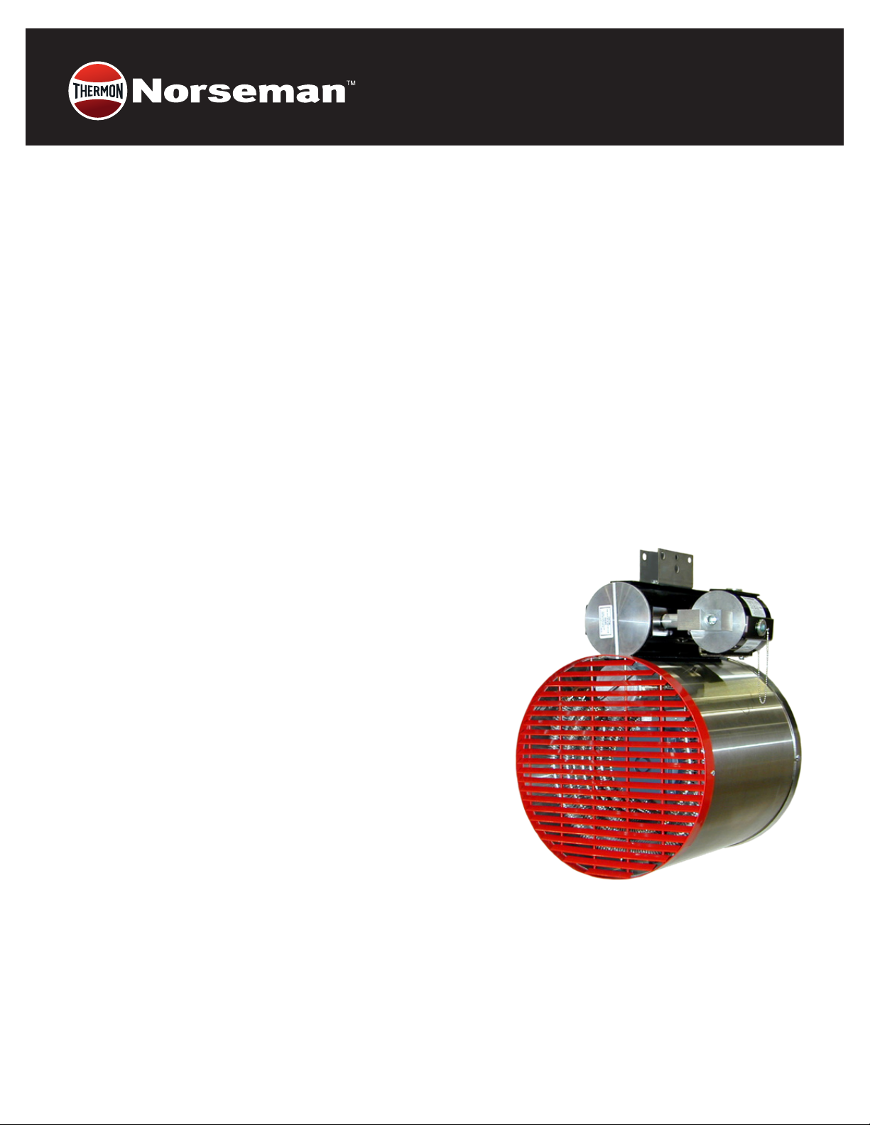
Part No. 11110.Rev.1.04 janv 2021 Imprimé au Canada
XGB Series
Unités de chauage antidéagrantes
Instructions d’installation, d’utilisation et d’entretien
La conception sans glycol

A. Renseignements généraux 15
A.1 Description .........................................................................................................................................15
A.2 Application ........................................................................................................................................15
A.3 Composition et installation....................................................................................................15
A.4 Caractéristiques standard......................................................................................................15
A.5 Options.................................................................................................................................................15
A.6 Thermostats .....................................................................................................................................15
A.7 Moteurs ................................................................................................................................................15
A.8 Accessoires....................................................................................................................................... 16
B. Avant l’installation 17
C. Installation et montage 17
C.1 Dimensions ....................................................................................................................................... 17
C.2 Montage ............................................................................................................................................. 17
C.3 Montage avec les trousses de série ................................................................................ 18
F.6 Auvents de sortie......................................................................................................................... 20
F.7 Cablâge............................................................................................................................................... 20
Table des matières

15
Renseignements généraux
A. RENSEIGNEMENTS GÉNÉRAUX
A.1 Description
Les unités à petit cabinet sont offertes en versions 3,75 à 10 kW, et
sont identiables de par leur moteur interne. Les unités à grand
cabinet, sont offertes en versions 10 à 35 kW. Reportez-vous à
la section C.1 Dimensions, page17 pour les dimensions des
cabinets.
A.2 Application
Conçus tout particulièrement pour le chauffage de zones
industrielles où peuvent se trouver des substances possiblement
explosives. Les environnements dangereux comprennent :
ࢦStations d’épuration et usines de traitement des eaux usées
ࢦRafneries pétrolières
ࢦStations de compression
ࢦUsines de pâte et papier
ࢦCabinets d’entreposage de peinture
ࢦCimenteries
ࢦMines
A.3 Composition et installation
Les unités de chauffage NorsemanMC de Thermon réchauffent
de manière efcace et sécuritaire, à l’aide d’éléments muraux à
ailettes extra lourds en acier tubulaire.
Dans les structures aux plafonds élevés, il se peut que certaines
unités n’offrent pas la puissance nécessaire an de permettre
aux ux d’air d’atteindre le plancher. La conception sans glycol de
l’unité XGB permet à celle-ci d’être inclinée 30 º sous l’horizontale,
en plus d’offrir une redirection de l’air à 35 º, à l’auvent de sortie.
Pour une ventilation latérale, l’auvent au complet peut être monté
à 90 º.
Le joint installé à l’assemblage offre l’isolation nécessaire entre les
boîtiers d’alimentation et de commande. Pour les applications de
Division 2, Zone 1 et Zone 2, un joint de passage peut ne pas être
nécessaire.
Pour faciliter l’installation, les unités de chauffage
antidéagrantes NorsemanMC XGB offrent le boîtier breveté
x-MaxMD avec chariot de bornier coulissant pour la connexion à
l’alimentation électrique
A.4 Caractéristiques standard
Voir Figure 1 et Figure 2, page16.
ࢦCertié CSA C/US pour les endroits dangereux. Unités à
petit cabinet homologuées classe I, div. 1 et 2, groupe D;
classe II, div. 1 et 2, groupes E, F et G. Unités à grand cabinet
homologuées classe I, div. 1 et 2, groupes C et D; classe II, div. 1
et 2, groupes E, F et G.
Remarque: La classe II et certains groupes atmosphériques
peuvent ne pas être offerts à toutes les cotes kW.
ࢦMarquage par zone
ࢦModèles offerts entre 3,75 et 35 kW
ࢦ208 à 600 V, moteur 1 ou 3 phases
ࢦÉléments muraux à ailettes extra lourds en acier tubulaire
plaqué nickel à basse densité
ࢦConception sans glycol permettant une inclinaison de 30 º
vers le bas
ࢦAuvents pivotables offrant une redirection additionnelle de
l’air de 35 º
ࢦBoîtier x-MaxMD breveté avec chariot coulissant simpliant
l’installation et l’entretien
ࢦBoîtier robuste en acier inoxydable de ca. 16
ࢦBorniers de connexion pour thermostat externe
ࢦLimites doubles élevées de réinitialisation automatique
ࢦContacteurs déclassés, pour une plus longue vie utile
ࢦLe boîtier-connecteur de l’alimentation est isolé, et ne requiert
aucun joint de passage
A.5 Options
ࢦThermostat intégré réglable de l’extérieur
ࢦCommutateur intégré
ࢦConstruction antimoisissure
ࢦInterrupteur « automatique / arrêt / ventilateur seul »
ࢦLampe témoin
ࢦLimite élevée pour la réinitialisation manuelle
A.6 Thermostats
Thermon offre une grande variété de thermostats antidéagrants
convenant à presque tous les besoins. Les unités de chauffage
NorsemanMC sont offertes avec thermostats intégrés à ampoule,
réglables de l’extérieur, en option, pouvant être convertis sur
place au modèle inviolable. Les thermostats à distance sont aussi
offerts au besoin.
A.7 Moteurs
Moteur antidéagrant 1725 tr/min à puissance fractionnaire, avec
roulement à billes à double paroi et protecteur de surcharge
thermique intégré. Les unités à petit cabinet utilisent un moteur
1/12 cv homologué classe I, groupe D et classe II, groupes E, F et G.
Les unités à grand cabinet utilisent un moteur 1/2 hp homologué
classe I, groupes C et D et classe II, groupes E, F et G, en formule
standard.

16
Renseignements généraux
A.8 Accessoires
Les unités de chauffage antidéagrantes NorsemanMC s’adaptent
facilement à la plupart des besoins en matière de montage.
Chaque unité de chauffage est équipée d’un support de xation
pivotant compatible avec la plupart des trousses de montage en
option.
Les trousses de montage en option permettent d’installer l’unité
sur les plafonds muraux, les tuyaux de 3 po ou les supports au
sol. Les différentes congurations offrent la plus grande exibilité
possible pour chaque direction de circulation. Le support de
xation pivotant (en série pour toutes les unités de chauffage)
comprend des trous de xation pour une chaîne de sécurité.
Edmonton Head Office & Factory
5918 Roper Road, Edmonton, Alberta, Canada T6B 3E1
P 780.466.3178 F 780.468.5904 Toll Free 1.800.661.8529
Part No. 11110 - Rev. 01
Installation, Operation & Maintenance Instructions for
NorsemanTM XGB Explosion-Proof Unit Heater
3.75 - 35kW, 60 Hz Units
1.0 GENERAL INFORMATION
DESCRIPTION
CCI Thermal’s XGB explosion-proof unit heater is the latest addition
to the NORSEMAN™ line of hazardous location heating products.
The small cabinet units are available with ratings from 3.75 – 10kW,
and can be identified by their internally mounted motor. The large
cabinet units (shown below) are available from 10kW up to 35kW.
See section 3.1 for cabinet dimensions.
APPLICATION
Designed specifically for heating industrial spaces where potentially
explosive substances are or may be present. Typical hazardous
location environments include:
• Water and Sewage Treatment Plants
• Oil Refineries
• Compressor Stations
• Pulp and Paper Mills
• Paint Storage Booths
• Cement Plants
• Mines
CONSTUCTION AND INSTALLATION
CCI Thermal’s NORSEMAN™ unit heaters use extra heavy wall
finned tubular steel heating elements to provide safe, efficient heat
transfer to the environment. The heater does not contain glycol,
decreasing maintenance costs.
Flow adjustment… in structures with high ceilings, other units may
not have the range of motion needed to direct air flow to the floor.
The glycol-free design of the XGB allows the unit to be tilted to a 30º
angle below the horizontal, with an additional 35º of airflow
redirection provided by the outlet louver. For lateral airflow, the entire
louver assembly can be rotated 90º.
No conduit seal required… a factory installed conduit seal
provides the necessary isolation between the supply and control
housings. In Division 2, Zone 1 and Zone 2 applications, a field
installed conduit seal may not be required.
Simplified wiring… to facilitate installation, the NORSEMAN™
explosion-proof unit heaters feature the patented x-Max® housing
with slide out terminal block trolley for connection of the electrical
supply.
STANDARD PRODUCT FEATURES
• CSA C/US Certified for hazardous locations. Small cabinet units
approved for Class I, Div 1 & 2, Group D; Class II, Div. 1 & 2,
Groups E, F and G. Large cabinet units approved for Class I, Div. 1
& 2, Groups C & D; Class II, Div. 1 & 2, Groups E, F & G.
Note: Class II and some atmospheric groups are not available in
every kW rating.
• Optional Zone marking available.
• Ratings from 3.75 – 35kW.
• 208 – 600V, 1 or 3 phase
• Low watt density extra heavy wall tubular steel finned heating
elements with nickel plated finish
• Glycol-free design allows the heater to be tilted 30º downward
• Rotatable outlet louvers provide 35º of additional airflow redirection
• Patented x-Max® housing with track and trolley system simplifies
installation and servicing
• Heavy duty 16 ga. Stainless steel casing
• Terminals for remote thermostat connection
• Dual automatic reset high limits
• Contactor derated for extended service life
• Isolated supply connection housing eliminates the need for conduit
seals
OPTIONAL FEATURES
• Built-in, externally adjustable thermostat
• Built-in disconnect
• Moisture-resistant construction
• “Auto/off/fan-only” switch
• Pilot light
• Manual reset high limit
THERMOSTATS
CCI Thermal offers a wide variety of explosion-proof thermostats to
suit most every need. NORSEMAN™ unit heaters are available with
optional built-in, externally adjustable, bulb type thermostats which
are field-convertible to tamper-proof. Thermostats for remote
mounting can also be provided on request.
MOTORS
Fractional horsepower, 1725 rpm explosion-proof motor with double
shielded ball bearings and built-in thermal overload. Small cabinet
units use 1/12 hp motor approved for Class I, Group D; Class II,
Group E, F, and G. Large cabinet units use 1/2 hp motor approved
for Class I, Groups C and D; Class II, Groups E, F & G, as standard.
ACCESSORIES
NORSEMAN™explosion-proof unit heaters readily adapt to most
mounting requirements. Each heater is equipped with a basic swivel
bracket that is compatible with any of the optional mounting kits.
Optional mounting kits allow the unit to be installed on a wall ceiling,
3” pipe, or floor stand. Each mounting configuration provides
maximum flexibility for outlet flow direction. The swivel bracket Figure 2 - XGB Heater Dimensions
2.0 PRE-INSTALLATION
2.1 Inspect the heater for possible damage due to shipping and
handling. Claims for shipping damages shall be placed with the
carrier.
2.2 Check the heater nameplate to ensure that the heater area
classification and temperature code are suitable for the hazardous
area classification.
2.3 Verify that the nameplate voltage, phase and wattage are as
ordered and are the same as the electrical power supply available.
DO NOT CONNECT THE XGB UNIT HEATER TO A SUPPLY
VOLTAGE OTHER THAN THAT SHOWN ON THE PRODUCT
NAMEPLATE.
3.0 INSTALLATION AND MOUNTING
The heater must be installed by qualified personnel in strict
compliance with the electrical code.
3.1 DIMENSIONS
Table 1: Dimensions and Weights (See Fig. 2)
3.2 MOUNTING
3.2.1 NORSEMAN™ explosion-proof unit heaters can be mounted
to a ceiling, wall 3” pipe, or floor stand. Ensure that the mounting
surface is sufficiently strong to support the heater, which, depending
on the model, could weigh up to 185lbs, (84kg). See 3.1 for heater
dimensions and weights.
3.2.2 The heater must be positioned with a minimum 15 cm (6”) side
clearance from all surrounding surfaces and must be mounted at
least 61 cm (24”) from the floor for small cabinet units, or 2440 cm
(96”) from the floor for large cabinet units. It is best to maximize
clearances to allow freedom of rotation. Ensure that airflow into
and out of the unit is not restricted.
3.2.3 All mounting studs, bolts, nuts and other fasteners shall be
secured so that there is no possibility of loosening over prolonged
periods. Periodically inspect at regular intervals and retighten if
necessary.
3.2.4 All standard mounting kits are designed to support the heater
on its centre of gravity and to allow for 30º tilt in the vertical direction
and 360 º rotation in the horizontal. Note that horizontal rotation is
fixed after the ceiling bracket is bolted to its support.
3.2.5 For specific mounting instructions refer to the appropriate
paragraph of section 3.3.
3.2.6 If lifting with slings, take special care not to damage the casing.
3.2.7 For large cabinet units, leave the heater on the shipping skid
and use the skid as a lifting platform to facilitate installation of the
heater.
3.3 MOUNTING WITH STANDARD KITS
3.3.1 CEILING MOUNTING
a) Install the ceiling bracket to the mounting surface with the desired
orientation. Ensure that ‘LINE A” (Figure 3), a line drawn
perpendicular to the bolt holes in the mounting bar, is pointed in the
desired direction of airflow. The ceiling bracket must be secured to
the mounting surface using as many as six (but not less than two)
5/8” fasteners (not provided). Make certain that lockwashers are
used under all nuts or lag bolts.
b) Hoist the heater up to the ceiling bracket. Line up the large centre
hole in the swivel bracket with the large hole in the mounting bar.
c) Insert the 1/2” bolt and loosely secure with nut and washers
provided. Tilt the heater at the desired angle to the horizontal and
secure with the 3/8” bolt. Tighten the 1/2” bolt.
Figure 3 - Ceiling Mounting
3.3.2 WALL MOUNTING
a) Install the ceiling bracket to the wall bracket with the desired
orientation. Ensure that “LINE A” (Figure 4), a line drawn
perpendicular to the bolt holes in the mounting bar, is pointed in the
desired direction of air flow. Secure the wall bracket to the mounting
surface. The wall bracket must be secured to the mounting surface
using as many as six (but not less than four) 5/8” fasteners (not
provided). Make certain that lockwashers are used under all nuts or
lag bolts.
b) Follow steps b) and c) outlined in 3.3.1.
Figure 4 - Wall Mounting
STANDARD FEATURES, SMALL CABINET UNIT:
1) 1/12 hp explosion-proof motor
2) Inlet guard
3) Extra heavy wall tubular steel finned heating elements with
nickel plated finish
4) Patented x-Max® explosion-proof terminal housing
5) 120V control circuit includes:
• Derated magnetic contactor
• Dual automatic reset high limits
• Transformer
6) Heavy duty 16 ga. stainless steel casing
7) Outlet louver assembly
8) Swivel bracket
9) Factory installed conduit seal
10)Supply connection housing
11)Terminal block for supply wiring and thermostat connection
STANDARD FEATURES, LARGE CABINET UNIT:
1) 1/2 hp explosion-proof motor
2) Inlet wire guard
3) Extra heavy wall tubular steel finned heating elements with
nickel plated finish
4) Patented x-Max® explosion-proof terminal housing
5) 120V control circuit includes:
• Derated magnetic contactor
• Dual automatic reset high limits
• Transformer
• Fan delay relay
• Control fuse
6) Heavy duty 16 ga. stainless steel casing
7) Outlet louver assembly
8) Swivel bracket
9) Factory installed conduit seal
10)Supply connection housing
11)Terminal block for supply wiring and thermostat connection
12)Motor mount
13)Motor mount casing
3.3.3 POST MOUNTING
a) Install the ceiling bracket to the wall bracket with the desired
orientation. Ensure that “LINE A” (Figure 5), a line drawn
perpendicular to the bolt holes in the mounting bar, is pointed in the
desired direction of air flow. Secure the wall bracket to the post using
the 1/2” U-bolts, nuts and washers supplied. Make certain the
lockwashers are used under all nuts or lag bolts.
b) Follow steps b) and c) outlined in 3.3.1.
Figure 5 - Post Mounting
3.3.4 FLOOR STAND MOUNTING
a) At times adequate support for the heater may not be available
within the structure of the space to be heated. In this situation, the
floor mount stand may be desirable. Telescoping square tubing on a
support base allows the unit to be positioned at the desired height
above the floor anywhere between 1.8 m (6’) to 3 m (10’).
b) Position the base of the stand on the floor in the desired
orientation. Ensure that “LINE A” (Figure 6), a line drawn
perpendicular to the bolt holes in the mounting bar, is pointed in the
desired direction of air flow.
c) Next, the stand is to be lagged to a solid floor to prevent the unit
from toppling. Four 11/16” diameter holes are provided in the base of
the stand for this purpose.
d) Raise the mounting frame to the desired height and secure to the
base using the hardware supplied.
e) Hoist the heater up to the mounting frame.
f) Insert the 1/2” bolt and loosely secure with nut and lockwashers
provided. Tilt the heater at the desired angle to the horizontal and
secure with the 3/8” bolt. Tighten the 1/2” bolt.
Figure 6 - Floor Mounting Stand
3.4 OUTLET LOUVRES
3.4.1 A louvred grill on the heater outlet end is supplied as standard.
The louver assembly may be positioned either horizontally or
vertically for maximum flexibility.
3.4.2 Standard heaters are shipped with the louvers in the horizontal
position. To change the orientation of the louvers to vertical, remove
the three mounting screws securing the louver assembly to the
cabinet and rotate the louver 90º to the desired direction.
3.5 WIRING
CAUTION: Whenever hazardous materials are present, ensure
that the terminal housing covers, plugs, etc., are secured (but
not over-tightened) before powering the heater.
All circuits must be in the open position before removing
junction or terminal box covers.
3.5.1 The heater must be installed by qualified personnel in strict
compliance with the electrical code.
3.5.2 All heaters are factory pre-wired and ready for direct
connections to the power supply leads.
3.5.3 The heater must be individually fused, preferably with Class J
time-delay fuses for maximum safety. Unless stated otherwise in
your local code, fuse size shall be 125% of line current or next size
larger. See Table 2 for recommendations.
3.5.4 Use approved conduit and conduit seals are required by the
code for the hazardous location.
3.5.5 The NORSEMAN™ explosion-proof unit heaters are equipped
with a factory installed conduit seal between the control and supply
housings. In Division 2, Zone 1 and Zone 2 applications, a field
installed conduit seal may not be required.
3.5.6 Supply wiring connections are made by accessing the over of
the side mounted supply connection housing (terminal box). Slide
the control trolley out of the housing just enough to access the
terminal block (Figure 8).
3.5.7 Connect the power leads to terminals marked L1and L2 for
single phase and L1, L2 and L3 for three phaseheaters making certain
to leave some excess wire to ensure that the leads may slide back
into the housing with the trolley. See Figure 9 for control circuit and
Figure 10 for suggested wiring. Exercise care to avoid damage to
wires caused by threads on the housing.
Table 2: Recommended Fuse Sizes
Figure 9A - Small Cabinet XGB Wiring Schematic
Figure 9B - Large Cabinet XGB Wiring Schematic
3.5.8 Connect the ground wire to the ground connection located in
the supply connection housing; once again, making sure that the
wire is sufficiently long to slide back into the housing with the trolley.
See Figure 10.
Figure 10 - Supply Connection
3.5.9 Due to the presence of hazardous materials, ensure that
the terminal housing covers, plugs, etc., are secured (but not
over-tightened) before powering the heater.
4.0 TEMPERATURE CONTROL
4.1 BUILT-IN THERMOSTAT (OPTIONAL)
When specified, the unit comes equipped with a built-in thermostat
pre-wired to all other standard controls. Set the temperature to the
desired operating condition.
4.2 REMOTE THERMOSTAT (OPTIONAL)
Install the XT thermostat in accordance with the instruction sheet
provided. Terminals “T1” and “T2” in the heater supply housing are
provided for connection to the remote thermostat and are pre-wired
to the rest of the control circuit. Remove the jumper wire between
“T1” and “T2” and connect the thermostat to these terminals. (Refer
to Figure 9). Set the temperature to the desired operating condition.
5.0 “AUTO / OFF / FAN-ONLY” SWITCH (OPTIONAL)
If ordered, a factory installed “auto / off / fan-only” switch may be
included on the heater. The “fan-only” feature allows the heater to
cycle in a “heat” mode dictated by the controlling thermostat, even
though the fan is operating continuously.
6.0 NORMAL SEQUENCE OF OPERATION
6.1 The heater must be properly mounted and wired in accordance
with the instructions contained in this manual. The fan blade must be
free to rotate with no obstruction to air inlet or outlet areas.
6.2 Energize the heater at the rated supply voltage.
6.3 Assuming that the thermostat calls for heat, i.e. the thermostat is
set to a higher temperature that ambient:
a) The main contactor will energize the elements and the fan motor.
b) After the inlet air temperature rises to the set point of the
thermostat, the thermostat contacts will open and the main contactor
will de-energize the elements and the fan motor.
Note: The large cabinet XGB incorporates a fan delay feature in both
the “ON” and “OFF” cycles. This is a desirable feature as it allows
the heater to come to temperature before the fan operates (no cold
blasts) and to cool down the “OFF” cycle (longer life for control
components and motor). Delay “ON” is 15 - 40 seconds and delay
“OFF” is 60 -160 seconds.
6.4 The cycle described above will repeat when the ambient
temperature falls below the thermostat set point.
IMPORTANT:
THE PROPER MOTOR/FAN ROTATION, VIEWED FROM THE
REAR OF THE HEATER IS COUNTER CLOCKWISE FOR THE
SMALL CABINET UNITS AND CLOCKWISE FOR THE LARGE
CABINET UNITS, AS INDICATED BY THE FAN ROTATION
LABEL ON THE HEATER. INCORRECT ROTATION OF THE FAN
WILL CAUSE THE HEATER TO OVERHEAT AND CYCLE ON THE
HIGH LIMITS. CONSULT FACTORY IN CASE OF INCORRECT
ROTATION.
7.0 MAINTENANCE
7.1 The NORSEMAN™ explosion-proof unit heaters are designed
and constructed to operate in tough industrial applications with a
minimum of maintenance. However, some routine maintenance is
recommended to extend the life of the heater and its components.
Always disconnect the electrical supply before performing any
maintenance.
7.2 Periodically inspect the heater installation to ensure that all
connections, fittings, plugs, screws, covers, etc. are tight and free of
corrosion.
7.3 Check the inside of the cabinet and around the element fins for
dust build-up and debris, especially after seasonal shutdowns.
Clean with an air blast or vacuum. Ensure that nothing is restricting
the air flow into the unit and that the fan blade is free to rotate.
7.4 MOTOR
The motor supplied with the small cabinet units is approved for Class
1, Group D, Class II, Group E, F & G, T3B temperature code. The
motor supplied with the large cabinet units is approved for Class I,
Group C & D, Class II, Group E, F & G, T3B temperature code. All
motors have internal thermal protection to eliminate motor
overheating.
7.5 FAN BLADE
Visually inspect the fan blade to ensure it is free to rotate and
accidental damage has not occurred. If bent or damaged, a factory
balanced blade should be installed so that the rated airflow is
maintained. A damaged fan blade may not deliver the required
airflow over the elements, resulting in cycling on the high limit which
can significantly reduce the life of the contactor and the high limit.
7.6 HEATER CABINET
The XGB unit heater cabinet is stainless steel for superior corrosion
resistance. We recommend the cabinet be wiped down periodically
using a mild detergent.
7.7 OVERHEAT PROTECTION
In the event of fan failure, motor damage, excessive dust build-up or
restricted inlet airflow, the heater temperature may rise, causing the
limit controls to open, breaking the power supply to the heater. All
units are equipped with two automatic reset high limit controls.
Cycling of the high limits should not be permitted.
Should this occur, the unit should be inspected to determine the
cause of the cycling and the condition should be corrected.
8.0 REPLACEMENT PARTS LIST
The replacement parts list is included for reference only. Due to the
delicate nature of explosion-proof design, XGB unit heaters are not
field serviceable. Should any problem arise, return the unit to the
factory for service by trained personnel.
SMALL CABINET UNITS:
LARGE CABINET UNITS:
A CCI Thermal XTK thermostat kit may be purchased to replace a
broken thermostat. Refer to installation instructions provided with
the kit.
Transformers
High Limits
Motor
Contactor
Fan Blade
208V units
240V units
480V units
600V units
T2C T-Code units
T3A T-Code units
T3B T-Code units
All units
All units
10 & 7.5kW units
5 & 3.75kW units
MO250O
MO250Q
MO250S
MO250V
C12023-11
C12023-10
C12023-10
B14302-01
42CF35AF
C11028-06
C11028-05
Transformers
High Limits
Motors
Contactor
Fan Blade
Control Fuse
208V units
240V units
480V units
600V units
T2C T-Code units
T2D T-Code units
T3A T-Code units
T3B T-Code units
208 - 480V 3Ø units
240V 1Ø units
600V units
All units
All units
All units
EXA50-23
EXA50-25
EXA50-36
EXA50-39
C12023-11
C12023-11
C12023-10
C12023-12
1699
1979
2433
42CF35AF
10873
MDL-0.6
GLYCOL
FREE
DESIGN
TERMINAL BLOCK
Figure 8 - XGB Terminal Block Trolley Figure
SIDE
LOOP
TOP
1 OR 3
Ø
SUPPLY
L3
L2
L1
C
H3
H2
H1
TO HEATING
LOAD
X1
120V T1 T2 HI-LIMITS
X2 C/AUX
C NO MOTOR
REMOVE JUMPER FOR
OPTIONAL THERMOSTAT
C
M
LINE A
CEILING BRACKET
MOUNTING BAR
3/8” Flat Washer, Lock Washer, Nut
1/2” Flat Washer, Lock Washer, Nut
MOUNTING SURFACE
11/16” Dia. Mounting Holes
3/8” bolt
1/2” bolt
SWIVEL MOUNTING BRACKET SWIVEL MOUNTING BRACKET
3” PIPE (NOT INCLUDED)
WALL BRACKET
LINE A
CEILING BRACKET
MOUNTNIG BAR
1/2” U-bolt
1/2” flat washer, lock washer, nut
5/8” flatwasher, lockwasher, nut
1/2” flat washer, lock washer, nut
3/8” flat washer, lock washer, nut
5/8” bolt
1/2” bolt
3/8” bolt MOUNTING FRAME
MOUNTING BAR
3/8” flatwasher, lockwasher, nut
1/2” flatwasher, lockwasher, nut
3/8” Bolt
1/2” Bolt
SWIVEL MOUNTING BRACKET
5/8” Bolt
5/8” flatwasher,
lockwasher, nut
LINE A
MOUNTING SURFACE
11/16” dia. mounting holes
5/8” flatwasher, lockwasher, nut
WALL BRACKET
LINE A
CEILING BRACKET
5/8” Bolt
MOUNTING BAR
3/8” flatwasher, lockwasher, nut
1/2” flatwasher, lockwasher, nut
3/8” Bolt
1/2” Bolt
SWIVEL MOUNTING BRACKET
5/8” Bolt M
H1
H2
H3
TO HEATING
LOAD
REMOVE JUMPER FOR
OPTIONAL THERMOSTAT
120V HI-LIMITS
FD
C
FD
1
3
4
5
X2 T1 T2
3ØONLY
C
3ØONLY
X1
L3 L2 L1
L1
L2
L3
1 OR 3Ø
SUPPLY
AIRFLOW
C
A
B
D1
D2
Figure 1B - Large Cabinet XGB Unit Heater Components
Figure 1A - Small Cabinet XGB Unit Heater Components
Recommended
Catalog Number kW Voltage Max Line Amps Fuse Size
(Amps)
1 Ø 3 Ø 1 Ø 3 Ø
XGB038T3B 3.7 5 208 1 9 1 1 2 5 1 5
240 1 7 1 0 2 5 1 5
480 - 6 - 1 0
600 - 5 - 1 0
XGB050T3B 5 208 2 5 1 5 3 5 2 0
240 2 2 1 3 3 0 2 0
480 - 7 - 1 0
600 - 6 - 1 0
XGB075T3A 7 . 5 208 3 7 2 2 5 0 3 0
240 3 2 1 9 4 0 2 5
480 - 1 0 - 1 5
600 - 8 - 1 0
XGB100T2C 1 0 208 2 9 4 0
240 4 3 2 5 6 0 3 5
480 - 1 3 - 2 0
600 - 1 1 - 1 5
XGB100T3B 1 0 208 - 3 0 - 4 0
240 4 7 2 6 6 0 3 5
480 - 1 3 - 2 0
600 - 1 1 - 1 5
XGB150T3B 1 5 208 - 4 4 - 6 0
240 - 3 8 - 5 0
480 - 1 9 - 2 5
600 - 1 5 - 2 0
XGB200T3B 2 0 480 - 2 5 - 3 5
600 - 2 0 - 2 5
XGB225T3A 22. 5 480 - 2 8 - 3 5
600 - 2 3 - 3 0
XGB250T2D 2 5 480 - 3 1 - 4 0
600 - 2 5 - 3 5
XGB300T2D 3 0 480 - 3 7 - 5 0
600 - 3 0 - 4 0
XGB325T2D 32.5 480 - 4 0 - 5 0
600 - 3 2 - 4 0
XGB350T2C 3 5 480 - 4 3 - 6 0
600 - 3 4 - 4 5
A B C D1 D2 Weight
lbs (kg)
Small16-7/ 8 8-7/ 8 25-3-/16 17-1/ 2 - 100
Cabinet(429)(225)(640)(445)(45)
10-15 kW
Large20-1/ 8 8-7/ 8 29-1/ 4 - 31-1/ 4 145 (66)
Cabinet(511)(225)(743)(794)20-35 kW
185 (84)
Caractéristiques de série, pour l’unité à petit cabinet:
1) Moteur antidéagrant 1/12 cv
2) Crépine d’admission d’air
3) Éléments muraux à ailettes extra lourds en acier tubulaire
plaqué nickel
4) Boîtiers à bornier antidéagrants x-MaxMD brevetés
5) Circuit de commande 120 V à :
–Contacteur magnétique déclassé
–Limites doubles élevées de réinitialisation automatique
–Transformateur
6) Heavy duty 16 ga. stainless steel casing
7) Boîtier robuste en acier inoxydable de ca. 16
8) Auvent de sortie
9) Support de xation pivotant
10) Joints de passage en série
11) Boîtier du bornier d’alimentation
12) Borniers de l’alimentation et du thermostat externe
Figure 1 – Composants de l’unité de chauffage XGB à petit cabinet
Caractéristiques de série, pour l’unité à grand cabinet:
1) Moteur antidéagrant 1/2 cv
2) Crépine d’admission d’air grillagée
3) Éléments muraux à ailettes extra lourds en acier tubulaire
plaqué nickel
4) Boîtiers à bornier antidéagrants x-MaxMD brevetés
5) Circuit de commande 120 V à :
–Contacteur magnétique déclassé
–Limites doubles élevées de réinitialisation
automatique
–Transformateur
–Relais de ventilateur temporisé
–Fusible de commande
6) Boîtier robuste en acier inoxydable de ca. 16
7) Auvent de sortie
8) Support de xation pivotant
9) Joints de passage en série
10) Boîtier connecteur d’alimentation
11) Borniers de connexion pour alimentation et thermostat
externe
12) Support à moteur
13) Boîtier de support à moteur
Edmonton Head Office & Factory
5918 Roper Road, Edmonton, Alberta, Canada T6B 3E1
P 780.466.3178 F 780.468.5904 Toll Free 1.800.661.8529
Part No. 11110 - Rev. 01
Installation, Operation & Maintenance Instructions for
NorsemanTM XGB Explosion-Proof Unit Heater
3.75 - 35kW, 60 Hz Units
1.0 GENERAL INFORMATION
DESCRIPTION
CCI Thermal’s XGB explosion-proof unit heater is the latest addition
to the NORSEMAN™ line of hazardous location heating products.
The small cabinet units are available with ratings from 3.75 – 10kW,
and can be identified by their internally mounted motor. The large
cabinet units (shown below) are available from 10kW up to 35kW.
See section 3.1 for cabinet dimensions.
APPLICATION
Designed specifically for heating industrial spaces where potentially
explosive substances are or may be present. Typical hazardous
location environments include:
• Water and Sewage Treatment Plants
• Oil Refineries
• Compressor Stations
• Pulp and Paper Mills
• Paint Storage Booths
• Cement Plants
• Mines
CONSTUCTION AND INSTALLATION
CCI Thermal’s NORSEMAN™ unit heaters use extra heavy wall
finned tubular steel heating elements to provide safe, efficient heat
transfer to the environment. The heater does not contain glycol,
decreasing maintenance costs.
Flow adjustment… in structures with high ceilings, other units may
not have the range of motion needed to direct air flow to the floor.
The glycol-free design of the XGB allows the unit to be tilted to a 30º
angle below the horizontal, with an additional 35º of airflow
redirection provided by the outlet louver. For lateral airflow, the entire
louver assembly can be rotated 90º.
No conduit seal required… a factory installed conduit seal
provides the necessary isolation between the supply and control
housings. In Division 2, Zone 1 and Zone 2 applications, a field
installed conduit seal may not be required.
Simplified wiring… to facilitate installation, the NORSEMAN™
explosion-proof unit heaters feature the patented x-Max® housing
with slide out terminal block trolley for connection of the electrical
supply.
STANDARD PRODUCT FEATURES
• CSA C/US Certified for hazardous locations. Small cabinet units
approved for Class I, Div 1 & 2, Group D; Class II, Div. 1 & 2,
Groups E, F and G. Large cabinet units approved for Class I, Div. 1
& 2, Groups C & D; Class II, Div. 1 & 2, Groups E, F & G.
Note: Class II and some atmospheric groups are not available in
every kW rating.
• Optional Zone marking available.
• Ratings from 3.75 – 35kW.
• 208 – 600V, 1 or 3 phase
• Low watt density extra heavy wall tubular steel finned heating
elements with nickel plated finish
• Glycol-free design allows the heater to be tilted 30º downward
• Rotatable outlet louvers provide 35º of additional airflow redirection
• Patented x-Max® housing with track and trolley system simplifies
installation and servicing
• Heavy duty 16 ga. Stainless steel casing
• Terminals for remote thermostat connection
• Dual automatic reset high limits
• Contactor derated for extended service life
• Isolated supply connection housing eliminates the need for conduit
seals
OPTIONAL FEATURES
• Built-in, externally adjustable thermostat
• Built-in disconnect
• Moisture-resistant construction
• “Auto/off/fan-only” switch
• Pilot light
• Manual reset high limit
THERMOSTATS
CCI Thermal offers a wide variety of explosion-proof thermostats to
suit most every need. NORSEMAN™ unit heaters are available with
optional built-in, externally adjustable, bulb type thermostats which
are field-convertible to tamper-proof. Thermostats for remote
mounting can also be provided on request.
MOTORS
Fractional horsepower, 1725 rpm explosion-proof motor with double
shielded ball bearings and built-in thermal overload. Small cabinet
units use 1/12 hp motor approved for Class I, Group D; Class II,
Group E, F, and G. Large cabinet units use 1/2 hp motor approved
for Class I, Groups C and D; Class II, Groups E, F & G, as standard.
ACCESSORIES
NORSEMAN™explosion-proof unit heaters readily adapt to most
mounting requirements. Each heater is equipped with a basic swivel
bracket that is compatible with any of the optional mounting kits.
Optional mounting kits allow the unit to be installed on a wall ceiling,
3” pipe, or floor stand. Each mounting configuration provides
maximum flexibility for outlet flow direction. The swivel bracket Figure 2 - XGB Heater Dimensions
2.0 PRE-INSTALLATION
2.1 Inspect the heater for possible damage due to shipping and
handling. Claims for shipping damages shall be placed with the
carrier.
2.2 Check the heater nameplate to ensure that the heater area
classification and temperature code are suitable for the hazardous
area classification.
2.3 Verify that the nameplate voltage, phase and wattage are as
ordered and are the same as the electrical power supply available.
DO NOT CONNECT THE XGB UNIT HEATER TO A SUPPLY
VOLTAGE OTHER THAN THAT SHOWN ON THE PRODUCT
NAMEPLATE.
3.0 INSTALLATION AND MOUNTING
The heater must be installed by qualified personnel in strict
compliance with the electrical code.
3.1 DIMENSIONS
Table 1: Dimensions and Weights (See Fig. 2)
3.2 MOUNTING
3.2.1 NORSEMAN™ explosion-proof unit heaters can be mounted
to a ceiling, wall 3” pipe, or floor stand. Ensure that the mounting
surface is sufficiently strong to support the heater, which, depending
on the model, could weigh up to 185lbs, (84kg). See 3.1 for heater
dimensions and weights.
3.2.2 The heater must be positioned with a minimum 15 cm (6”) side
clearance from all surrounding surfaces and must be mounted at
least 61 cm (24”) from the floor for small cabinet units, or 2440 cm
(96”) from the floor for large cabinet units. It is best to maximize
clearances to allow freedom of rotation. Ensure that airflow into
and out of the unit is not restricted.
3.2.3 All mounting studs, bolts, nuts and other fasteners shall be
secured so that there is no possibility of loosening over prolonged
periods. Periodically inspect at regular intervals and retighten if
necessary.
3.2.4 All standard mounting kits are designed to support the heater
on its centre of gravity and to allow for 30º tilt in the vertical direction
and 360 º rotation in the horizontal. Note that horizontal rotation is
fixed after the ceiling bracket is bolted to its support.
3.2.5 For specific mounting instructions refer to the appropriate
paragraph of section 3.3.
3.2.6 If lifting with slings, take special care not to damage the casing.
3.2.7 For large cabinet units, leave the heater on the shipping skid
and use the skid as a lifting platform to facilitate installation of the
heater.
3.3 MOUNTING WITH STANDARD KITS
3.3.1 CEILING MOUNTING
a) Install the ceiling bracket to the mounting surface with the desired
orientation. Ensure that ‘LINE A” (Figure 3), a line drawn
perpendicular to the bolt holes in the mounting bar, is pointed in the
desired direction of airflow. The ceiling bracket must be secured to
the mounting surface using as many as six (but not less than two)
5/8” fasteners (not provided). Make certain that lockwashers are
used under all nuts or lag bolts.
b) Hoist the heater up to the ceiling bracket. Line up the large centre
hole in the swivel bracket with the large hole in the mounting bar.
c) Insert the 1/2” bolt and loosely secure with nut and washers
provided. Tilt the heater at the desired angle to the horizontal and
secure with the 3/8” bolt. Tighten the 1/2” bolt.
Figure 3 - Ceiling Mounting
3.3.2 WALL MOUNTING
a) Install the ceiling bracket to the wall bracket with the desired
orientation. Ensure that “LINE A” (Figure 4), a line drawn
perpendicular to the bolt holes in the mounting bar, is pointed in the
desired direction of air flow. Secure the wall bracket to the mounting
surface. The wall bracket must be secured to the mounting surface
using as many as six (but not less than four) 5/8” fasteners (not
provided). Make certain that lockwashers are used under all nuts or
lag bolts.
b) Follow steps b) and c) outlined in 3.3.1.
Figure 4 - Wall Mounting
STANDARD FEATURES, SMALL CABINET UNIT:
1) 1/12 hp explosion-proof motor
2) Inlet guard
3) Extra heavy wall tubular steel finned heating elements with
nickel plated finish
4) Patented x-Max® explosion-proof terminal housing
5) 120V control circuit includes:
• Derated magnetic contactor
• Dual automatic reset high limits
• Transformer
6) Heavy duty 16 ga. stainless steel casing
7) Outlet louver assembly
8) Swivel bracket
9) Factory installed conduit seal
10)Supply connection housing
11)Terminal block for supply wiring and thermostat connection
STANDARD FEATURES, LARGE CABINET UNIT:
1) 1/2 hp explosion-proof motor
2) Inlet wire guard
3) Extra heavy wall tubular steel finned heating elements with
nickel plated finish
4) Patented x-Max® explosion-proof terminal housing
5) 120V control circuit includes:
• Derated magnetic contactor
• Dual automatic reset high limits
• Transformer
• Fan delay relay
• Control fuse
6) Heavy duty 16 ga. stainless steel casing
7) Outlet louver assembly
8) Swivel bracket
9) Factory installed conduit seal
10)Supply connection housing
11)Terminal block for supply wiring and thermostat connection
12)Motor mount
13)Motor mount casing
3.3.3 POST MOUNTING
a) Install the ceiling bracket to the wall bracket with the desired
orientation. Ensure that “LINE A” (Figure 5), a line drawn
perpendicular to the bolt holes in the mounting bar, is pointed in the
desired direction of air flow. Secure the wall bracket to the post using
the 1/2” U-bolts, nuts and washers supplied. Make certain the
lockwashers are used under all nuts or lag bolts.
b) Follow steps b) and c) outlined in 3.3.1.
Figure 5 - Post Mounting
3.3.4 FLOOR STAND MOUNTING
a) At times adequate support for the heater may not be available
within the structure of the space to be heated. In this situation, the
floor mount stand may be desirable. Telescoping square tubing on a
support base allows the unit to be positioned at the desired height
above the floor anywhere between 1.8 m (6’) to 3 m (10’).
b) Position the base of the stand on the floor in the desired
orientation. Ensure that “LINE A” (Figure 6), a line drawn
perpendicular to the bolt holes in the mounting bar, is pointed in the
desired direction of air flow.
c) Next, the stand is to be lagged to a solid floor to prevent the unit
from toppling. Four 11/16” diameter holes are provided in the base of
the stand for this purpose.
d) Raise the mounting frame to the desired height and secure to the
base using the hardware supplied.
e) Hoist the heater up to the mounting frame.
f) Insert the 1/2” bolt and loosely secure with nut and lockwashers
provided. Tilt the heater at the desired angle to the horizontal and
secure with the 3/8” bolt. Tighten the 1/2” bolt.
Figure 6 - Floor Mounting Stand
3.4 OUTLET LOUVRES
3.4.1 A louvred grill on the heater outlet end is supplied as standard.
The louver assembly may be positioned either horizontally or
vertically for maximum flexibility.
3.4.2 Standard heaters are shipped with the louvers in the horizontal
position. To change the orientation of the louvers to vertical, remove
the three mounting screws securing the louver assembly to the
cabinet and rotate the louver 90º to the desired direction.
3.5 WIRING
CAUTION: Whenever hazardous materials are present, ensure
that the terminal housing covers, plugs, etc., are secured (but
not over-tightened) before powering the heater.
All circuits must be in the open position before removing
junction or terminal box covers.
3.5.1 The heater must be installed by qualified personnel in strict
compliance with the electrical code.
3.5.2 All heaters are factory pre-wired and ready for direct
connections to the power supply leads.
3.5.3 The heater must be individually fused, preferably with Class J
time-delay fuses for maximum safety. Unless stated otherwise in
your local code, fuse size shall be 125% of line current or next size
larger. See Table 2 for recommendations.
3.5.4 Use approved conduit and conduit seals are required by the
code for the hazardous location.
3.5.5 The NORSEMAN™ explosion-proof unit heaters are equipped
with a factory installed conduit seal between the control and supply
housings. In Division 2, Zone 1 and Zone 2 applications, a field
installed conduit seal may not be required.
3.5.6 Supply wiring connections are made by accessing the over of
the side mounted supply connection housing (terminal box). Slide
the control trolley out of the housing just enough to access the
terminal block (Figure 8).
3.5.7 Connect the power leads to terminals marked L1and L2 for
single phase and L1, L2 and L3 for three phaseheaters making certain
to leave some excess wire to ensure that the leads may slide back
into the housing with the trolley. See Figure 9 for control circuit and
Figure 10 for suggested wiring. Exercise care to avoid damage to
wires caused by threads on the housing.
Table 2: Recommended Fuse Sizes
Figure 9A - Small Cabinet XGB Wiring Schematic
Figure 9B - Large Cabinet XGB Wiring Schematic
3.5.8 Connect the ground wire to the ground connection located in
the supply connection housing; once again, making sure that the
wire is sufficiently long to slide back into the housing with the trolley.
See Figure 10.
Figure 10 - Supply Connection
3.5.9 Due to the presence of hazardous materials, ensure that
the terminal housing covers, plugs, etc., are secured (but not
over-tightened) before powering the heater.
4.0 TEMPERATURE CONTROL
4.1 BUILT-IN THERMOSTAT (OPTIONAL)
When specified, the unit comes equipped with a built-in thermostat
pre-wired to all other standard controls. Set the temperature to the
desired operating condition.
4.2 REMOTE THERMOSTAT (OPTIONAL)
Install the XT thermostat in accordance with the instruction sheet
provided. Terminals “T1” and “T2” in the heater supply housing are
provided for connection to the remote thermostat and are pre-wired
to the rest of the control circuit. Remove the jumper wire between
“T1” and “T2” and connect the thermostat to these terminals. (Refer
to Figure 9). Set the temperature to the desired operating condition.
5.0 “AUTO / OFF / FAN-ONLY” SWITCH (OPTIONAL)
If ordered, a factory installed “auto / off / fan-only” switch may be
included on the heater. The “fan-only” feature allows the heater to
cycle in a “heat” mode dictated by the controlling thermostat, even
though the fan is operating continuously.
6.0 NORMAL SEQUENCE OF OPERATION
6.1 The heater must be properly mounted and wired in accordance
with the instructions contained in this manual. The fan blade must be
free to rotate with no obstruction to air inlet or outlet areas.
6.2 Energize the heater at the rated supply voltage.
6.3 Assuming that the thermostat calls for heat, i.e. the thermostat is
set to a higher temperature that ambient:
a) The main contactor will energize the elements and the fan motor.
b) After the inlet air temperature rises to the set point of the
thermostat, the thermostat contacts will open and the main contactor
will de-energize the elements and the fan motor.
Note: The large cabinet XGB incorporates a fan delay feature in both
the “ON” and “OFF” cycles. This is a desirable feature as it allows
the heater to come to temperature before the fan operates (no cold
blasts) and to cool down the “OFF” cycle (longer life for control
components and motor). Delay “ON” is 15 - 40 seconds and delay
“OFF” is 60 -160 seconds.
6.4 The cycle described above will repeat when the ambient
temperature falls below the thermostat set point.
IMPORTANT:
THE PROPER MOTOR/FAN ROTATION, VIEWED FROM THE
REAR OF THE HEATER IS COUNTER CLOCKWISE FOR THE
SMALL CABINET UNITS AND CLOCKWISE FOR THE LARGE
CABINET UNITS, AS INDICATED BY THE FAN ROTATION
LABEL ON THE HEATER. INCORRECT ROTATION OF THE FAN
WILL CAUSE THE HEATER TO OVERHEAT AND CYCLE ON THE
HIGH LIMITS. CONSULT FACTORY IN CASE OF INCORRECT
ROTATION.
7.0 MAINTENANCE
7.1 The NORSEMAN™ explosion-proof unit heaters are designed
and constructed to operate in tough industrial applications with a
minimum of maintenance. However, some routine maintenance is
recommended to extend the life of the heater and its components.
Always disconnect the electrical supply before performing any
maintenance.
7.2 Periodically inspect the heater installation to ensure that all
connections, fittings, plugs, screws, covers, etc. are tight and free of
corrosion.
7.3 Check the inside of the cabinet and around the element fins for
dust build-up and debris, especially after seasonal shutdowns.
Clean with an air blast or vacuum. Ensure that nothing is restricting
the air flow into the unit and that the fan blade is free to rotate.
7.4 MOTOR
The motor supplied with the small cabinet units is approved for Class
1, Group D, Class II, Group E, F & G, T3B temperature code. The
motor supplied with the large cabinet units is approved for Class I,
Group C & D, Class II, Group E, F & G, T3B temperature code. All
motors have internal thermal protection to eliminate motor
overheating.
7.5 FAN BLADE
Visually inspect the fan blade to ensure it is free to rotate and
accidental damage has not occurred. If bent or damaged, a factory
balanced blade should be installed so that the rated airflow is
maintained. A damaged fan blade may not deliver the required
airflow over the elements, resulting in cycling on the high limit which
can significantly reduce the life of the contactor and the high limit.
7.6 HEATER CABINET
The XGB unit heater cabinet is stainless steel for superior corrosion
resistance. We recommend the cabinet be wiped down periodically
using a mild detergent.
7.7 OVERHEAT PROTECTION
In the event of fan failure, motor damage, excessive dust build-up or
restricted inlet airflow, the heater temperature may rise, causing the
limit controls to open, breaking the power supply to the heater. All
units are equipped with two automatic reset high limit controls.
Cycling of the high limits should not be permitted.
Should this occur, the unit should be inspected to determine the
cause of the cycling and the condition should be corrected.
8.0 REPLACEMENT PARTS LIST
The replacement parts list is included for reference only. Due to the
delicate nature of explosion-proof design, XGB unit heaters are not
field serviceable. Should any problem arise, return the unit to the
factory for service by trained personnel.
SMALL CABINET UNITS:
LARGE CABINET UNITS:
A CCI Thermal XTK thermostat kit may be purchased to replace a
broken thermostat. Refer to installation instructions provided with
the kit.
Transformers
High Limits
Motor
Contactor
Fan Blade
208V units
240V units
480V units
600V units
T2C T-Code units
T3A T-Code units
T3B T-Code units
All units
All units
10 & 7.5kW units
5 & 3.75kW units
MO250O
MO250Q
MO250S
MO250V
C12023-11
C12023-10
C12023-10
B14302-01
42CF35AF
C11028-06
C11028-05
Transformers
High Limits
Motors
Contactor
Fan Blade
Control Fuse
208V units
240V units
480V units
600V units
T2C T-Code units
T2D T-Code units
T3A T-Code units
T3B T-Code units
208 - 480V 3Ø units
240V 1Ø units
600V units
All units
All units
All units
EXA50-23
EXA50-25
EXA50-36
EXA50-39
C12023-11
C12023-11
C12023-10
C12023-12
1699
1979
2433
42CF35AF
10873
MDL-0.6
GLYCOL
FREE
DESIGN
TERMINAL BLOCK
Figure 8 - XGB Terminal Block Trolley Figure
SIDE
LOOP
TOP
1 OR 3
Ø
SUPPLY
L3
L2
L1
C
H3
H2
H1
TO HEATING
LOAD
X1
120V T1 T2 HI-LIMITS
X2 C/AUX
C NO MOTOR
REMOVE JUMPER FOR
OPTIONAL THERMOSTAT
C
M
LINE A
CEILING BRACKET
MOUNTING BAR
3/8” Flat Washer, Lock Washer, Nut
1/2” Flat Washer, Lock Washer, Nut
MOUNTING SURFACE
11/16” Dia. Mounting Holes
3/8” bolt
1/2” bolt
SWIVEL MOUNTING BRACKET SWIVEL MOUNTING BRACKET
3” PIPE (NOT INCLUDED)
WALL BRACKET
LINE A
CEILING BRACKET
MOUNTNIG BAR
1/2” U-bolt
1/2” flat washer, lock washer, nut
5/8” flatwasher, lockwasher, nut
1/2” flat washer, lock washer, nut
3/8” flat washer, lock washer, nut
5/8” bolt
1/2” bolt
3/8” bolt MOUNTING FRAME
MOUNTING BAR
3/8” flatwasher, lockwasher, nut
1/2” flatwasher, lockwasher, nut
3/8” Bolt
1/2” Bolt
SWIVEL MOUNTING BRACKET
5/8” Bolt
5/8” flatwasher,
lockwasher, nut
LINE A
MOUNTING SURFACE
11/16” dia. mounting holes
5/8” flatwasher, lockwasher, nut
WALL BRACKET
LINE A
CEILING BRACKET
5/8” Bolt
MOUNTING BAR
3/8” flatwasher, lockwasher, nut
1/2” flatwasher, lockwasher, nut
3/8” Bolt
1/2” Bolt
SWIVEL MOUNTING BRACKET
5/8” Bolt M
H1
H2
H3
TO HEATING
LOAD
REMOVE JUMPER FOR
OPTIONAL THERMOSTAT
120V HI-LIMITS
FD
C
FD
1
3
4
5
X2 T1 T2
3ØONLY
C
3ØONLY
X1
L3 L2 L1
L1
L2
L3
1 OR 3Ø
SUPPLY
AIRFLOW
C
A
B
D1
D2
Figure 1B - Large Cabinet XGB Unit Heater Components
Figure 1A - Small Cabinet XGB Unit Heater Components
Recommended
Catalog Number kW Voltage Max Line Amps Fuse Size
(Amps)
1 Ø 3 Ø 1 Ø 3 Ø
XGB038T3B 3. 7 5 208 1 9 1 1 2 5 1 5
240 1 7 1 0 2 5 1 5
480 - 6 - 1 0
600 - 5 - 1 0
XGB050T3B 5 208 2 5 1 5 3 5 2 0
240 2 2 1 3 3 0 2 0
480 - 7 - 1 0
600 - 6 - 1 0
XGB075T3A 7 . 5 208 3 7 2 2 5 0 3 0
240 3 2 1 9 4 0 2 5
480 - 1 0 - 1 5
600 - 8 - 1 0
XGB100T2C 1 0 208 2 9 4 0
240 4 3 2 5 6 0 3 5
480 - 1 3 - 2 0
600 - 1 1 - 1 5
XGB100T3B 1 0 208 - 3 0 - 4 0
240 4 7 2 6 6 0 3 5
480 - 1 3 - 2 0
600 - 1 1 - 1 5
XGB150T3B 1 5 208 - 4 4 - 6 0
240 - 3 8 - 5 0
480 - 1 9 - 2 5
600 - 1 5 - 2 0
XGB200T3B 2 0 480 - 2 5 - 3 5
600 - 2 0 - 2 5
XGB225T3A 22. 5 480 - 2 8 - 3 5
600 - 2 3 - 3 0
XGB250T2D 2 5 480 - 3 1 - 4 0
600 - 2 5 - 3 5
XGB300T2D 3 0 480 - 3 7 - 5 0
600 - 3 0 - 4 0
XGB325T2D 32.5 480 - 4 0 - 5 0
600 - 3 2 - 4 0
XGB350T2C 3 5 480 - 4 3 - 6 0
600 - 3 4 - 4 5
A B C D1 D2 Weight
lbs (kg)
Small16-7/ 8 8-7/ 8 25-3-/ 16 17-1/ 2 - 100
Cabinet(429)(225)(640)(445)(45)
10-15 kW
Large20-1/ 8 8-7/ 8 29-1/ 4 - 31-1/ 4 145 (66)
Cabinet(511)(225)(743)(794)20-35 kW
185 (84)
Figure 2 – Composants de l’unité de chauffage XGB à grand cabinet
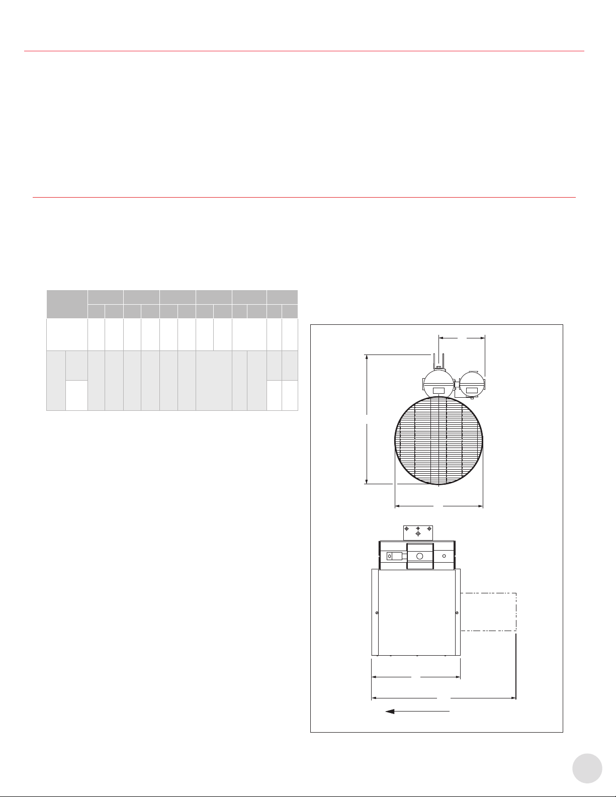
17
Avant l’installation
B. AVANT L’INSTALLATION
1. Inspecter le radiateur an de repérer d’éventuels
dommages causés par le transport et la manutention.
Les réclamations pour les dommages causés par le
transport doivent être déposées auprès du transporteur.
2. Vérier la plaque signalétique du radiateur an de
conrmer que la classication de zone et le code de
température du radiateur sont adaptés à la classication
de la zone dangereuse.
3. Vérier que la tension, la phase et le wattage sur
la plaque signalétique correspondent aux valeurs
commandées, et qu’elles conviennent à l’alimentation
disponible. NE PAS BRANCHER LE RADIATEUR DANS
UNE ALIMENTATION ÉLECTRIQUE D’UNE TENSION
AUTRE QUE CELLE INDIQUÉE SUR LA PLAQUE
SIGNALÉTIQUE DU PRODUIT.
C. INSTALLATION ET MONTAGE
L’appareil de chauffage doit être installé par un personnel qualié
se conformant strictement aux codes de l’électricité.
C.1 Dimensions
Tableau 1 – Dimensions et poids (Figure 3, page17)
Type
d’armoire
A B C D1 D2 Poids
po mm po mm po mm po mm po mm lb kg
Petit 16
7/8 429 8
7/8 225 25
3/16 640 17
1/2 445 –100 45
Grand
10-15
kW
20
1/8 511 8
7/8 225 29
1/4 743 –31
1/4 794
145 66
20-35
kW 185 84
C.2 Montage
1. Les unités de chauffage antidéagrantes NorsemanMC
peuvent être installées sur les plafonds muraux, les
tuyaux de 3 po ou les supports au sol. Conrmer que
la cloison de l’enceinte est sufsamment solide pour
soutenir l’unité de chauffage dont le poids, selon le
modèle, peut atteindre 84 kg (185 lb). Assurer assez de
robustesse de manière à prévenir la vibration excessive
et résister aux situations les plus difciles, comme les
installations transportables. Reportez-vous à la section C.1
Dimensions, page17 pour les dimensions et poids.
2. L’unité de chauffage doit être positionnée à 15 cm
(6 po) d’espace, au minimum, de toutes les surfaces
environnantes, et montée au moins à 61 cm (24 po) du
plancher, pour les petits cabinets, ou 2440 cm (96 po),
pour les grands cabinets. Il est recommandé de prévoir le
plus grand espace possible, pour permettre une grande
liberté de rotation. Assurer que les circulations entrante
et sortante ne sont pas bloquées.
3. Les tourillons, boulons, écrous et autres xations de
montage doivent être serrés de manière à empêcher
le dévissage sur de longues périodes. Les inspecter
régulièrement et les resserrer au besoin.
4. Toutes les trousses de montage sont conçues pour
soutenir l’unité de chauffage à son centre de gravité
et permettre une inclinaison verticale de 30 º et une
rotation horizontale de 360 º. Remarquez que la rotation
horizontale est xée si le support de xation supérieur
est vissé.
5. Les instructions de montage particulières sont dénies
au paragraphe pertinent de la section C.3 Montage avec
les trousses de série, page18.
6. Si l’unité est soulevée à l’aide de courroies, faire
particulièrement attention de ne pas endommager le
boîtier.
7. Laisser les unités de chauffage à grand cabinet sur la
palette de livraison, et utiliser celle-ci comme plateforme
de levage pour faciliter l’installation.
AIRFLOW
C
A
B
D1
D2
Circulation d’air
Figure 3 – Dimensions de l’unité de chauffage

18
Installation et montage
C.3 Montage avec les trousses de série
1. Montage au plafond
1.1 Installer le support de xation sur la surface de
montage avec l’orientation préférée. Assurer
que la « LIGNE A » (Figure 4, page18), la ligne
perpendiculaire entre les trous de boulonnage de
la barre de xation, sont pointées dans le sens de
circulation préféré. Le support plafonnier doit être
xé à la surface de montage avec, tout au plus, six
(mais non moins de deux) attaches 5/8 po (non
comprises). Assurez-vous que des rondelles d’arrêt
ou boulons de blocage sont xés à tous les écrous.
1.2 Soulever l’unité de chauffage vers le support
plafonnier. Aligner le trou central du support
pivotant au trou correspondant sur la barre de
montage.
1.3 Insérer l’écrou de 1/2 po et visser librement avec
les boulons et rondelles fournis. Incliner l’unité de
chauffage à l’angle horizontal souhaité et xer avec
l’écrou de 3/8 po. Serrer l’écrou de 1/2 po.
Edmonton Head Office & Factory
5918 Roper Road, Edmonton, Alberta, Canada T6B 3E1
P 780.466.3178 F 780.468.5904 Toll Free 1.800.661.8529
Part No. 11110 - Rev. 01
Installation, Operation & Maintenance Instructions for
NorsemanTM XGB Explosion-Proof Unit Heater
3.75 - 35kW, 60 Hz Units
1.0 GENERAL INFORMATION
DESCRIPTION
CCI Thermal’s XGB explosion-proof unit heater is the latest addition
to the NORSEMAN™ line of hazardous location heating products.
The small cabinet units are available with ratings from 3.75 – 10kW,
and can be identified by their internally mounted motor. The large
cabinet units (shown below) are available from 10kW up to 35kW.
See section 3.1 for cabinet dimensions.
APPLICATION
Designed specifically for heating industrial spaces where potentially
explosive substances are or may be present. Typical hazardous
location environments include:
• Water and Sewage Treatment Plants
• Oil Refineries
• Compressor Stations
• Pulp and Paper Mills
• Paint Storage Booths
• Cement Plants
• Mines
CONSTUCTION AND INSTALLATION
CCI Thermal’s NORSEMAN™ unit heaters use extra heavy wall
finned tubular steel heating elements to provide safe, efficient heat
transfer to the environment. The heater does not contain glycol,
decreasing maintenance costs.
Flow adjustment… in structures with high ceilings, other units may
not have the range of motion needed to direct air flow to the floor.
The glycol-free design of the XGB allows the unit to be tilted to a 30º
angle below the horizontal, with an additional 35º of airflow
redirection provided by the outlet louver. For lateral airflow, the entire
louver assembly can be rotated 90º.
No conduit seal required… a factory installed conduit seal
provides the necessary isolation between the supply and control
housings. In Division 2, Zone 1 and Zone 2 applications, a field
installed conduit seal may not be required.
Simplified wiring… to facilitate installation, the NORSEMAN™
explosion-proof unit heaters feature the patented x-Max® housing
with slide out terminal block trolley for connection of the electrical
supply.
STANDARD PRODUCT FEATURES
• CSA C/US Certified for hazardous locations. Small cabinet units
approved for Class I, Div 1 & 2, Group D; Class II, Div. 1 & 2,
Groups E, F and G. Large cabinet units approved for Class I, Div. 1
& 2, Groups C & D; Class II, Div. 1 & 2, Groups E, F & G.
Note: Class II and some atmospheric groups are not available in
every kW rating.
• Optional Zone marking available.
• Ratings from 3.75 – 35kW.
• 208 – 600V, 1 or 3 phase
• Low watt density extra heavy wall tubular steel finned heating
elements with nickel plated finish
• Glycol-free design allows the heater to be tilted 30º downward
• Rotatable outlet louvers provide 35º of additional airflow redirection
• Patented x-Max® housing with track and trolley system simplifies
installation and servicing
• Heavy duty 16 ga. Stainless steel casing
• Terminals for remote thermostat connection
• Dual automatic reset high limits
• Contactor derated for extended service life
• Isolated supply connection housing eliminates the need for conduit
seals
OPTIONAL FEATURES
• Built-in, externally adjustable thermostat
• Built-in disconnect
• Moisture-resistant construction
• “Auto/off/fan-only” switch
• Pilot light
• Manual reset high limit
THERMOSTATS
CCI Thermal offers a wide variety of explosion-proof thermostats to
suit most every need. NORSEMAN™ unit heaters are available with
optional built-in, externally adjustable, bulb type thermostats which
are field-convertible to tamper-proof. Thermostats for remote
mounting can also be provided on request.
MOTORS
Fractional horsepower, 1725 rpm explosion-proof motor with double
shielded ball bearings and built-in thermal overload. Small cabinet
units use 1/12 hp motor approved for Class I, Group D; Class II,
Group E, F, and G. Large cabinet units use 1/2 hp motor approved
for Class I, Groups C and D; Class II, Groups E, F & G, as standard.
ACCESSORIES
NORSEMAN™explosion-proof unit heaters readily adapt to most
mounting requirements. Each heater is equipped with a basic swivel
bracket that is compatible with any of the optional mounting kits.
Optional mounting kits allow the unit to be installed on a wall ceiling,
3” pipe, or floor stand. Each mounting configuration provides
maximum flexibility for outlet flow direction. The swivel bracket Figure 2 - XGB Heater Dimensions
2.0 PRE-INSTALLATION
2.1 Inspect the heater for possible damage due to shipping and
handling. Claims for shipping damages shall be placed with the
carrier.
2.2 Check the heater nameplate to ensure that the heater area
classification and temperature code are suitable for the hazardous
area classification.
2.3 Verify that the nameplate voltage, phase and wattage are as
ordered and are the same as the electrical power supply available.
DO NOT CONNECT THE XGB UNIT HEATER TO A SUPPLY
VOLTAGE OTHER THAN THAT SHOWN ON THE PRODUCT
NAMEPLATE.
3.0 INSTALLATION AND MOUNTING
The heater must be installed by qualified personnel in strict
compliance with the electrical code.
3.1 DIMENSIONS
Table 1: Dimensions and Weights (See Fig. 2)
3.2 MOUNTING
3.2.1 NORSEMAN™ explosion-proof unit heaters can be mounted
to a ceiling, wall 3” pipe, or floor stand. Ensure that the mounting
surface is sufficiently strong to support the heater, which, depending
on the model, could weigh up to 185lbs, (84kg). See 3.1 for heater
dimensions and weights.
3.2.2 The heater must be positioned with a minimum 15 cm (6”) side
clearance from all surrounding surfaces and must be mounted at
least 61 cm (24”) from the floor for small cabinet units, or 2440 cm
(96”) from the floor for large cabinet units. It is best to maximize
clearances to allow freedom of rotation. Ensure that airflow into
and out of the unit is not restricted.
3.2.3 All mounting studs, bolts, nuts and other fasteners shall be
secured so that there is no possibility of loosening over prolonged
periods. Periodically inspect at regular intervals and retighten if
necessary.
3.2.4 All standard mounting kits are designed to support the heater
on its centre of gravity and to allow for 30º tilt in the vertical direction
and 360 º rotation in the horizontal. Note that horizontal rotation is
fixed after the ceiling bracket is bolted to its support.
3.2.5 For specific mounting instructions refer to the appropriate
paragraph of section 3.3.
3.2.6 If lifting with slings, take special care not to damage the casing.
3.2.7 For large cabinet units, leave the heater on the shipping skid
and use the skid as a lifting platform to facilitate installation of the
heater.
3.3 MOUNTING WITH STANDARD KITS
3.3.1 CEILING MOUNTING
a) Install the ceiling bracket to the mounting surface with the desired
orientation. Ensure that ‘LINE A” (Figure 3), a line drawn
perpendicular to the bolt holes in the mounting bar, is pointed in the
desired direction of airflow. The ceiling bracket must be secured to
the mounting surface using as many as six (but not less than two)
5/8” fasteners (not provided). Make certain that lockwashers are
used under all nuts or lag bolts.
b) Hoist the heater up to the ceiling bracket. Line up the large centre
hole in the swivel bracket with the large hole in the mounting bar.
c) Insert the 1/2” bolt and loosely secure with nut and washers
provided. Tilt the heater at the desired angle to the horizontal and
secure with the 3/8” bolt. Tighten the 1/2” bolt.
Figure 3 - Ceiling Mounting
3.3.2 WALL MOUNTING
a) Install the ceiling bracket to the wall bracket with the desired
orientation. Ensure that “LINE A” (Figure 4), a line drawn
perpendicular to the bolt holes in the mounting bar, is pointed in the
desired direction of air flow. Secure the wall bracket to the mounting
surface. The wall bracket must be secured to the mounting surface
using as many as six (but not less than four) 5/8” fasteners (not
provided). Make certain that lockwashers are used under all nuts or
lag bolts.
b) Follow steps b) and c) outlined in 3.3.1.
Figure 4 - Wall Mounting
STANDARD FEATURES, SMALL CABINET UNIT:
1) 1/12 hp explosion-proof motor
2) Inlet guard
3) Extra heavy wall tubular steel finned heating elements with
nickel plated finish
4) Patented x-Max® explosion-proof terminal housing
5) 120V control circuit includes:
• Derated magnetic contactor
• Dual automatic reset high limits
• Transformer
6) Heavy duty 16 ga. stainless steel casing
7) Outlet louver assembly
8) Swivel bracket
9) Factory installed conduit seal
10)Supply connection housing
11)Terminal block for supply wiring and thermostat connection
STANDARD FEATURES, LARGE CABINET UNIT:
1) 1/2 hp explosion-proof motor
2) Inlet wire guard
3) Extra heavy wall tubular steel finned heating elements with
nickel plated finish
4) Patented x-Max® explosion-proof terminal housing
5) 120V control circuit includes:
• Derated magnetic contactor
• Dual automatic reset high limits
• Transformer
• Fan delay relay
• Control fuse
6) Heavy duty 16 ga. stainless steel casing
7) Outlet louver assembly
8) Swivel bracket
9) Factory installed conduit seal
10)Supply connection housing
11)Terminal block for supply wiring and thermostat connection
12)Motor mount
13)Motor mount casing
3.3.3 POST MOUNTING
a) Install the ceiling bracket to the wall bracket with the desired
orientation. Ensure that “LINE A” (Figure 5), a line drawn
perpendicular to the bolt holes in the mounting bar, is pointed in the
desired direction of air flow. Secure the wall bracket to the post using
the 1/2” U-bolts, nuts and washers supplied. Make certain the
lockwashers are used under all nuts or lag bolts.
b) Follow steps b) and c) outlined in 3.3.1.
Figure 5 - Post Mounting
3.3.4 FLOOR STAND MOUNTING
a) At times adequate support for the heater may not be available
within the structure of the space to be heated. In this situation, the
floor mount stand may be desirable. Telescoping square tubing on a
support base allows the unit to be positioned at the desired height
above the floor anywhere between 1.8 m (6’) to 3 m (10’).
b) Position the base of the stand on the floor in the desired
orientation. Ensure that “LINE A” (Figure 6), a line drawn
perpendicular to the bolt holes in the mounting bar, is pointed in the
desired direction of air flow.
c) Next, the stand is to be lagged to a solid floor to prevent the unit
from toppling. Four 11/16” diameter holes are provided in the base of
the stand for this purpose.
d) Raise the mounting frame to the desired height and secure to the
base using the hardware supplied.
e) Hoist the heater up to the mounting frame.
f) Insert the 1/2” bolt and loosely secure with nut and lockwashers
provided. Tilt the heater at the desired angle to the horizontal and
secure with the 3/8” bolt. Tighten the 1/2” bolt.
Figure 6 - Floor Mounting Stand
3.4 OUTLET LOUVRES
3.4.1 A louvred grill on the heater outlet end is supplied as standard.
The louver assembly may be positioned either horizontally or
vertically for maximum flexibility.
3.4.2 Standard heaters are shipped with the louvers in the horizontal
position. To change the orientation of the louvers to vertical, remove
the three mounting screws securing the louver assembly to the
cabinet and rotate the louver 90º to the desired direction.
3.5 WIRING
CAUTION: Whenever hazardous materials are present, ensure
that the terminal housing covers, plugs, etc., are secured (but
not over-tightened) before powering the heater.
All circuits must be in the open position before removing
junction or terminal box covers.
3.5.1 The heater must be installed by qualified personnel in strict
compliance with the electrical code.
3.5.2 All heaters are factory pre-wired and ready for direct
connections to the power supply leads.
3.5.3 The heater must be individually fused, preferably with Class J
time-delay fuses for maximum safety. Unless stated otherwise in
your local code, fuse size shall be 125% of line current or next size
larger. See Table 2 for recommendations.
3.5.4 Use approved conduit and conduit seals are required by the
code for the hazardous location.
3.5.5 The NORSEMAN™ explosion-proof unit heaters are equipped
with a factory installed conduit seal between the control and supply
housings. In Division 2, Zone 1 and Zone 2 applications, a field
installed conduit seal may not be required.
3.5.6 Supply wiring connections are made by accessing the over of
the side mounted supply connection housing (terminal box). Slide
the control trolley out of the housing just enough to access the
terminal block (Figure 8).
3.5.7 Connect the power leads to terminals marked L1and L2 for
single phase and L1, L2 and L3 for three phaseheaters making certain
to leave some excess wire to ensure that the leads may slide back
into the housing with the trolley. See Figure 9 for control circuit and
Figure 10 for suggested wiring. Exercise care to avoid damage to
wires caused by threads on the housing.
Table 2: Recommended Fuse Sizes
Figure 9A - Small Cabinet XGB Wiring Schematic
Figure 9B - Large Cabinet XGB Wiring Schematic
3.5.8 Connect the ground wire to the ground connection located in
the supply connection housing; once again, making sure that the
wire is sufficiently long to slide back into the housing with the trolley.
See Figure 10.
Figure 10 - Supply Connection
3.5.9 Due to the presence of hazardous materials, ensure that
the terminal housing covers, plugs, etc., are secured (but not
over-tightened) before powering the heater.
4.0 TEMPERATURE CONTROL
4.1 BUILT-IN THERMOSTAT (OPTIONAL)
When specified, the unit comes equipped with a built-in thermostat
pre-wired to all other standard controls. Set the temperature to the
desired operating condition.
4.2 REMOTE THERMOSTAT (OPTIONAL)
Install the XT thermostat in accordance with the instruction sheet
provided. Terminals “T1” and “T2” in the heater supply housing are
provided for connection to the remote thermostat and are pre-wired
to the rest of the control circuit. Remove the jumper wire between
“T1” and “T2” and connect the thermostat to these terminals. (Refer
to Figure 9). Set the temperature to the desired operating condition.
5.0 “AUTO / OFF / FAN-ONLY” SWITCH (OPTIONAL)
If ordered, a factory installed “auto / off / fan-only” switch may be
included on the heater. The “fan-only” feature allows the heater to
cycle in a “heat” mode dictated by the controlling thermostat, even
though the fan is operating continuously.
6.0 NORMAL SEQUENCE OF OPERATION
6.1 The heater must be properly mounted and wired in accordance
with the instructions contained in this manual. The fan blade must be
free to rotate with no obstruction to air inlet or outlet areas.
6.2 Energize the heater at the rated supply voltage.
6.3 Assuming that the thermostat calls for heat, i.e. the thermostat is
set to a higher temperature that ambient:
a) The main contactor will energize the elements and the fan motor.
b) After the inlet air temperature rises to the set point of the
thermostat, the thermostat contacts will open and the main contactor
will de-energize the elements and the fan motor.
Note: The large cabinet XGB incorporates a fan delay feature in both
the “ON” and “OFF” cycles. This is a desirable feature as it allows
the heater to come to temperature before the fan operates (no cold
blasts) and to cool down the “OFF” cycle (longer life for control
components and motor). Delay “ON” is 15 - 40 seconds and delay
“OFF” is 60 -160 seconds.
6.4 The cycle described above will repeat when the ambient
temperature falls below the thermostat set point.
IMPORTANT:
THE PROPER MOTOR/FAN ROTATION, VIEWED FROM THE
REAR OF THE HEATER IS COUNTER CLOCKWISE FOR THE
SMALL CABINET UNITS AND CLOCKWISE FOR THE LARGE
CABINET UNITS, AS INDICATED BY THE FAN ROTATION
LABEL ON THE HEATER. INCORRECT ROTATION OF THE FAN
WILL CAUSE THE HEATER TO OVERHEAT AND CYCLE ON THE
HIGH LIMITS. CONSULT FACTORY IN CASE OF INCORRECT
ROTATION.
7.0 MAINTENANCE
7.1 The NORSEMAN™ explosion-proof unit heaters are designed
and constructed to operate in tough industrial applications with a
minimum of maintenance. However, some routine maintenance is
recommended to extend the life of the heater and its components.
Always disconnect the electrical supply before performing any
maintenance.
7.2 Periodically inspect the heater installation to ensure that all
connections, fittings, plugs, screws, covers, etc. are tight and free of
corrosion.
7.3 Check the inside of the cabinet and around the element fins for
dust build-up and debris, especially after seasonal shutdowns.
Clean with an air blast or vacuum. Ensure that nothing is restricting
the air flow into the unit and that the fan blade is free to rotate.
7.4 MOTOR
The motor supplied with the small cabinet units is approved for Class
1, Group D, Class II, Group E, F & G, T3B temperature code. The
motor supplied with the large cabinet units is approved for Class I,
Group C & D, Class II, Group E, F & G, T3B temperature code. All
motors have internal thermal protection to eliminate motor
overheating.
7.5 FAN BLADE
Visually inspect the fan blade to ensure it is free to rotate and
accidental damage has not occurred. If bent or damaged, a factory
balanced blade should be installed so that the rated airflow is
maintained. A damaged fan blade may not deliver the required
airflow over the elements, resulting in cycling on the high limit which
can significantly reduce the life of the contactor and the high limit.
7.6 HEATER CABINET
The XGB unit heater cabinet is stainless steel for superior corrosion
resistance. We recommend the cabinet be wiped down periodically
using a mild detergent.
7.7 OVERHEAT PROTECTION
In the event of fan failure, motor damage, excessive dust build-up or
restricted inlet airflow, the heater temperature may rise, causing the
limit controls to open, breaking the power supply to the heater. All
units are equipped with two automatic reset high limit controls.
Cycling of the high limits should not be permitted.
Should this occur, the unit should be inspected to determine the
cause of the cycling and the condition should be corrected.
8.0 REPLACEMENT PARTS LIST
The replacement parts list is included for reference only. Due to the
delicate nature of explosion-proof design, XGB unit heaters are not
field serviceable. Should any problem arise, return the unit to the
factory for service by trained personnel.
SMALL CABINET UNITS:
LARGE CABINET UNITS:
A CCI Thermal XTK thermostat kit may be purchased to replace a
broken thermostat. Refer to installation instructions provided with
the kit.
Transformers
High Limits
Motor
Contactor
Fan Blade
208V units
240V units
480V units
600V units
T2C T-Code units
T3A T-Code units
T3B T-Code units
All units
All units
10 & 7.5kW units
5 & 3.75kW units
MO250O
MO250Q
MO250S
MO250V
C12023-11
C12023-10
C12023-10
B14302-01
42CF35AF
C11028-06
C11028-05
Transformers
High Limits
Motors
Contactor
Fan Blade
Control Fuse
208V units
240V units
480V units
600V units
T2C T-Code units
T2D T-Code units
T3A T-Code units
T3B T-Code units
208 - 480V 3Ø units
240V 1Ø units
600V units
All units
All units
All units
EXA50-23
EXA50-25
EXA50-36
EXA50-39
C12023-11
C12023-11
C12023-10
C12023-12
1699
1979
2433
42CF35AF
10873
MDL-0.6
GLYCOL
FREE
DESIGN
TERMINAL BLOCK
Figure 8 - XGB Terminal Block Trolley Figure
SIDE
LOOP
TOP
1 OR 3
Ø
SUPPLY
L3
L2
L1
C
H3
H2
H1
TO HEATING
LOAD
X1
120V T1 T2 HI-LIMITS
X2 C/AUX
C NO MOTOR
REMOVE JUMPER FOR
OPTIONAL THERMOSTAT
C
M
LINE A
CEILING BRACKET
MOUNTING BAR
3/8” Flat Washer, Lock Washer, Nut
1/2” Flat Washer, Lock Washer, Nut
MOUNTING SURFACE
11/16” Dia. Mounting Holes
3/8” bolt
1/2” bolt
SWIVEL MOUNTING BRACKET SWIVEL MOUNTING BRACKET
3” PIPE (NOT INCLUDED)
WALL BRACKET
LINE A
CEILING BRACKET
MOUNTNIG BAR
1/2” U-bolt
1/2” flat washer, lock washer, nut
5/8” flatwasher, lockwasher, nut
1/2” flat washer, lock washer, nut
3/8” flat washer, lock washer, nut
5/8” bolt
1/2” bolt
3/8” bolt MOUNTING FRAME
MOUNTING BAR
3/8” flatwasher, lockwasher, nut
1/2” flatwasher, lockwasher, nut
3/8” Bolt
1/2” Bolt
SWIVEL MOUNTING BRACKET
5/8” Bolt
5/8” flatwasher,
lockwasher, nut
LINE A
MOUNTING SURFACE
11/16” dia. mounting holes
5/8” flatwasher, lockwasher, nut
WALL BRACKET
LINE A
CEILING BRACKET
5/8” Bolt
MOUNTING BAR
3/8” flatwasher, lockwasher, nut
1/2” flatwasher, lockwasher, nut
3/8” Bolt
1/2” Bolt
SWIVEL MOUNTING BRACKET
5/8” Bolt M
H1
H2
H3
TO HEATING
LOAD
REMOVE JUMPER FOR
OPTIONAL THERMOSTAT
120V HI-LIMITS
FD
C
FD
1
3
4
5
X2 T1 T2
3ØONLY
C
3ØONLY
X1
L3 L2 L1
L1
L2
L3
1 OR 3Ø
SUPPLY
AIRFLOW
C
A
B
D1
D2
Figure 1B - Large Cabinet XGB Unit Heater Components
Figure 1A - Small Cabinet XGB Unit Heater Components
Recommended
Catalog Number kW Voltage Max Line Amps Fuse Size
(Amps)
1 Ø 3 Ø 1 Ø 3 Ø
XGB038T3B 3 .75 208 1 9 1 1 2 5 1 5
240 1 7 1 0 2 5 1 5
480 - 6 - 1 0
600 - 5 - 1 0
XGB050T3B 5 208 2 5 1 5 3 5 2 0
240 2 2 1 3 3 0 2 0
480 - 7 - 1 0
600 - 6 - 1 0
XGB075T3A 7 . 5 208 3 7 2 2 5 0 3 0
240 3 2 1 9 4 0 2 5
480 - 1 0 - 1 5
600 - 8 - 1 0
XGB100T2C 1 0 208 2 9 4 0
240 4 3 2 5 6 0 3 5
480 - 1 3 - 2 0
600 - 1 1 - 1 5
XGB100T3B 1 0 208 - 3 0 - 4 0
240 4 7 2 6 6 0 3 5
480 - 1 3 - 2 0
600 - 1 1 - 1 5
XGB150T3B 1 5 208 - 4 4 - 6 0
240 - 3 8 - 5 0
480 - 1 9 - 2 5
600 - 1 5 - 2 0
XGB200T3B 2 0 480 - 2 5 - 3 5
600 - 2 0 - 2 5
XGB225T3A 22. 5 480 - 2 8 - 3 5
600 - 2 3 - 3 0
XGB250T2D 2 5 480 - 3 1 - 4 0
600 - 2 5 - 3 5
XGB300T2D 3 0 480 - 3 7 - 5 0
600 - 3 0 - 4 0
XGB325T2D 32.5 480 - 4 0 - 5 0
600 - 3 2 - 4 0
XGB350T2C 3 5 480 - 4 3 - 6 0
600 - 3 4 - 4 5
A B C D1 D2 Weight
lbs (kg)
Small16-7/ 8 8-7/ 8 25-3-/16 17-1/ 2 - 100
Cabinet(429)(225)(640)(445)(45)
10-15 kW
Large20-1/ 8 8-7/ 8 29-1/ 4 - 31-1/ 4 145 (66)
Cabinet(511)(225)(743)(794)20-35 kW
185 (84)
Support plafonnier
Barre de montage
3/8" Rondelle plate, boulon d’arrêt, écrou
1/2" Rondelle plate, boulon d’arrêt, écrou
Surface de montage
11/16 po de diamètre Trous de montage
Support pour montage pivotant
3/8" boulon
1/2" boulon
LIGNE A
Figure 4 – Montage au plafond
2. Fixation au mur
2.1 Fixer le support plafonnier au support mural avec
l’orientation préférée. Assurer que la « LIGNE A »
(Figure 5, page18), la ligne perpendiculaire entre
les trous de boulonnage de la barre de xation, sont
pointées dans le sens de circulation préféré. Fixer le
support mural à la surface de montage. Le support
mural doit être xé à la surface de montage
avec, tout au plus, six (mais non moins de quatre)
attaches 5/8 po (non comprises). Assurez-vous que
des rondelles d’arrêt ou boulons de blocage sont
xés à tous les écrous.
2.2 Suivre les étapes 1.2 et 1.3 décrites au chapitre
Montage au plafond, page18
Edmonton Head Office & Factory
5918 Roper Road, Edmonton, Alberta, Canada T6B 3E1
P 780.466.3178 F 780.468.5904 Toll Free 1.800.661.8529
Part No. 11110 - Rev. 01
Installation, Operation & Maintenance Instructions for
NorsemanTM XGB Explosion-Proof Unit Heater
3.75 - 35kW, 60 Hz Units
1.0 GENERAL INFORMATION
DESCRIPTION
CCI Thermal’s XGB explosion-proof unit heater is the latest addition
to the NORSEMAN™ line of hazardous location heating products.
The small cabinet units are available with ratings from 3.75 – 10kW,
and can be identified by their internally mounted motor. The large
cabinet units (shown below) are available from 10kW up to 35kW.
See section 3.1 for cabinet dimensions.
APPLICATION
Designed specifically for heating industrial spaces where potentially
explosive substances are or may be present. Typical hazardous
location environments include:
• Water and Sewage Treatment Plants
• Oil Refineries
• Compressor Stations
• Pulp and Paper Mills
• Paint Storage Booths
• Cement Plants
• Mines
CONSTUCTION AND INSTALLATION
CCI Thermal’s NORSEMAN™ unit heaters use extra heavy wall
finned tubular steel heating elements to provide safe, efficient heat
transfer to the environment. The heater does not contain glycol,
decreasing maintenance costs.
Flow adjustment… in structures with high ceilings, other units may
not have the range of motion needed to direct air flow to the floor.
The glycol-free design of the XGB allows the unit to be tilted to a 30º
angle below the horizontal, with an additional 35º of airflow
redirection provided by the outlet louver. For lateral airflow, the entire
louver assembly can be rotated 90º.
No conduit seal required… a factory installed conduit seal
provides the necessary isolation between the supply and control
housings. In Division 2, Zone 1 and Zone 2 applications, a field
installed conduit seal may not be required.
Simplified wiring… to facilitate installation, the NORSEMAN™
explosion-proof unit heaters feature the patented x-Max® housing
with slide out terminal block trolley for connection of the electrical
supply.
STANDARD PRODUCT FEATURES
• CSA C/US Certified for hazardous locations. Small cabinet units
approved for Class I, Div 1 & 2, Group D; Class II, Div. 1 & 2,
Groups E, F and G. Large cabinet units approved for Class I, Div. 1
& 2, Groups C & D; Class II, Div. 1 & 2, Groups E, F & G.
Note: Class II and some atmospheric groups are not available in
every kW rating.
• Optional Zone marking available.
• Ratings from 3.75 – 35kW.
• 208 – 600V, 1 or 3 phase
• Low watt density extra heavy wall tubular steel finned heating
elements with nickel plated finish
• Glycol-free design allows the heater to be tilted 30º downward
• Rotatable outlet louvers provide 35º of additional airflow redirection
• Patented x-Max® housing with track and trolley system simplifies
installation and servicing
• Heavy duty 16 ga. Stainless steel casing
• Terminals for remote thermostat connection
• Dual automatic reset high limits
• Contactor derated for extended service life
• Isolated supply connection housing eliminates the need for conduit
seals
OPTIONAL FEATURES
• Built-in, externally adjustable thermostat
• Built-in disconnect
• Moisture-resistant construction
• “Auto/off/fan-only” switch
• Pilot light
• Manual reset high limit
THERMOSTATS
CCI Thermal offers a wide variety of explosion-proof thermostats to
suit most every need. NORSEMAN™ unit heaters are available with
optional built-in, externally adjustable, bulb type thermostats which
are field-convertible to tamper-proof. Thermostats for remote
mounting can also be provided on request.
MOTORS
Fractional horsepower, 1725 rpm explosion-proof motor with double
shielded ball bearings and built-in thermal overload. Small cabinet
units use 1/12 hp motor approved for Class I, Group D; Class II,
Group E, F, and G. Large cabinet units use 1/2 hp motor approved
for Class I, Groups C and D; Class II, Groups E, F & G, as standard.
ACCESSORIES
NORSEMAN™explosion-proof unit heaters readily adapt to most
mounting requirements. Each heater is equipped with a basic swivel
bracket that is compatible with any of the optional mounting kits.
Optional mounting kits allow the unit to be installed on a wall ceiling,
3” pipe, or floor stand. Each mounting configuration provides
maximum flexibility for outlet flow direction. The swivel bracket Figure 2 - XGB Heater Dimensions
2.0 PRE-INSTALLATION
2.1 Inspect the heater for possible damage due to shipping and
handling. Claims for shipping damages shall be placed with the
carrier.
2.2 Check the heater nameplate to ensure that the heater area
classification and temperature code are suitable for the hazardous
area classification.
2.3 Verify that the nameplate voltage, phase and wattage are as
ordered and are the same as the electrical power supply available.
DO NOT CONNECT THE XGB UNIT HEATER TO A SUPPLY
VOLTAGE OTHER THAN THAT SHOWN ON THE PRODUCT
NAMEPLATE.
3.0 INSTALLATION AND MOUNTING
The heater must be installed by qualified personnel in strict
compliance with the electrical code.
3.1 DIMENSIONS
Table 1: Dimensions and Weights (See Fig. 2)
3.2 MOUNTING
3.2.1 NORSEMAN™ explosion-proof unit heaters can be mounted
to a ceiling, wall 3” pipe, or floor stand. Ensure that the mounting
surface is sufficiently strong to support the heater, which, depending
on the model, could weigh up to 185lbs, (84kg). See 3.1 for heater
dimensions and weights.
3.2.2 The heater must be positioned with a minimum 15 cm (6”) side
clearance from all surrounding surfaces and must be mounted at
least 61 cm (24”) from the floor for small cabinet units, or 2440 cm
(96”) from the floor for large cabinet units. It is best to maximize
clearances to allow freedom of rotation. Ensure that airflow into
and out of the unit is not restricted.
3.2.3 All mounting studs, bolts, nuts and other fasteners shall be
secured so that there is no possibility of loosening over prolonged
periods. Periodically inspect at regular intervals and retighten if
necessary.
3.2.4 All standard mounting kits are designed to support the heater
on its centre of gravity and to allow for 30º tilt in the vertical direction
and 360 º rotation in the horizontal. Note that horizontal rotation is
fixed after the ceiling bracket is bolted to its support.
3.2.5 For specific mounting instructions refer to the appropriate
paragraph of section 3.3.
3.2.6 If lifting with slings, take special care not to damage the casing.
3.2.7 For large cabinet units, leave the heater on the shipping skid
and use the skid as a lifting platform to facilitate installation of the
heater.
3.3 MOUNTING WITH STANDARD KITS
3.3.1 CEILING MOUNTING
a) Install the ceiling bracket to the mounting surface with the desired
orientation. Ensure that ‘LINE A” (Figure 3), a line drawn
perpendicular to the bolt holes in the mounting bar, is pointed in the
desired direction of airflow. The ceiling bracket must be secured to
the mounting surface using as many as six (but not less than two)
5/8” fasteners (not provided). Make certain that lockwashers are
used under all nuts or lag bolts.
b) Hoist the heater up to the ceiling bracket. Line up the large centre
hole in the swivel bracket with the large hole in the mounting bar.
c) Insert the 1/2” bolt and loosely secure with nut and washers
provided. Tilt the heater at the desired angle to the horizontal and
secure with the 3/8” bolt. Tighten the 1/2” bolt.
Figure 3 - Ceiling Mounting
3.3.2 WALL MOUNTING
a) Install the ceiling bracket to the wall bracket with the desired
orientation. Ensure that “LINE A” (Figure 4), a line drawn
perpendicular to the bolt holes in the mounting bar, is pointed in the
desired direction of air flow. Secure the wall bracket to the mounting
surface. The wall bracket must be secured to the mounting surface
using as many as six (but not less than four) 5/8” fasteners (not
provided). Make certain that lockwashers are used under all nuts or
lag bolts.
b) Follow steps b) and c) outlined in 3.3.1.
Figure 4 - Wall Mounting
STANDARD FEATURES, SMALL CABINET UNIT:
1) 1/12 hp explosion-proof motor
2) Inlet guard
3) Extra heavy wall tubular steel finned heating elements with
nickel plated finish
4) Patented x-Max® explosion-proof terminal housing
5) 120V control circuit includes:
• Derated magnetic contactor
• Dual automatic reset high limits
• Transformer
6) Heavy duty 16 ga. stainless steel casing
7) Outlet louver assembly
8) Swivel bracket
9) Factory installed conduit seal
10)Supply connection housing
11)Terminal block for supply wiring and thermostat connection
STANDARD FEATURES, LARGE CABINET UNIT:
1) 1/2 hp explosion-proof motor
2) Inlet wire guard
3) Extra heavy wall tubular steel finned heating elements with
nickel plated finish
4) Patented x-Max® explosion-proof terminal housing
5) 120V control circuit includes:
• Derated magnetic contactor
• Dual automatic reset high limits
• Transformer
• Fan delay relay
• Control fuse
6) Heavy duty 16 ga. stainless steel casing
7) Outlet louver assembly
8) Swivel bracket
9) Factory installed conduit seal
10)Supply connection housing
11)Terminal block for supply wiring and thermostat connection
12)Motor mount
13)Motor mount casing
3.3.3 POST MOUNTING
a) Install the ceiling bracket to the wall bracket with the desired
orientation. Ensure that “LINE A” (Figure 5), a line drawn
perpendicular to the bolt holes in the mounting bar, is pointed in the
desired direction of air flow. Secure the wall bracket to the post using
the 1/2” U-bolts, nuts and washers supplied. Make certain the
lockwashers are used under all nuts or lag bolts.
b) Follow steps b) and c) outlined in 3.3.1.
Figure 5 - Post Mounting
3.3.4 FLOOR STAND MOUNTING
a) At times adequate support for the heater may not be available
within the structure of the space to be heated. In this situation, the
floor mount stand may be desirable. Telescoping square tubing on a
support base allows the unit to be positioned at the desired height
above the floor anywhere between 1.8 m (6’) to 3 m (10’).
b) Position the base of the stand on the floor in the desired
orientation. Ensure that “LINE A” (Figure 6), a line drawn
perpendicular to the bolt holes in the mounting bar, is pointed in the
desired direction of air flow.
c) Next, the stand is to be lagged to a solid floor to prevent the unit
from toppling. Four 11/16” diameter holes are provided in the base of
the stand for this purpose.
d) Raise the mounting frame to the desired height and secure to the
base using the hardware supplied.
e) Hoist the heater up to the mounting frame.
f) Insert the 1/2” bolt and loosely secure with nut and lockwashers
provided. Tilt the heater at the desired angle to the horizontal and
secure with the 3/8” bolt. Tighten the 1/2” bolt.
Figure 6 - Floor Mounting Stand
3.4 OUTLET LOUVRES
3.4.1 A louvred grill on the heater outlet end is supplied as standard.
The louver assembly may be positioned either horizontally or
vertically for maximum flexibility.
3.4.2 Standard heaters are shipped with the louvers in the horizontal
position. To change the orientation of the louvers to vertical, remove
the three mounting screws securing the louver assembly to the
cabinet and rotate the louver 90º to the desired direction.
3.5 WIRING
CAUTION: Whenever hazardous materials are present, ensure
that the terminal housing covers, plugs, etc., are secured (but
not over-tightened) before powering the heater.
All circuits must be in the open position before removing
junction or terminal box covers.
3.5.1 The heater must be installed by qualified personnel in strict
compliance with the electrical code.
3.5.2 All heaters are factory pre-wired and ready for direct
connections to the power supply leads.
3.5.3 The heater must be individually fused, preferably with Class J
time-delay fuses for maximum safety. Unless stated otherwise in
your local code, fuse size shall be 125% of line current or next size
larger. See Table 2 for recommendations.
3.5.4 Use approved conduit and conduit seals are required by the
code for the hazardous location.
3.5.5 The NORSEMAN™ explosion-proof unit heaters are equipped
with a factory installed conduit seal between the control and supply
housings. In Division 2, Zone 1 and Zone 2 applications, a field
installed conduit seal may not be required.
3.5.6 Supply wiring connections are made by accessing the over of
the side mounted supply connection housing (terminal box). Slide
the control trolley out of the housing just enough to access the
terminal block (Figure 8).
3.5.7 Connect the power leads to terminals marked L1and L2 for
single phase and L1, L2 and L3 for three phaseheaters making certain
to leave some excess wire to ensure that the leads may slide back
into the housing with the trolley. See Figure 9 for control circuit and
Figure 10 for suggested wiring. Exercise care to avoid damage to
wires caused by threads on the housing.
Table 2: Recommended Fuse Sizes
Figure 9A - Small Cabinet XGB Wiring Schematic
Figure 9B - Large Cabinet XGB Wiring Schematic
3.5.8 Connect the ground wire to the ground connection located in
the supply connection housing; once again, making sure that the
wire is sufficiently long to slide back into the housing with the trolley.
See Figure 10.
Figure 10 - Supply Connection
3.5.9 Due to the presence of hazardous materials, ensure that
the terminal housing covers, plugs, etc., are secured (but not
over-tightened) before powering the heater.
4.0 TEMPERATURE CONTROL
4.1 BUILT-IN THERMOSTAT (OPTIONAL)
When specified, the unit comes equipped with a built-in thermostat
pre-wired to all other standard controls. Set the temperature to the
desired operating condition.
4.2 REMOTE THERMOSTAT (OPTIONAL)
Install the XT thermostat in accordance with the instruction sheet
provided. Terminals “T1” and “T2” in the heater supply housing are
provided for connection to the remote thermostat and are pre-wired
to the rest of the control circuit. Remove the jumper wire between
“T1” and “T2” and connect the thermostat to these terminals. (Refer
to Figure 9). Set the temperature to the desired operating condition.
5.0 “AUTO / OFF / FAN-ONLY” SWITCH (OPTIONAL)
If ordered, a factory installed “auto / off / fan-only” switch may be
included on the heater. The “fan-only” feature allows the heater to
cycle in a “heat” mode dictated by the controlling thermostat, even
though the fan is operating continuously.
6.0 NORMAL SEQUENCE OF OPERATION
6.1 The heater must be properly mounted and wired in accordance
with the instructions contained in this manual. The fan blade must be
free to rotate with no obstruction to air inlet or outlet areas.
6.2 Energize the heater at the rated supply voltage.
6.3 Assuming that the thermostat calls for heat, i.e. the thermostat is
set to a higher temperature that ambient:
a) The main contactor will energize the elements and the fan motor.
b) After the inlet air temperature rises to the set point of the
thermostat, the thermostat contacts will open and the main contactor
will de-energize the elements and the fan motor.
Note: The large cabinet XGB incorporates a fan delay feature in both
the “ON” and “OFF” cycles. This is a desirable feature as it allows
the heater to come to temperature before the fan operates (no cold
blasts) and to cool down the “OFF” cycle (longer life for control
components and motor). Delay “ON” is 15 - 40 seconds and delay
“OFF” is 60 -160 seconds.
6.4 The cycle described above will repeat when the ambient
temperature falls below the thermostat set point.
IMPORTANT:
THE PROPER MOTOR/FAN ROTATION, VIEWED FROM THE
REAR OF THE HEATER IS COUNTER CLOCKWISE FOR THE
SMALL CABINET UNITS AND CLOCKWISE FOR THE LARGE
CABINET UNITS, AS INDICATED BY THE FAN ROTATION
LABEL ON THE HEATER. INCORRECT ROTATION OF THE FAN
WILL CAUSE THE HEATER TO OVERHEAT AND CYCLE ON THE
HIGH LIMITS. CONSULT FACTORY IN CASE OF INCORRECT
ROTATION.
7.0 MAINTENANCE
7.1 The NORSEMAN™ explosion-proof unit heaters are designed
and constructed to operate in tough industrial applications with a
minimum of maintenance. However, some routine maintenance is
recommended to extend the life of the heater and its components.
Always disconnect the electrical supply before performing any
maintenance.
7.2 Periodically inspect the heater installation to ensure that all
connections, fittings, plugs, screws, covers, etc. are tight and free of
corrosion.
7.3 Check the inside of the cabinet and around the element fins for
dust build-up and debris, especially after seasonal shutdowns.
Clean with an air blast or vacuum. Ensure that nothing is restricting
the air flow into the unit and that the fan blade is free to rotate.
7.4 MOTOR
The motor supplied with the small cabinet units is approved for Class
1, Group D, Class II, Group E, F & G, T3B temperature code. The
motor supplied with the large cabinet units is approved for Class I,
Group C & D, Class II, Group E, F & G, T3B temperature code. All
motors have internal thermal protection to eliminate motor
overheating.
7.5 FAN BLADE
Visually inspect the fan blade to ensure it is free to rotate and
accidental damage has not occurred. If bent or damaged, a factory
balanced blade should be installed so that the rated airflow is
maintained. A damaged fan blade may not deliver the required
airflow over the elements, resulting in cycling on the high limit which
can significantly reduce the life of the contactor and the high limit.
7.6 HEATER CABINET
The XGB unit heater cabinet is stainless steel for superior corrosion
resistance. We recommend the cabinet be wiped down periodically
using a mild detergent.
7.7 OVERHEAT PROTECTION
In the event of fan failure, motor damage, excessive dust build-up or
restricted inlet airflow, the heater temperature may rise, causing the
limit controls to open, breaking the power supply to the heater. All
units are equipped with two automatic reset high limit controls.
Cycling of the high limits should not be permitted.
Should this occur, the unit should be inspected to determine the
cause of the cycling and the condition should be corrected.
8.0 REPLACEMENT PARTS LIST
The replacement parts list is included for reference only. Due to the
delicate nature of explosion-proof design, XGB unit heaters are not
field serviceable. Should any problem arise, return the unit to the
factory for service by trained personnel.
SMALL CABINET UNITS:
LARGE CABINET UNITS:
A CCI Thermal XTK thermostat kit may be purchased to replace a
broken thermostat. Refer to installation instructions provided with
the kit.
Transformers
High Limits
Motor
Contactor
Fan Blade
208V units
240V units
480V units
600V units
T2C T-Code units
T3A T-Code units
T3B T-Code units
All units
All units
10 & 7.5kW units
5 & 3.75kW units
MO250O
MO250Q
MO250S
MO250V
C12023-11
C12023-10
C12023-10
B14302-01
42CF35AF
C11028-06
C11028-05
Transformers
High Limits
Motors
Contactor
Fan Blade
Control Fuse
208V units
240V units
480V units
600V units
T2C T-Code units
T2D T-Code units
T3A T-Code units
T3B T-Code units
208 - 480V 3Ø units
240V 1Ø units
600V units
All units
All units
All units
EXA50-23
EXA50-25
EXA50-36
EXA50-39
C12023-11
C12023-11
C12023-10
C12023-12
1699
1979
2433
42CF35AF
10873
MDL-0.6
GLYCOL
FREE
DESIGN
TERMINAL BLOCK
Figure 8 - XGB Terminal Block Trolley Figure
SIDE
LOOP
TOP
1 OR 3
Ø
SUPPLY
L3
L2
L1
C
H3
H2
H1
TO HEATING
LOAD
X1
120V T1 T2 HI-LIMITS
X2 C/AUX
C NO MOTOR
REMOVE JUMPER FOR
OPTIONAL THERMOSTAT
C
M
LINE A
CEILING BRACKET
MOUNTING BAR
3/8” Flat Washer, Lock Washer, Nut
1/2” Flat Washer, Lock Washer, Nut
MOUNTING SURFACE
11/16” Dia. Mounting Holes
3/8” bolt
1/2” bolt
SWIVEL MOUNTING BRACKET SWIVEL MOUNTING BRACKET
3” PIPE (NOT INCLUDED)
WALL BRACKET
LINE A
CEILING BRACKET
MOUNTNIG BAR
1/2” U-bolt
1/2” flat washer, lock washer, nut
5/8” flatwasher, lockwasher, nut
1/2” flat washer, lock washer, nut
3/8” flat washer, lock washer, nut
5/8” bolt
1/2” bolt
3/8” bolt MOUNTING FRAME
MOUNTING BAR
3/8” flatwasher, lockwasher, nut
1/2” flatwasher, lockwasher, nut
3/8” Bolt
1/2” Bolt
SWIVEL MOUNTING BRACKET
5/8” Bolt
5/8” flatwasher,
lockwasher, nut
LINE A
MOUNTING SURFACE
11/16” dia. mounting holes
5/8” flatwasher, lockwasher, nut
WALL BRACKET
LINE A
CEILING BRACKET
5/8” Bolt
MOUNTING BAR
3/8” flatwasher, lockwasher, nut
1/2” flatwasher, lockwasher, nut
3/8” Bolt
1/2” Bolt
SWIVEL MOUNTING BRACKET
5/8” Bolt M
H1
H2
H3
TO HEATING
LOAD
REMOVE JUMPER FOR
OPTIONAL THERMOSTAT
120V HI-LIMITS
FD
C
FD
1
3
4
5
X2 T1 T2
3ØONLY
C
3ØONLY
X1
L3 L2 L1
L1
L2
L3
1 OR 3Ø
SUPPLY
AIRFLOW
C
A
B
D1
D2
Figure 1B - Large Cabinet XGB Unit Heater Components
Figure 1A - Small Cabinet XGB Unit Heater Components
Recommended
Catalog Number kW Voltage Max Line Amps Fuse Size
(Amps)
1 Ø 3 Ø 1 Ø 3 Ø
XGB038T3B 3.75 208 1 9 1 1 2 5 1 5
240 1 7 1 0 2 5 1 5
480 - 6 - 1 0
600 - 5 - 1 0
XGB050T3B 5 208 2 5 1 5 3 5 2 0
240 2 2 1 3 3 0 2 0
480 - 7 - 1 0
600 - 6 - 1 0
XGB075T3A 7 . 5 208 3 7 2 2 5 0 3 0
240 3 2 1 9 4 0 2 5
480 - 1 0 - 1 5
600 - 8 - 1 0
XGB100T2C 1 0 208 2 9 4 0
240 4 3 2 5 6 0 3 5
480 - 1 3 - 2 0
600 - 1 1 - 1 5
XGB100T3B 1 0 208 - 3 0 - 4 0
240 4 7 2 6 6 0 3 5
480 - 1 3 - 2 0
600 - 1 1 - 1 5
XGB150T3B 1 5 208 - 4 4 - 6 0
240 - 3 8 - 5 0
480 - 1 9 - 2 5
600 - 1 5 - 2 0
XGB200T3B 2 0 480 - 2 5 - 3 5
600 - 2 0 - 2 5
XGB225T3A 22. 5 480 - 2 8 - 3 5
600 - 2 3 - 3 0
XGB250T2D 2 5 480 - 3 1 - 4 0
600 - 2 5 - 3 5
XGB300T2D 3 0 480 - 3 7 - 5 0
600 - 3 0 - 4 0
XGB325T2D 32.5 480 - 4 0 - 5 0
600 - 3 2 - 4 0
XGB350T2C 3 5 480 - 4 3 - 6 0
600 - 3 4 - 4 5
A B C D1 D2 Weight
lbs (kg)
Small16-7/ 8 8-7/ 8 25-3-/1 6 17-1/ 2 - 100
Cabinet(429)(225)(640)(445)(45)
10-15 kW
Large20-1/ 8 8-7/ 8 29-1/ 4 - 31-1/ 4 145 (66)
Cabinet(511)(225)(743)(794)20-35 kW
185 (84)
Support plafonnier
Barre de montage
3/8" Rondelle plate, boulon d’arrêt, écrou
1/2" Rondelle plate, boulon d’arrêt, écrou
Surface de montage
11/16 po de diamètre Trous de montage
Support pour montage pivotant
5/8" boulon
1/2" boulon
5/8" boulon
3/8" boulon
5/8" Rondelle plate, boulon d’arrêt, écrou
Support mural
LIGNE A
Figure 5 – Fixation au mur

19
Installation et montage
3. Montage sur pieu
3.1 Fixer le support plafonnier au support mural avec
l’orientation préférée. Assurer que la « LIGNE A
» (Figure 6, page19), la ligne perpendiculaire
entre les trous de boulonnage de la barre de
xation, sont pointées dans le sens de circulation
préféré. Fixer le support mural au pieu à l’aide des
arceaux 1/2 po, écrous et rondelles fournis. Assurez-
vous que des rondelles d’arrêt ou boulons de
blocage sont xés à tous les écrous.
3.2 Suivre les étapes 1.2 et 1.3 décrites au chapitre
Montage au plafond, page18
3.3.3 POST MOUNTING
a) Install the ceiling bracket to the wall bracket with the desired
orientation. Ensure that “LINE A” (Figure 5), a line drawn
perpendicular to the bolt holes in the mounting bar, is pointed in the
desired direction of air flow. Secure the wall bracket to the post using
the 1/2” U-bolts, nuts and washers supplied. Make certain the
lockwashers are used under all nuts or lag bolts.
b) Follow steps b) and c) outlined in 3.3.1.
Figure 5 - Post Mounting
3.3.4 FLOOR STAND MOUNTING
a) At times adequate support for the heater may not be available
within the structure of the space to be heated. In this situation, the
floor mount stand may be desirable. Telescoping square tubing on a
support base allows the unit to be positioned at the desired height
above the floor anywhere between 1.8 m (6’) to 3 m (10’).
b) Position the base of the stand on the floor in the desired
orientation. Ensure that “LINE A” (Figure 6), a line drawn
perpendicular to the bolt holes in the mounting bar, is pointed in the
desired direction of air flow.
c) Next, the stand is to be lagged to a solid floor to prevent the unit
from toppling. Four 11/16” diameter holes are provided in the base of
the stand for this purpose.
d) Raise the mounting frame to the desired height and secure to the
base using the hardware supplied.
e) Hoist the heater up to the mounting frame.
f) Insert the 1/2” bolt and loosely secure with nut and lockwashers
provided. Tilt the heater at the desired angle to the horizontal and
secure with the 3/8” bolt. Tighten the 1/2” bolt.
Figure 6 - Floor Mounting Stand
SWIVEL MOUNTING BRACKET
3” PIPE (NOT INCLUDED)
WALL BRACKET
LINE A
CEILING BRACKET
MOUNTING BAR
1/2” U-bolt
1/2” flat washer, lock washer, nut
5/8” flatwasher, lockwasher, nut
1/2” flat washer, lock washer, nut
3/8” flat washer, lock washer, nut
5/8” bolt
1/2” bolt
3/8” bolt
MOUNTING FRAME
MOUNTING BAR
3/8” flatwasher, lockwasher, nut
1/2” flatwasher, lockwasher, nut
3/8” Bolt
1/2” Bolt
SWIVEL MOUNTING BRACKET
5/8” Bolt
5/8” flatwasher,
lockwasher, nut
LINE A
Support plafonnier
Barre de montage
3/8" Rondelle plate, boulon d’arrêt, écrou
1/2" Rondelle plate, boulon d’arrêt, écrou
Support pour montage pivotant
1/2" boulon
5/8" boulon
3/8" boulon
5/8" Rondelle plate, boulon d’arrêt, écrou
Support mural
1/2" Rondelle plate, boulon d’arrêt, écrou
Tuyau de 3 po (non compris)
1/2" Arceau
LIGNE A
Figure 6 – Montage sur pieu
4. Fixation sur pied
4.1 Il se peut que l’endroit à chauffer ne présente
aucun support structurel adéquat. Dans cette
situation, l’unité peut être xée à un pied. Un tuyau
télescopique carré sur un pied de xation permet
de positionner l’unité à la distance souhaitée du sol,
entre 1,8 et 3 m (6 et 10 pi).
4.2 Positionner la base du pied sur le plancher, à
l’orientation souhaitée. Assurer que la « LIGNE A »
(Figure 7, page19), la ligne perpendiculaire entre
les trous de boulonnage de la barre de xation,
sont pointées dans le sens de circulation préféré.
4.3 Le pied doit ensuite être arrimé à une surface
solide an d’empêcher à l’unité de se renverser. Les
quatre trous à diamètre de 11/16 po sur la base sont
prévus à cet effet.
4.4 Élever le cadre de montage à la hauteur souhaitée
et xer à la base à l’aide de la quincaillerie
comprise.
4.5 Lever l’unité de chauffage jusqu’au cadre de
montage.
4.6 Insérer l’écrou de 1/2 po et visser librement avec
les boulons et rondelles fournis. Incliner l’unité de
chauffage à l’angle horizontal souhaité et xer avec
l’écrou de 3/8 po. Serrer l’écrou de 1/2 po.
3.3.3 POST MOUNTING
a) Install the ceiling bracket to the wall bracket with the desired
orientation. Ensure that “LINE A” (Figure 5), a line drawn
perpendicular to the bolt holes in the mounting bar, is pointed in the
desired direction of air flow. Secure the wall bracket to the post using
the 1/2” U-bolts, nuts and washers supplied. Make certain the
lockwashers are used under all nuts or lag bolts.
b) Follow steps b) and c) outlined in 3.3.1.
Figure 5 - Post Mounting
3.3.4 FLOOR STAND MOUNTING
a) At times adequate support for the heater may not be available
within the structure of the space to be heated. In this situation, the
floor mount stand may be desirable. Telescoping square tubing on a
support base allows the unit to be positioned at the desired height
above the floor anywhere between 1.8 m (6’) to 3 m (10’).
b) Position the base of the stand on the floor in the desired
orientation. Ensure that “LINE A” (Figure 6), a line drawn
perpendicular to the bolt holes in the mounting bar, is pointed in the
desired direction of air flow.
c) Next, the stand is to be lagged to a solid floor to prevent the unit
from toppling. Four 11/16” diameter holes are provided in the base of
the stand for this purpose.
d) Raise the mounting frame to the desired height and secure to the
base using the hardware supplied.
e) Hoist the heater up to the mounting frame.
f) Insert the 1/2” bolt and loosely secure with nut and lockwashers
provided. Tilt the heater at the desired angle to the horizontal and
secure with the 3/8” bolt. Tighten the 1/2” bolt.
Figure 6 - Floor Mounting Stand
SWIVEL MOUNTING BRACKET
3” PIPE (NOT INCLUDED)
WALL BRACKET
LINE A
CEILING BRACKET
MOUNTING BAR
1/2” U-bolt
1/2” flat washer, lock washer, nut
5/8” flatwasher, lockwasher, nut
1/2” flat washer, lock washer, nut
3/8” flat washer, lock washer, nut
5/8” bolt
1/2” bolt
3/8” bolt
MOUNTING FRAME
MOUNTING BAR
3/8” flatwasher, lockwasher, nut
1/2” flatwasher, lockwasher, nut
3/8” Bolt
1/2” Bolt
SWIVEL MOUNTING BRACKET
5/8” Bolt
5/8” flatwasher,
lockwasher, nut
LINE A
Cadre de montage
Barre de montage
3/8" Rondelle plate, boulon d’arrêt, écrou
1/2" Rondelle plate, boulon d’arrêt, écrou
Support pour montage pivotant
1/2" boulon
5/8" boulon
3/8" boulon
5/8" Rondelle plate, boulon
d’arrêt, écrou
LIGNE A
Figure 7 – Fixation sur pied

20
Installation et montage
C.4 Auvents de sortie
5. L’auvent grillagé sur la sortie d’aire de l’unité est monté
en série. L’auvent peut être positionné soit de manière
horizontale ou de manière verticale, pour plus de
exibilité.
6. Les unités de chauffage sont expédiées avec les auvents
horizontaux en série. Pour changer l’orientation des
auvents, retirer les trois visses de montage xant l’auvent
au cabinet et faire pivoter celui-ci à 90 º dans la direction
souhaitée.
C.5 Cablâge
AVERTISSEMENT
AVERTISSEMENT. Lorsque des matières
dangereuses sont présentes, veiller à ce que les
couvercles du boîtier abritant les bornes, les ches,
etc., soient bien en place (sans être trop serrés)
avant de mettre l’unité de chauffage sous tension.
Tous les circuits doivent être ouverts avant de
retirer les couvercles de la boîte de jonction ou du
caisson de borne.
1. L’unité de chauffage doit être installée par des ouvriers
qualiés se conformant strictement au code électrique.
2. Toutes les unités de chauffage sont câblées en usine
et prêts à être directement branchés dans la source
d’alimentation.
3. L’appareil doit avoir ses propres fusibles, préférablement
de classe J avec délai de temporisation pour un
maximum de sécurité. À moins que votre code local de
l’électricité n’indique le contraire, le fusible doit être de la
taille 125 % du courant de phase ou de la taille supérieure.
Se reporter au tableau 2 pour les recommandations.
4. Utiliser des conduits et des joints d’étanchéité de
conduit homologués conformes au code relatif aux
emplacements dangereux.
5. Les unités antidéagrantes NorsemanMC sont équipées
d’un joint de passage entre les boîtiers d’alimentation
et de commande. Pour les applications de Division 2,
Zone 1 et Zone 2, un joint de passage peut ne pas être
nécessaire.
6. Les connexions au câblage d’alimentation sont faites par
le biais du boîtier de connexion latéral (bornier). Glisser
le chariot hors du boîtier pour accéder au bloc bornier
(Figure 8, page20).
7. Connecter les câbles d’alimentation aux bornes L1 et L2
pour les unités à phase unique, et L1, L2 et L3 pour les
unités à trois phases, en assurant de prévoir un assez
long câble pour permettre au chariot du bornier de
glisser dans le boîtier. Consulter la Figure 9 et Figure 10,
page21 pour visualiser le circuit de commande et
la Figure 11, page21pour le câblage suggéré. Faire
attention de ne pas endommager les câbles sur le
letage du boîtier.
Figure 8 – Chariot bornier
Tableau 2 – Petit cabinet
Catalog
Number kW Tension
Intensité
maximale
Taille de fusible
recommandé
(amp)
1 Ø 3 Ø 1 Ø 3 Ø
XGB038T3B 3.75
208 19 11 25 15
240 17 10 25 15
480 – 6 – 10
600 – 5 – 10
XGB050T3B 5
208 25 15 35 20
240 22 13 30 20
480 – 7 – 10
600 – 6 – 10
XGB075T3A 7.5
208 37 22 50 30
240 32 19 40 25
480 –10 –15
600 – 8 – 10
XGB100T2C 10
208 –29 –40
240 43 25 60 35
480 –13 –20
600 –11 –15
Tableau 3 – Grand cabinet
Catalog
Number kW Tension
Intensité
maximale
Taille de fusible
recommandé
(amp)
1 Ø 3 Ø 1 Ø 3 Ø
XGB100T3B 10
208 –30 –40
240 47 26 60 35
480 –13 – 0
600 –11 –15
XGB150T3B 15
208 –44 –60
240 –38 –50
480 –19 –25
600 –15 –20
XGB200T3B 20
480 –25 –35
600 –20 –25
XGB225T3A 22.5
480 –28 –35
600 –23 –30
XGB250T2D 25
480 –31 –40
600 –25 –35
XGB300T2D 30
480 –37 –50
600 –30 –40
XGB325T2D 32.5
480 –40 –50
600 –32 –40
XGB350T2C 35
480 –43 –60
600 –34 –45
3.4 OUTLET LOUVRES
3.4.1 A louvred grill on the heater outlet end is supplied as standard.
The louver assembly may be positioned either horizontally or
vertically for maximum flexibility.
3.4.2 Standard heaters are shipped with the louvers in the horizontal
position. To change the orientation of the louvers to vertical, remove
the three mounting screws securing the louver assembly to the
cabinet and rotate the louver 90º to the desired direction.
3.5 WIRING
CAUTION: Whenever hazardous materials are present, ensure
that the terminal housing covers, plugs, etc., are secured (but
not over-tightened) before powering the heater.
All circuits must be in the open position before removing
junction or terminal box covers.
3.5.1 The heater must be installed by qualified personnel in strict
compliance with the electrical code.
3.5.2 All heaters are factory pre-wired and ready for direct
connections to the power supply leads.
3.5.3 The heater must be individually fused, preferably with Class J
time-delay fuses for maximum safety. Unless stated otherwise in
your local code, fuse size shall be 125% of line current or next size
larger. See Table 2 for recommendations.
3.5.4 Use approved conduit and conduit seals are required by the
code for the hazardous location.
Table 2: Recommended Fuse Sizes
TERMINAL BLOCK
Figure 8 - XGB Terminal Block Trolley Figure
Recommended
Catalog Number kW Voltage Max Line Amps Fuse Size
(Amps)
1 Ø 3 Ø 1 Ø 3 Ø
XGB038T3B 3 .7 5 2 0 8 1 9 1 1 2 5 1 5
2 40 1 7 1 0 2 5 1 5
4 8 0 - 6 - 1 0
6 0 0 - 5 - 1 0
XGB050T3B 5 2 08 2 5 1 5 3 5 2 0
2 40 2 2 1 3 3 0 2 0
4 8 0 - 7 - 1 0
6 0 0 - 6 - 1 0
XGB075T3A 7 . 5 20 8 3 7 2 2 5 0 3 0
2 40 3 2 1 9 4 0 2 5
4 80 - 1 0 - 1 5
6 0 0 - 8 - 1 0
XGB100T2C 1 0 2 0 8 2 9 4 0
2 40 4 3 2 5 6 0 3 5
4 80 - 1 3 - 2 0
6 00 - 1 1 - 1 5
XGB100T3B 1 0 2 0 8 - 3 0 - 4 0
2 40 4 7 2 6 6 0 3 5
4 80 - 1 3 - 2 0
6 00 - 1 1 - 1 5
XGB150T3B 1 5 2 0 8 - 4 4 - 6 0
2 40 - 3 8 - 5 0
4 80 - 1 9 - 2 5
6 00 - 1 5 - 2 0
XGB200T3B 2 0 4 8 0 - 2 5 - 3 5
6 00 - 2 0 - 2 5
XGB225T3A 2 2. 5 4 8 0 - 2 8 - 3 5
6 0 0 - 2 3 - 3 0
XGB250T2D 2 5 4 8 0 - 3 1 - 4 0
6 00 - 2 5 - 3 5
XGB300T2D 3 0 4 8 0 - 3 7 - 5 0
6 00 - 3 0 - 4 0
XGB325T2D 32. 5 48 0 - 4 0 - 5 0
6 00 - 3 2 - 4 0
XGB350T2C 3 5 4 8 0 - 4 3 - 6 0
6 00 - 3 4 - 4 5
Bornier
This manual suits for next models
12
Table of contents
Languages:
Other Norseman Heater manuals


Popular Heater manuals by other brands

Neomitis
Neomitis Anthemys + EcoSens2 White Installation and operating instructions

Rointe
Rointe Circe electric OVAL 482 instruction & installation guide

Frico
Frico ICWP manual

Zibro
Zibro SRE 174 E operating manual

HOMCOM
HOMCOM 820-252V70 Assembly & instruction manual

STIEBEL ELTRON
STIEBEL ELTRON AUK 7 Operation and installation


