Norseman XB1 Guide

1.0 SPECIAL NOTICES
1.1 The following special notices highlight
important information in the installation and
maintenance sections. Each serves a special
purpose and is displayed in the format shown:
This symbol indicates a potentially hazardous
situation, which, if not avoided, can result in
personal injury or damage to the equipment.
This symbol indicates a potentially hazardous
situation, which, if not avoided, may be a
shock hazard.
This symbol indicates an imminently hazardous
situation, which, if not avoided, could result in
death or serious injury.
2.0 PRE-INSTALLATION
2.1 Initially, inspect the heater for possible
damage due to shipping and handling. Claims
for shipping damages shall be placed with the
carrier.
2.2 Check the heater nameplate to ensure that
the heater area classication and temperature
code are suitable for the hazardous area
classication. For details of hazardous
locations with potential for explosion, refer
to the Canadian Electrical Code or National
Electrical Code.
2.3 Check to ensure that the heater voltage is the
same as the supply voltage.
2.4 The heater must be installed by qualied
personnel in strict compliance with national
and local electrical codes.
WARNING
DO NOT CONNECT THE HEATER TO AN
ELECTRICAL SUPPLY VOLTAGE OTHER
THAN THAT SHOWN ON THE PRODUCT
NAMEPLATE.
3.0 INSTALLATION - GENERAL REQUIREMENTS
3.1 NorsemanTM XB heaters are approved for wall
or oor mounting with the terminal housing at
the bottom. Ensure that is the wall sufciently
strong to support the heater which, depending
on the model, could weigh up to 100 lbs (45
kg). Otherwise use the brackets supplied to
stand the heater on the oor.
3.2 Do not recess the NorsemanTM XB heater
into the wall. Use of the brackets supplied will
ensure that the minimum spacing from the
wall of 3.75” (95 mm) is maintained.
3.3 If more than one heater is being installed,
maintain at least 3” (76 mm) between adjacent
heater extrusions. NEVER INSTALL ONE
HEATER ABOVE THE OTHER.
3.4 The NorsemanTM XB heater relies on natural
convection and “black heat” radiation to transfer
heat to the surroundings. Try to maintain a 12”
(300 mm) clearance and NEVER LESS THAN
6” (150 mm) clearance in front of and at the
sides of the heater.
3.5 Use guard rails in front of the heater if there
is a possibility that moving equipment could
come in contact with the heater.
TYPE XB EXPLOSION-PROOF
CONVECTION PANEL HEATER
INSTALLATION, OPERATION &
MAINTENANCE INSTRUCTIONS
Date of Issue: October 2014
10457.Rev.2.03
Printed In Canada
C US
®
CAUTION
CAUTION
WARNING
ISO 9001
2
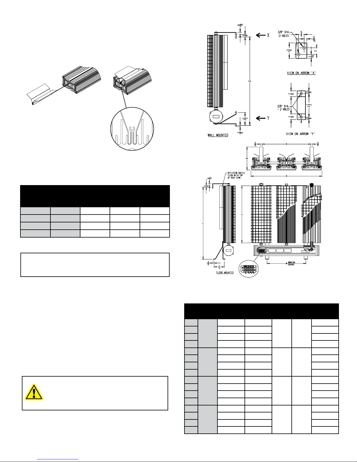
4.0 INSTALLATION - REFLECTOR BAFFLES
4.1 REFLECTOR BAFFLES (T2D units only).
Refer to Figure 1 when installing reector
bafes.
FIGURE 1 - REFLECTOR BAFFLES INSTALLATION
TABLE 1 - REFLECTOR BAFFLE PAIRS PER HEAT SINK
Heat Sink Extrusion
Length # of Pairs Size
in mm in mm
5.1 130 0 - -
11.8 300 1 8 203
18.5 470 2 8 203
25.2 640 1 24 610
NOTE: Bafes are only required for units with a T2D
temperature code rating.
4.2 Position heater front face down on a at
surface.
4.3 With the fold in the bafe positioned between
the keyhole n and the adjacent short n, slide
reector bafes onto the back of heat sink.
4.4 Ensure reector bafes are secure in place
and ush with the top of the heat sink. If
reector bafes move freely, open the fold
with a screw driver to improve the friction and
reinstall bafes.
CAUTION
THE HEATERS SURFACE IS HOT WHEN
THE HEATER IS ENERGIZED. KEEP ALL
COMBUSTIBLES AWAY FROM THE HEATER
AND MAINTAIN THE RECOMMENDED
INSTALLATIONCLEARANCESATALLTIMES.
FIGURE 2 - DIMENSIONS & MOUNTING DETAILS
TABLE 2 - HEATER DIMENSIONS
Unit B F G M N L
in (mm) in (mm) in (mm) in (mm) in (mm) in (mm)
XB1
7.250
(184)
10.250 (260) 9.625 (244)
- -
5.125 (130)
XB1 17.000 (432) 16.375 (416) 11.875 (300)
XB1 23.625 (600) 23.000 (584) 18.500 (471)
XB1 30.375 (772) 29.750 (756) 25.250 (640)
XB2
16.125
(410)
10.250 (260) 9.625 (244)
7.125
(181)
8.250
(210)
5.125 (130)
XB2 17.000 (432) 16.375 (416) 11.875 (300)
XB2 23.625 (600) 23.000 (584) 18.500 (471)
XB2 30.375 (772) 29.750 (756) 15.250 (640)
XB3
25.000
(635)
10.250 (260) 9.625 (244)
13.750
(349)
17.125
(435)
5.125 (130)
XB3 17.000 (432) 16.375 (416) 11.875 (300)
XB3 23.625 (600) 23.000 (584) 18.500 (471)
XB3 30.375 (772) 29.750 (756) 15.250 (640)
XB4
33.875
(860)
10.250 (260) 9.625 (244)
22.625
(575)
26.000
(664)
5.125 (130)
XB4 17.000 (432) 16.375 (416) 11.875 (300)
XB4 23.625 (600) 23.000 (584) 18.500 (471)
XB4 30.375 (772) 29.750 (756) 15.250 (640)

3
5.0 WALL MOUNTING
5.1 Install heater with the supplied hardware in
accordance with the Figures and instructions
below.
Step 1: Secure wall and stabilizing brackets to
mounting surface (Figure 3).
FIGURE 3 - INSTALL MOUNTING BRACKET
Step 2: Position heater face down on oor
with terminal box towards mounting brackets.
(Ensure that bafes are installed [see section
3.6 of this manual]). Angle heater such that the
terminal box rests on bottom of wall bracket.
Lift top of heater and align with top stabilizing
brackets.
Secure with supplied 1/4”-20 hex bolts and
lock washers (Figure 4).
FIGURE 4 - WALL MOUNTING DIAGRAM
Step 3: Secure bottom of heater to wall
mounting brackets with supplied 1/4”-20 hex
bolts and lock washers (Figure 5).
FIGURE 5 - ATTACH HEATER TO MOUNTING BRACKETS
6.0 FLOOR MOUNTING
Step 1: Position heater face down on the oor
with terminal box towards the wall (Figure 6).
FIGURE 6 - FLOOR MOUNTING DIAGRAM
Step 2: Fasten top stabilizing bracket(s) and
oor mounting bracket(s) to the unit. Floor
mounting brackets may be mounted in one of
three orientations (Figure 7).
FIGURE 7 - INSTALL MOUNTING BRACKET TO HEATER
Step 3: Lift top of unit and position heater
vertically against the wall. Secure stabilizing
and oor mounting brackets to the mounting
surfaces (Figure 8).
FIGURE 8 - ATTACH HEATER TO FLOOR AND WALL
CAUTION
NEVER INSTALL ONE HEATER ABOVE
THE OTHER.
TO ENSURE SAFE OPERATION, HEATER
MUSTBEINSTALLED,ASSHOWNINFIGURES
5 & 8. INSTALLATION WITH FINS IN THE
INCORRECTORIENTATIONMAYRESULTINAN
UNSAFE CONDITION (REFER TO TABLE 1).
4
WARNING
IMPROPER ORIENTATION OF THE HEATER
COULD AFFECT THE SAFE AND RELIABLE
OPERATION OF THE HEATER.
7.0 THERMOSTAT INSTALLATION
7.1 FACTORY INSTALLED - For shipping
purposes the thermostat well (located at back
of unit) has not been installed.
Position thermostat bulb perpendicular to
housing being careful not to kink the capillary.
Slide well over bulb and screw into place. Make
sure that a minimum 5 threads engagement is
achieved.
7.2 FIELD INSTALLED KIT - Most NorsemanTM
XB units are suitable for eld installation of a
thermostat kit with the operator shaft hole on the
front side of the unit and plugged with a socket
head cap screw. If a thermostat is to be eld
installed, check to verify that you have been
supplied with the correct thermostat kit. Single
phase heaters use a single pole thermostat
as supplied in kit number XTKW04481. Three
phase heaters use a double pole thermostat
as supplied in kit number XTKW04483. Follow
the instructions supplied with the kit.
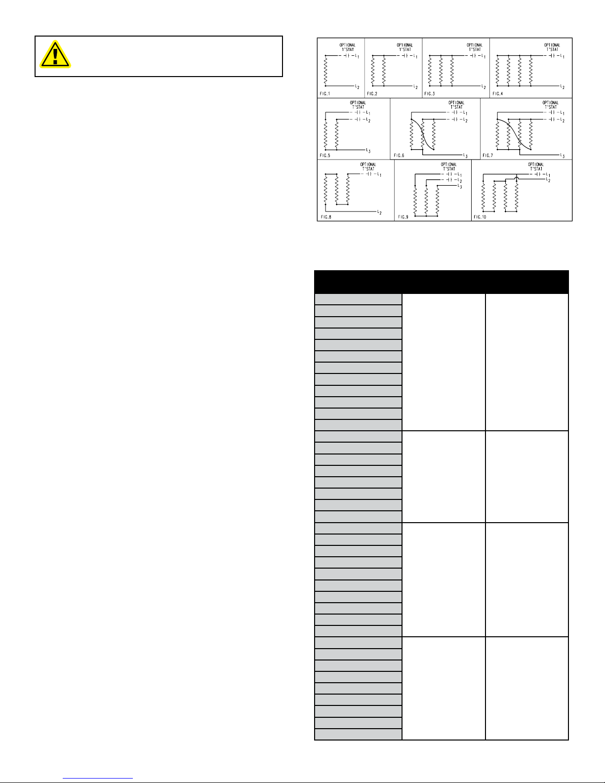
8.0 WIRING
8.1 Whenever hazardous materials are present,
ensure that the terminal housing covers are
secure before powering the heater.
8.2 Use supply wires suitable for 221°F (105°C).
8.3 Use approved conduit and conduit seals as
required by the code for hazardous locations.
8.4 To provide maximum protection each
NorsemanTM XB heater should be fused
individually using the nearest standard fuse
size which is not less than 120% of the
expected line current.
8.5 All heaters come factory prewired and ready
for direct connection to the power supply
leads.
(a) Connect the power leads to terminals
marked L1 and L2 for single phase and L1,
L2 & L3 for three phase heaters as shown in
Figure 9.
(b) Connect the ground wire to the ground
connection located in the heater terminal
housing.
FIGURE 9 - WIRING DIAGRAM
TABLE 3 - REPLACEMENT THERMOSTATS
Part No. Wiring Diagram (Figure 9)
1Ø 3Ø
XB1-1005T6
Fig. 1 -
XB1-1010T4A
XB1-1017T4A
XB1-1030T3B
XB1-1047T2D
XB1-3047T3B
XB1-3075T2D
XB1-4100T2D
XB1-6020T6
XB1-6045T4A
XB1-6125T2D
XB1-6135T2D
XB2-1075T2D
Fig. 2 Fig. 5
XB2-3150T2D
XB2-4100T3B
XB2-4200T2D
XB2-6040T6
XB2-6085T4A
XB2-6150T3B
XB2-6250T2D
XB3-1100T2D
Fig. 3
(Except
XB3-4150T3B 600V
& XB3-6125T4A 600V
use Fig. 8)
Fig. 6
(Except
XB3-4150T3B 600V
& XB3-6125T4A
600V use Fig. 9)
XB3-1125T2D
XB3-3100T3B
XB3-3200T2D
XB3-4150T3B
XB3-4300T2D
XB3-6060T6
XB3-6125T4A
XB3-6225T3B
XB3-6375T2D
XB4-1150T2D
Fig. 4 (Except XB4-
6160T4A 600V &
XB3-3250T2D 600V
use Fig. 10)
Fig. 7
XB4-3250T2D
XB4-4225T3B
XB4-4375T2D
XB4-6080T6
XB4-6160T4A
XB4-6300T3B
XB4-6450T2D
XB4-6500T2D

5
WARNING
WHENEVER HAZARDOUS MATERIALS ARE
PRESENT, ENSURE THAT THE TERMINAL
HOUSING COVERS, PLUGS, ETC., ARE
SECURED (BUT NOT OVER-TIGHTENED)
BEFORE ENERGIZING THE HEATER.
CAUTION
ALL CIRCUITS MUST BE IN THE OPEN
POSITION BEFORE REMOVING JUNCTION
OR TERMINAL BOX COVERS.
CAUTION
USE SUPPLY WIRES SUITABLE FOR 221°F
(105°C). SUPPLY WIRES ARE TO BE FUSED
WITHAPPROPRIATELYSIZED HRC FUSING.
WARNING
USE APPROVED CONDUIT AND CONDUIT
SEALS AS REQUIRED BY HAZARDOUS
LOCATION STANDARDS.
CAUTION
ENSURE THAT NO POWER IS CONNECTED
TO THE EQUIPMENT PRIOR TO MAKING
ANY CONNECTIONS.
9.0 START-UP
9.1 For heaters with a tamper-proof thermostat,
to set temperature, disconnect the power and
remove the socket head cap screw. Set the
thermostat to the desired room temperature
with a screw driver and replace cap screw.
9.2 For heaters with an externally adjustable
thermostat, set thermostat to desired
temperature by adjusting the dial.
NOTE: The thermostat temperature range is 0° -
100°F (-18° - 40°C) with an operating differential of
5 - 7°F (3 - 4°C).
9.3 Install the terminal box cover and tighten
securely.
9.4 Check to ensure that all plugs, screws, and
covers are securely in place.
9.5 Check associated electrical equipment.
9.6 Check that all wall/oor mounting bracket
connections are tight.
9.7 Turn on the supply power.
WARNING
TO PREVENT UNSAFE OPERATION OF THE
HEATER DO NOT EXCEED THE MAXIMUM
ALLOWABLE AMBIENT OPERATING
TEMPERATURE OF 104°F (40°C).
10.0 MAINTENANCE
10.1 Periodically inspect the heater installation to
ensure that all connections, ttings, plugs,
screws, covers, etc. are tight and free of
corrosion.
10.2 Check that the reector bafes (if required)
have not moved upwards or downwards in
relation to the heat sink.
10.3 Check the extrusions of the heater for dust
and debris. A blast of compressed air is
recommended for cleaning the heat sink. If air
is not available, disconnect the power supply
to the heater and when cool, wipe it down
with a damp cloth or soft brush. Remove wire
guards prior to cleaning.
WARNING
DISCONNECT POWER FROM THE
HEATER BEFORE PERFORMING ANY
MAINTENANCE. FAILURE TO DO SO CAN
RESULT IN PROPERTY DAMAGE, INJURY
OR DEATH.
CAUTION
DO NOT USE WATER TO CLEAN HEATER.
10.4 The heat sink is anodized or painted black
to ensure that the maximum area code
temperature is not exceeded. After an
extended period of use or in extremely harsh
environments the anodization/paint may wear
away leaving bare surfaces. For continued
safe operation, these surfaces must be
repainted. When repainting use only black
high temperature resistant paint.
10.5 Except for thermostat replacement, eld repair
of the heater shall not be normally undertaken.
In the event that the heater must be repaired,
contact the factory for a return authorization
number.
11.0 SPARE PARTS
TABLE 4 - REPLACEMENT THERMOSTATS
Voltage Thermostat Part No.
One Phase Heaters XTKW04481
Three Phase Heaters XTKW04483

6
NOTES

7
NOTES

PLEASE ADHERE TO INSTRUCTIONS PUBLISHED IN THIS MANUAL.
Failure to do so may be dangerous and may void certain provisions of your warranty.
For further assistance, please call:
WARRANTY: Under normal use the Company
warrants to the purchaser that defects in material or
workmanship will be repaired or replaced
without charge for a period of 18 months from
date of shipment, or 12 months from the start date of
operation, whichever expires rst. Any claim for
warranty must be reported to the sales ofce where the
product was purchased for authorized repair or
replacement within the terms of this warranty.
Subject to State or Provincial law to the contrary, the
Company will not be responsible for any expense for
installation, removal from service, transportation, or
damages of any type whatsoever, including damages
arising from lack of use, business interruptions, or
incidental or consequential damages.
The Company cannot anticipate or control the
conditions of product usage and therefore
accepts no responsibility for the safe application and
suitability of its products when used alone or in
combination with other products. Tests for the safe
application and suitability of the products are the sole
responsibility of the user.
This warranty will be void if, in the judgment of the
Company, the damage, failure or defect is the result of:
• vibration, radiation, erosion, corrosion, process
contamination, abnormal process conditions,
temperature and pressures, unusual surges or
pulsation, fouling, ordinary wear and tear, lack of
maintenance, incorrectly applied utilities such as
voltage, air, gas, water, and others or any
combination of the aforementioned causes not
specically allowed for in the design conditions or
• any act or omission by the Purchaser, its agents,
servants or independent contractors which for
greater certainty, but not so as to limit the generality
of the foregoing, includes physical, chemical or
mechanical abuse, accident, improper
installation of the product, improper storage and
handling of the product, improper application or the
misalignment of parts.
No warranty applies to paint nishes except for
manufacturing defects apparent within 30 days from
the date of installation.
The Company neither assumes nor
authorizes any person to assume for it any other
obligation or liability in connection with the product(s).
The Purchaser agrees that all warranty work required
after the initial commissioning of the product will be
provided only if the Company has been paid by the
Purchaser in full accordance with the terms and
conditions of the contract.
The Purchaser agrees that the Company makes
no warranty or guarantee, express, implied or
statutory, (INCLUDING ANY WARRANTY OF
MERCHANTABILITY OR WARRANTY OF FITNESS
FOR A PARTICULAR PURPOSE) written or oral, of
the Article or incidental labour, except as is expressed
or contained in the agreement herein.
LIABILITY: Technical data contained in the catalog or
on the website is subject to change without notice. The
Company reserves the right to make dimensional and
other design changes as required. The Purchaser
acknowledges the Company shall not be obligated
to modify those articles manufactured before the
formulation of the changes in design or improvements
of the products by the Company.
The Company shall not be liable to compensate or
indemnify the Purchaser, end user or any other party
against any actions, claims, liabilities, injury, loss, loss
of use, loss of business, damages, indirect or conse-
quential damages, demands, penalties, nes, expens-
es (including legal expenses), costs, obligations and
causes of action of any kind arising wholly or partly
from negligence or omission of the user or the mis-
use, incorrect application, unsafe application, incor-
rect storage and handling, incorrect installation, lack
of maintenance, improper maintenance or improper
operation of products furnished by the Company.
Edmonton
Head Ofce
1-800-661-8529
(780) 466-3178
F 780-468-5904
Oakville
1-800-410-3131
(905) 829-4422
F 905-829-4430
Orillia
1-877-325-3473
(705) 325-3473
F 705-325-2106
Houston
1-855-219-2101
(281) 506-2310
F 281-506-2316
Denver
(303) 979-7339
F 303-979-7350
5918 Roper Road, Edmonton, Alberta, Canada T6B 3E1
Phone: (780) 466-3178 Fax: (780) 468-5904
24 Hr. Hotline: 1-800-661-8529
(U.S.A. and Canada)
Please have model and serial numbers available before calling.
This manual suits for next models
3
Table of contents
Other Norseman Heater manuals


